Author Topic: CVR Electric Water Pump Adapters for the FE  (Read 102182 times)

0 Members and 1 Guest are viewing this topic.

fe66comet

  • Guest
Re: CVR Electric Water Pump Adapters for the FE
« Reply #150 on: February 11, 2013, 07:20:10 PM »
I can't wait to bolt it up my engine !!!

69Cobra

  • Jr. Member
  • **
  • Posts: 40
  • A goal without a plan is just a wish
    • View Profile
Re: CVR Electric Water Pump Adapters for the FE
« Reply #151 on: February 14, 2013, 10:08:58 AM »
Very nice Jay!!! I've been wondering what I was going to do for a water pump on my Stocker motor and I think I know the answer now. The only question I have to a racing application is the 55 gpm flow to much? I'm not sure that's possible but will that give it time in the radiator to cool down before its cycled back through? I guess you could always put a restrictor at the t-housing if that was the case.

I know you're burnt out on this deal but I've got a question? In an all out racing application there has been performance increases with a reverse flow system where you are cooling the intake and heads first. Do you know what it would take to make this pump work as a reverse flow system? Electrically you would just reverse the + & - and that will spin the motor backwards but what about the impeller? Would what they have work?
Kris Rachford
69 Cobra 428 CJ Jerico 4 speed
NHRA C/Stock Eliminator 3032

jayb

  • Administrator
  • Hero Member
  • *****
  • Posts: 7418
    • View Profile
    • FE Power
Re: CVR Electric Water Pump Adapters for the FE
« Reply #152 on: February 14, 2013, 12:00:08 PM »
My take on that is that you can never have too much flow from the water pump.  The thermostat will function to restrict water flow to the radiator, but I'm not sure that enters into the equation.  Not to open up a somewhat famous argument about cooling  ;D, but I'm not one of those folks who believes that you need to slow down the water in the radiator to make it cool.  No matter how fast the water is going in the radiator, the same amount of water is contained in the radiator at all times, and the same amount of cooling per unit time is taking place.  While it is true that if a particular "parcel" of water goes through the radiator faster, it will receive less cooling, it is also true that the same parcel of water will go through the engine faster, and therefore receive less heating.  Thermodynamically, it all evens out.  Another way to think of this is that if you slow down the water in the radiator, as it exits it will be cooler, but then it will travel through the engine slower, so as it comes out of the engine it will be hotter.  Thinking of it in that way, the faster you can circulate water in the cooling system, the more stable the cooling system temperature will be.  If I could bolt a 100 gpm pump onto any of my engines, I'd do it.

Going reverse through the cooling system, on the other hand, makes a lot of sense from a horsepower perspective, because the water will be at its coolest coming out of the radiator, and the cylinder heads are where most of the heat is.  So, cooler water will absorb more heat from the heads than water that has already been heated somewhat by traveling through the block.  The horsepower gain is thermodynamic; keeping the combustion chamber and intake charge cooler by reducing the cylinder head temperature results in more heat extracted from the combustion process.  However, I don't know if you can just reverse the polarity of the electric pump motor to effect this change; I haven't taken my CVR pump apart to see if the impeller is directional.  I strongly suspect that it is, in which case a different impeller would be required in addition to the polarity change on the motor.

Maybe I'll take my CVR pump apart and look this weekend...
Jay Brown
- 1969 Mach 1, Drag Week 2005 Winner NA/BB, 511" FE (10.60s @ 129); Drag Week 2007 Runner-Up PA/BB, 490" Supercharged FE (9.35 @ 151)
- 1964 Ford Galaxie, Drag Week 2009 Winner Modified NA (9.50s @ 143), 585" SOHC
- 1969 Shelby Clone, Drag Week 2015 Winner Modified NA (Average 8.98 @ 149), 585" SOHC


afret

  • Guest
Re: CVR Electric Water Pump Adapters for the FE
« Reply #153 on: February 14, 2013, 12:08:37 PM »
On the stocker motor we just run a CSR 35 GPM pump with no thermostat and it works great.  The engine had the Moroso setup before the CSR and that one work fine too.  Took the CSR off the street motor though to use the 55 GPM pump with Jay's adapters to make sure the engine will get enough water flow for a drive on the highway.

Might as well use a 55 GPM pump though if you need to get a pump anyway.

69Cobra

  • Jr. Member
  • **
  • Posts: 40
  • A goal without a plan is just a wish
    • View Profile
Re: CVR Electric Water Pump Adapters for the FE
« Reply #154 on: February 14, 2013, 12:18:30 PM »
Jay,
 I guess I didn't think about the water staying in the engine long, thanks for the explanation there. Also, with the reverse flow and being able to cool the intake charge and combustion chambers better you should be able to run more timing and burn more fuel without the risk of detonation, yes?

afret,
 I've been looking at the aftermarket pumps but none of them allowed me to bolt up the alternator brackets until now thanks to Jay. How did you bolt up your alternator with the CSR pump?
« Last Edit: February 14, 2013, 12:32:00 PM by 69Cobra »
Kris Rachford
69 Cobra 428 CJ Jerico 4 speed
NHRA C/Stock Eliminator 3032

jayb

  • Administrator
  • Hero Member
  • *****
  • Posts: 7418
    • View Profile
    • FE Power
Re: CVR Electric Water Pump Adapters for the FE
« Reply #155 on: February 14, 2013, 12:59:24 PM »
Jay,
 I guess I didn't think about the water staying in the engine long, thanks for the explanation there. Also, with the reverse flow and being able to cool the intake charge and combustion chambers better you should be able to run more timing and burn more fuel without the risk of detonation, yes?


Correct about reducing the risk of detonation, so more timing should be OK.  Thinking about this idea a little more, I see a few potential issues.  The thermostat is unidirectional; it would have to be reversed.  It also might not work at all, since the temperature sensitive portion of the thermostat would be facing the radiator now, instead of the engine, and the radiator is not the source of the heat.  Maybe removing the thermostat would be best in that arrangement.  Also I wonder if reversing the direction of flow would make the water pump less efficient?  Something to think about...
Jay Brown
- 1969 Mach 1, Drag Week 2005 Winner NA/BB, 511" FE (10.60s @ 129); Drag Week 2007 Runner-Up PA/BB, 490" Supercharged FE (9.35 @ 151)
- 1964 Ford Galaxie, Drag Week 2009 Winner Modified NA (9.50s @ 143), 585" SOHC
- 1969 Shelby Clone, Drag Week 2015 Winner Modified NA (Average 8.98 @ 149), 585" SOHC


fe66comet

  • Guest
Re: CVR Electric Water Pump Adapters for the FE
« Reply #156 on: February 14, 2013, 01:06:22 PM »
I would think a setup for a serpentine drive engine would be available as rotation is reversed.

afret

  • Guest
Re: CVR Electric Water Pump Adapters for the FE
« Reply #157 on: February 14, 2013, 02:58:42 PM »

afret,
 I've been looking at the aftermarket pumps but none of them allowed me to bolt up the alternator brackets until now thanks to Jay. How did you bolt up your alternator with the CSR pump?

We got the CSR pump on 3 FE's and just use long studs on the bottom passengers side water pump bolt hole and the 3/8" timing pointer bolt  hole to hold the brackets for mounting the alternator low.  The brackets are different on each engine but we use the same bolt holes with aluminum spacers.


For the street car, I modified a low mount bracket from a place called CRAP that one of the members of the other FE Forum runs.  The two holes on the right are for the mounting studs that you can see in the other photo:


« Last Edit: February 14, 2013, 07:48:57 PM by afret »

fe66comet

  • Guest
Re: CVR Electric Water Pump Adapters for the FE
« Reply #158 on: February 14, 2013, 03:12:50 PM »
When I started to do some drawings of my accessory drive I was going to mount my alternate low along with my  PS pump for my rack. Also I am going serpentine but if I use Jays mounts it cuts a lot of fan work out of the equation. I like easier and hate welding and grinding.

ScotiaFE

  • Hero Member
  • *****
  • Posts: 1409
  • Howie
    • View Profile
Re: CVR Electric Water Pump Adapters for the FE
« Reply #159 on: February 14, 2013, 06:14:29 PM »
That is always a debate. LOL
Although over the years I have always found that a 195 T stat would keep an engine cooler than a 180 t stat.
Of course a bigger rad always helps the equation.  ::)
Not mention excellent air flow control and fan ducting.
Your new water pump gizzmo is very temping. It is just money after all. :D

fe66comet

  • Guest
Re: CVR Electric Water Pump Adapters for the FE
« Reply #160 on: February 14, 2013, 06:30:36 PM »
The HP gain is nice but also traffic can destroy an engine here, even stock aluminum ones can die an early death as they crawl along screaming for mercy on a 105 degree day. And of course the driver is not going to turn the a/c off at any cost LOL. But the a/c stops when the engine goes up in a puff of steam and blows a head or block. Then they ask the mechanic why did this happen as it was a major inconvenience ( ready to blame him).

69Cobra

  • Jr. Member
  • **
  • Posts: 40
  • A goal without a plan is just a wish
    • View Profile
Re: CVR Electric Water Pump Adapters for the FE
« Reply #161 on: February 16, 2013, 02:29:08 AM »

afret,
 I've been looking at the aftermarket pumps but none of them allowed me to bolt up the alternator brackets until now thanks to Jay. How did you bolt up your alternator with the CSR pump?

We got the CSR pump on 3 FE's and just use long studs on the bottom passengers side water pump bolt hole and the 3/8" timing pointer bolt  hole to hold the brackets for mounting the alternator low.  The brackets are different on each engine but we use the same bolt holes with aluminum spacers.


For the street car, I modified a low mount bracket from a place called CRAP that one of the members of the other FE Forum runs.  The two holes on the right are for the mounting studs that you can see in the other photo:


Interesting... I wouldn't have thought that the timing pointer hole in the timing cover wouldn't dealt with that stress.

Thanks for sharing.
Kris Rachford
69 Cobra 428 CJ Jerico 4 speed
NHRA C/Stock Eliminator 3032

afret

  • Guest
Re: CVR Electric Water Pump Adapters for the FE
« Reply #162 on: February 16, 2013, 11:40:40 AM »

Quote
Interesting... I wouldn't have thought that the timing pointer hole in the timing cover wouldn't dealt with that stress.

That hole goes through to the block and holds a 3/8" stud.  It doesn't just screw into the aluminum timing cover.

69Cobra

  • Jr. Member
  • **
  • Posts: 40
  • A goal without a plan is just a wish
    • View Profile
Re: CVR Electric Water Pump Adapters for the FE
« Reply #163 on: February 16, 2013, 12:06:17 PM »
Gotcha.... I misunderstood. lol
Kris Rachford
69 Cobra 428 CJ Jerico 4 speed
NHRA C/Stock Eliminator 3032

jayb

  • Administrator
  • Hero Member
  • *****
  • Posts: 7418
    • View Profile
    • FE Power
Re: CVR Electric Water Pump Adapters for the FE
« Reply #164 on: February 17, 2013, 10:01:11 PM »
Ever have one of those weeks where nearly everything goes wrong when you are trying to get something done?  That was the story of my week this week, but persistence finally paid off on Sunday night, and I'm claiming victory on these water pump adapters.  All the machining parameters are finished, the adapters bolt onto the CVR pump and the FE and there are no leaks, and I have dyno data showing a horsepower increase over a mechanical pump. 

So last Monday I made a list of what I needed to get my 428CJ back on the dyno.  The major thing was engine mounts; I only have two sets of Mustang mounts, and they are both now being used in my Mach 1 and my Shelby clone.  So I went on the website at Mustangs Unlimited on Monday night and ordered the plates that bolt to the engine, and also the mounts.  Since I had the machining operations in the can for the adapters, I also ordered more aluminum from the local metal supply place, to be ready for pickup on Friday this week.  I figured I could feed the CNC machine all weekend and get a bunch of these things cranked out; I had a few feet of stock left, but didn't figure that would last me too long.

After taking care of some family stuff the first part of the week, on Thursday night when I came home from work I was looking forward to getting started on this.  When I got home there was the Mustangs Unlimited box, so I opened it up to look at the mounts, and what do you know - the plates that bolted onto the block were back ordered.  I wish their web site would give you some clue about that, but its not very advanced in that respect.  OK, I figured I could get around that issue.  Out the shop by 7:00, and started slicing up the remaining 3" X 4" aluminum bar in my bandsaw, so I could start machining some.  Halfway through the first cut, the bandsaw blade broke.  Turned out it was my last 10 tooth per inch blade, and the only other one I had was 14 teeth per inch.  That was going to saw really, really slow.  No problem, though, Menards carries those blades, so I figured I'd pick one up at lunch on Friday.  Took the whole rest of the evening for the 14 tooth blade to finish the first cut.  So much for starting on the CNC work...

Friday at lunch I whipped over to Menards to pick up the bandsaw blade.  They were nowhere to be found; just a bunch of wood cutting blades were in stock.  The Menards guy said they discontinued carrying those blades.  Those rotten no good so and so's!  I was mad when I walked out of there.  Drove up to the metal supply place to pick up my aluminum, and sure enough, it wasn't ready.  The "pick ticket" got lost apparently, and nobody cut the aluminum that I needed.  No way I could hang around and wait, I had to get back to work.  Oh well, I wouldn't have been able to cut it anyway with that 14 tooth bandsaw blade.  The guys at the metal place promised it would be ready on Monday.

When I got home Friday night after work I ordered the bandsaw blades I needed from Enco; they should be here this coming Tuesday or Wednesday.  The only thing I could do was cut up the pieces that I had left (SLOWLY), and machine those.  I got going on that Friday night, and continued this work into Saturday.  I had a few more parts made up as I began to get my 428CJ ready for the dyno Saturday afternoon.  First I got it bolted onto the dyno stand, and after a quick inspection I realized that this was going to be a bigger job than I thought.  Last time I ran this engine it was to run some of the final tests for my book, and I had installed solid lifters on the Performer RPM hydraulic cam to do the solid vs hydraulic comparison in the book, and I had also installed an oil line that ran from the valley of the engine out through the opening between the intake and head, and out of a hole in the valve cover, so I could monitor the oil presure at the back of the engine during the dyno pull (this data is also in my book).  If I wanted to pull that oil line and replace the solid lifters with the hydraulics that were supposed to go in there, I'd have to pull the engine apart.  I didn't really want to spend the time doing that, but I didn't feel I had much of a choice; I kind of figured I was running on borrowed time with those solid lifters, and wanted to get the hydraulics back in there, at least until I changed to a real solid cam.  So, reluctantly I tore into the engine. 

At some point late Saturday afternoon, when I was working on the engine, I looked at the water jacket openings where the CVR adapters were supposed to fit.  As mentioned previously in the thread, the left (drivers) side water pump opening has a point to it, making it bigger than the opening on the right side of the engine.  I had measured this when I designed the O-ring groove forthe adapters, but looking at it again now it sure seemed big.  I had just painted  the front of the engine to make it look a little better, so I decided to bolt on one of the adapters with the O-ring installed, figuring that the O-ring would leave an impression in the tacky paint, and I could be sure that the O-ring was big enough to seal.  So I did that.  Here's a picture of the left side water pump opening after the adapter was removed:


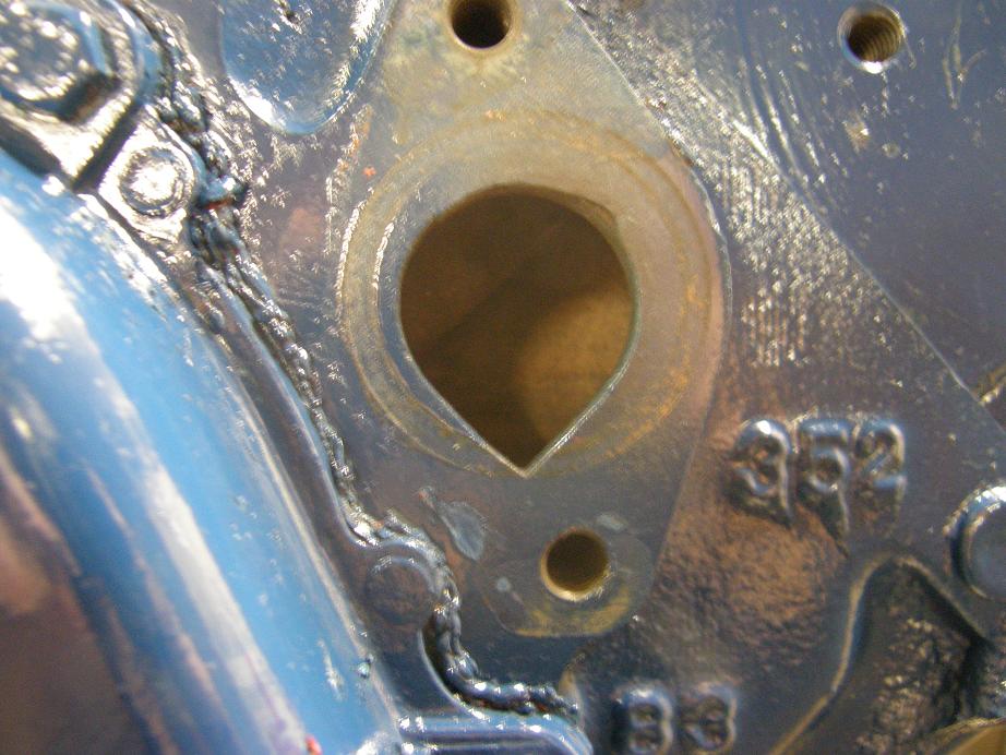
Well, crap.  Didn't look to me like that was going to seal!  I must have measured wrong or something; I should have test fit it before.  What was worse was that I had already built about three of these things on Saturday, and none of them were going to work.  Looked like I wasn't done with the CNC programming after all; back to the drawing board.  I stopped work on the engine and spent Saturday night on the CAD and CNC programming software, coming up with a different shape for the O-ring to fit into.  I got some of it machined on Saturday night, but I was up until 1:30 AM doing it.  This morning I was back out in the shop by 8:30, and finished the CNC programs, and let the machine run while I got back to work on the engine.  I decided that rather than re-install the Blue Thunder intake that the engine had before, I'd put a Performer RPM on it.  I was thinking ahead to the FE intake adapters; if I got some good data on the  Performer RPM, then I could compare it to the intake adapter fitted with the 351C Performer RPM intake, which I thought would be interesting.  Also, I have a 282S Comp Cams solid cam that I want to put in this engine rather than the Performer RPM hydraulic cam that is in there now.  I thought about changing to that cam this morning while the CNC machine was whirring away, but I decided that I would wait until the intake adapters were done.  Then, I could change the cam with the intake adapter in place, and see how that worked out.  So I ended up re-installing the hydraulic lifters and put the Performer RPM intake on there. 

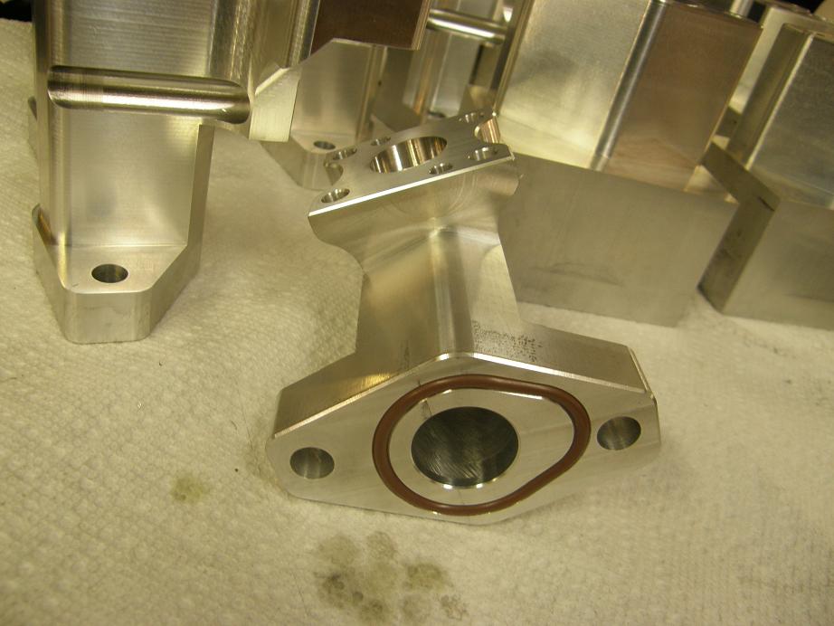
I was done with this about noon, and the CNC machine had finished up the revised left side water pump adapter.  I installed the O-ring and it looked pretty good; here is a photo:


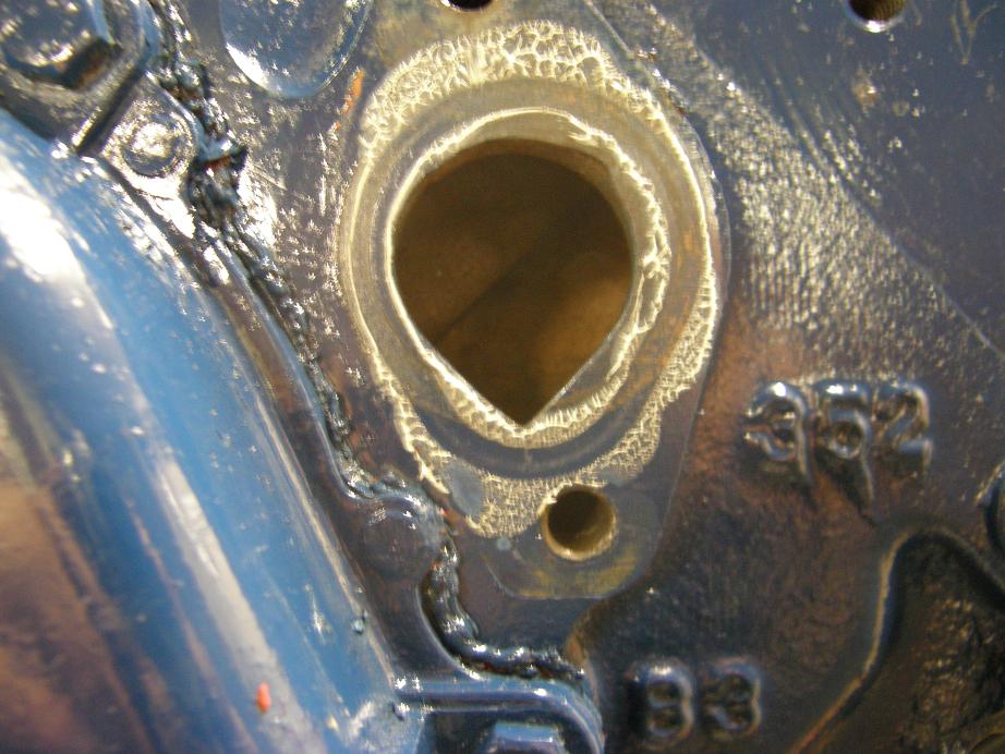
Just to be sure, I put a coat of grease on the O-ring, and installed the adapter on the block.  After removing it, I got a completely satisfactory witness mark:


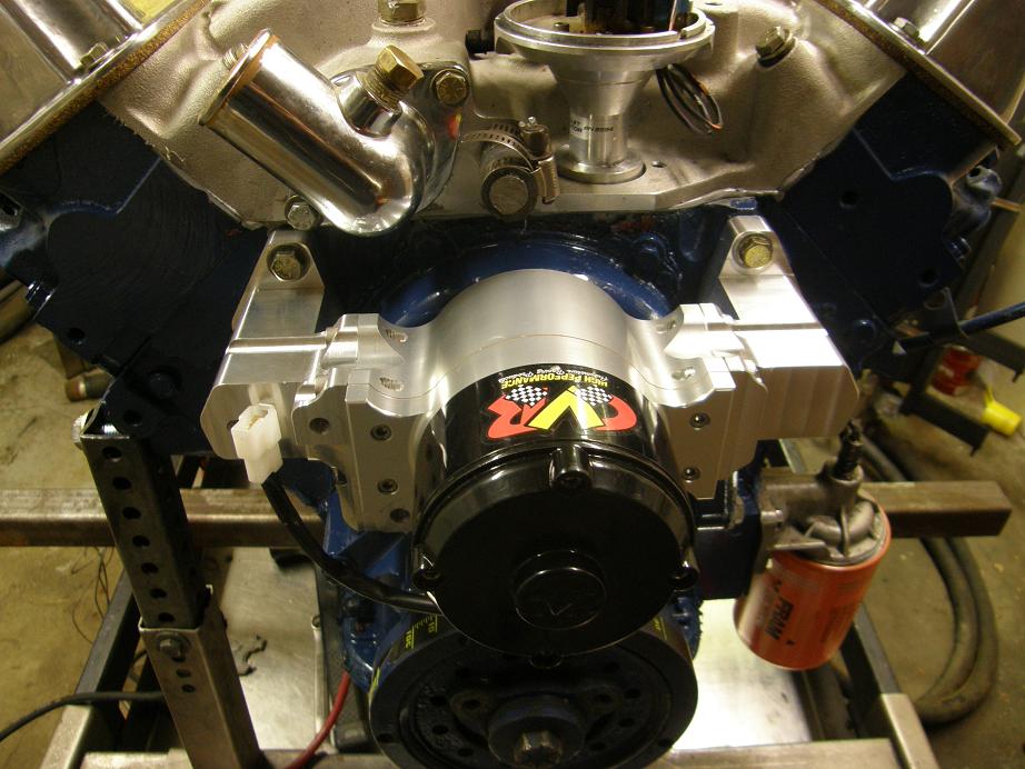
That looked pretty good to me, so I bolted the water pump together and put it on the engine.  Definitely has a little more bling than a stock pump:


I spent the rest of the afternoon getting the engine ready to run on the dyno, with a two hour break in the middle to take my daughter out driving.  (She is 15 and has her permit now, and has been driving a little in my wife's Subaru.  She wanted to drive my truck, so I took her to an empty parking lot where she could practice with it a little, then we went out on the road for an hour or so.  She has a hard time staying between the lines, and she tends to drive on the shoulder because she is scared of the oncoming traffic.  As a result she almost took out a mail box, and I had a few white knuckled moments during the ride, but overall she did pretty well.  Sheesh, this is probably going to be a regular thing for a while LOL!)

By 6:30 tonight the engine was ready to run.  First thing I did was fill it with water, and given the problems of this week I fully expected leaks.  Thankfully, the engine was bone dry; no leaks at all.  That was a relief; looked like my water pump adapters were going to work.  Then I turned on the CVR pump, and was really impressed with how much water it was putting out, based on the sounds coming from the dyno's cooling tower.  Sounded like a garden hose going in there.  Finally I started the engine and warmed it up, and made a couple of dyno pulls.  I have data from this exact combination when I did the dyno testing for my book, so I was anxious to see how it compared to the original data, which was taken with the Edelbrock mechanical pump installed on the engine.  I plotted the comparison data in Excel, and up to about 3800 RPM there really wasn't a difference.  But after that, it was a different story.  Here's the data:


There's about 10 horsepower, right where you want it if you are going down the track.  Color me sold on electric water pumps  :D

I felt the need for a gratuitous dyno video, so here it is.  It's too bad you can't see the computer screen in the video; it is all whited out and I've never been able to get it visible during these dyno pulls, but the sound is great.  This is only a 425HP engine (now 435 with the electric pump), and the pull only goes to 5500 RPM, but in the dead of winter in Minnesota it is still worth hearing.  Sounds a lot better than all the snowmobiles...

http://youtu.be/8RO-yS8p08M


« Last Edit: February 17, 2013, 10:33:15 PM by jayb »
Jay Brown
- 1969 Mach 1, Drag Week 2005 Winner NA/BB, 511" FE (10.60s @ 129); Drag Week 2007 Runner-Up PA/BB, 490" Supercharged FE (9.35 @ 151)
- 1964 Ford Galaxie, Drag Week 2009 Winner Modified NA (9.50s @ 143), 585" SOHC
- 1969 Shelby Clone, Drag Week 2015 Winner Modified NA (Average 8.98 @ 149), 585" SOHC