I installed the steering shaft only on the car. The tube was painted a while back along with a few other pieces and for some reason, the paint doesn’t quite match the rest of the interior pieces. Body shop guys suspects the paint went bad from sitting. It was several years between parts. Anyway……I was surprised that it was relatively easy to get to the rag joint to tighten the bolts. You may notice in steering wheel moving around as I turn it in the video.
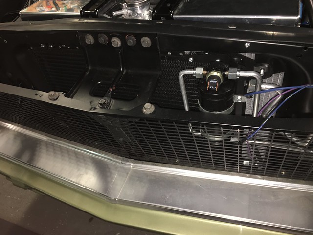
My wife assembled the condenser, mounting brackets, dryer, and hoses to get it back into the engine compartment. She got it bolted into the car and I checked to fittings to make sure they were tight. I bought a 4 core Champion radiator, factory fan shroud, an 18” replacement type fan blade from Summit, and the Hayden 2711 fan clutch to hopefully keep the car cool. It’s a HUGE radiator. The shorter fan clutch is a “have to”. There is just enough room the pull the fan clutch off the water pump with a piece of cardboard between it and the radiator. It’s been 25 years or so since I pulled the motor. I have forgotten how much of a puzzle this thing is to put together. Plenty of parts on and off as I figured it out on Saturday. The last time out for install, the PS pump & AC compressor came off, fan shroud set over water pump, fan & clutch on, radiator goes in like a diamond then rotates into position and everything else gets bolted back on.
 IMG_6985
 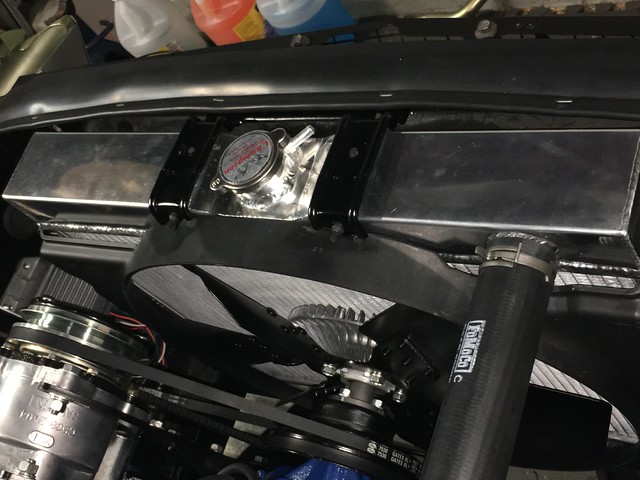 IMG_6986
I taped up the rest of the wires under the dash that I didn’t need to start, mostly lighting stuff. Connected the gauge cluster pig tail and installed the starter switch. I watched about 3-4 videos trying to figure out how to get the tumbler installed. Connected the battery and I saw one little spark as I connected it. Pull back and look around, then reconnect, no spark this time. I saw the door lights come on. Never seen that before, WOW. Look around the car and watch for smoke or burning wire. Nothing. Turn the key to the right and keep watching….the oil and alternator lights came on. Things are looking up. Twist it a little farther and it starts cranking over. WOO HOO. Roll it out of the garage, pour gas in the tank and look for leaks. Pour water in the radiator and look for leaks. I haven’t changed anything since it came home from the dyno, so it should run if the wiring is right. Prime the carb and hit the key….it coughs and sputters and tries to start. More gas in the carb and hit the key and it comes to life, about 10:30 on Saturday night. I was smiling like a kid at Christmas. Walking around the car with a flash light looking at stuff, grinning from ear to ear, holly crap there’s a big puddle under the car and its growing. Fuel coming from around the fuel pump. Kill it and grab a wrench. Yep, the line up to the carb has a loose fitting at the pump. Cranked it up again and let it run for 15-20 minutes. It’s a happy day for me. Poke fun if you like, I was excited. This fall will be 30 years I’ve owned this car, its never ran till now.
It started, so the Duraspark wiring must be right. Not sure if the Tach will work. The oil light went out after firing up, so that must be right. The alternator light is still on, looks like I missed that one.
New list of thing to look at:
Charging system
Temperature gauge pegs while running
Gas gauge does not register
Car pops and backfire when I idle it down
Vacuum module is ruptured
Time to start tuning. We will see how much I bug you guys with questions.
Went for a short test drive on Easter Sunday.
https://youtu.be/YtcTRW0d7zI

