I bought a 3/8” fuel line for a 68 to install. It was a little tricky getting it around the subframe connectors, but it went. Had to drill a few holes also.
 IMG_1344
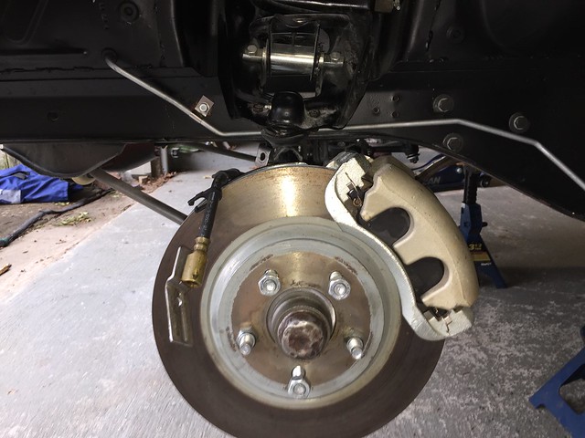
 The front brakes use MS’s GT brackets. I got take off calipers, hoses, dust shields, and pads in 13 or 14, when they were still available. Everything bolted up good. I used the late model hoses supplied with the calipers. Just like the back, I rounded off the extra connectors for holding the ABS cable. A little cutting, filling, and drilling got the bracket on the end ready for bolting to the car.
 IMG_1345
 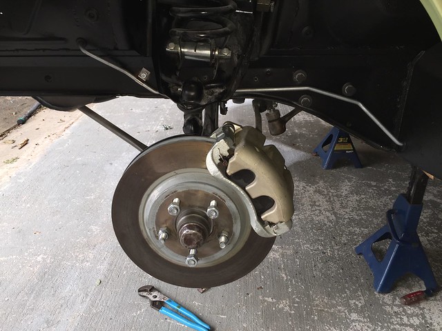 IMG_1343
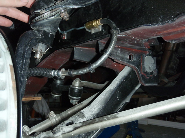
Years ago, (I’ve been buying parts since 04 as money was available) I bought the pre bent brake lines for a disk brake car, mine original had drums. The decision made since at the time cause I wanted disc!! I’m not sure if it was the mid-year change or the difference in a drum and disc car, but the line to the rear wasn’t bent to fit my car. The front lines wasn’t working out either. So, another set of brake lines were bought. Those fit much better. I think I’m fair at bending the tubing, but didn’t want the hassle for the entire car and I was dreading flaring the ends. The more factory ends the better. Had issues with that in the 90’s and haven’t done it since.
With the hard lines in place, it was time to mate them to the late model hose that need a bubble flare. From advice on the site, I bought the shortest hard line from O’reilly’s for the fittings and cut them off. The hex on those fittings are not the same size for a stick. Figured that out before the second flare!! Several you tube videos later, a borrowed tool from a guy at work, and I was set. On my very first practice piece, I broke the die stuck in the end of the line. : ( I bought a flaring kit from Harbor Freight, took a little more time, and was able to get the four ends flared that I needed. Then gave the tool to the guy at work along with his partial set. Breaking someone else’s tools is the main reason I try not to borrow stuff.
 P7160027
 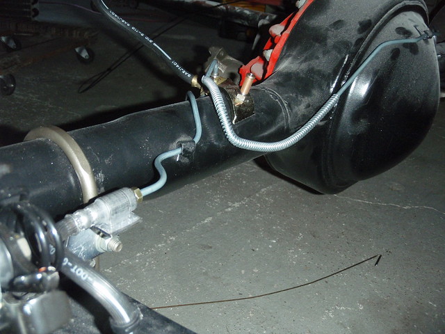 P7160031
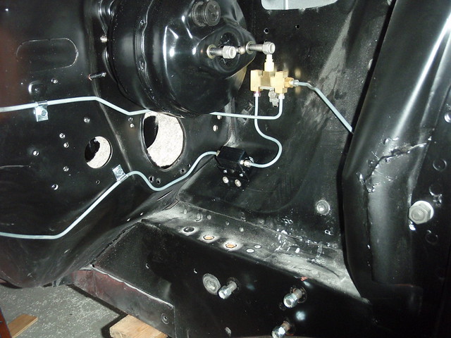
 That got my lines complete from the calipers back to the pressure differential valve. I needed to install a proportioning valve to go with the rear disc. I was hesitant to mount between the apron and the booster down low with the knob up cause it would be extremely difficult to get to for adjustment. The Borgeson box went in so I would not interfere with the Proportioning valve. The booster was in place already. After asking if it had to be mounted in some certain orientation, I drilled a hole in the apron and mounted it with the knob down into the fender well. Should be a lot easier to adjust. Made several attempts at the double flare with the flaring bar I had with no luck. More you tube videos, and I was back to Harbor Freight for another flaring kit that I would keep. A couple of test runs later and they went together. Brake lines complete from distribution block to calipers. Now, will they leak when brake fluid enters the picture?

I sure hope not.
 P7240017
 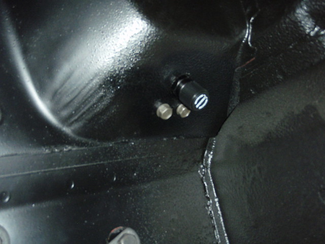 P7240019
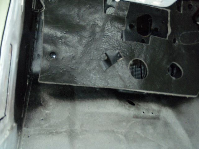
The firewall from the inside of the car was painted silver to reflect some light, and it helped to see. Added body sealer to the seams on the bottom side of the cowl for good measure. Then sprayed the rubberized under coating on the inside firewall, back too hard to see. Mounted the clutch and brake pedals in the car, then the power booster went on.
 P7220022
Back in March, I had the parts in my truck at work to take in for balancing. It was show and tell for one of the other guys at the office. He was looking at the rods and said the pin is floating. I’m like “yea, FE’s are that way, you Chevrolet boys have to pay extra for that”. Then he showed me where the random rod he picked up had the bronze bushing sliding around on the pin.

The engine will be a .060 over 410. I dug the crank out of a 410 in the early 90’s from a pick a part. Didn’t cost much at all and the afternoon to pull it out. I should have bought the complete engine, lessons learned.
The first trip over, I took the crank, rods, and cast truck pistons to Houston Engine and Balance for balancing. After discussions on pricing for new bushings in the little end and new bolts, and the cost of new rods, I opted for new Eagle rods. Next trip over was to carry the new rods, harmonic balancer, flywheel, and pressure plate. Trip after that was the block for a bath and decking. The crank was standard, got mag’d, and cleaned up at .010. The flywheel was drilled for an 11” clutch and the pressure plate was 11 ½”. Jeff drilled the flywheel to match. The block was cleaned, lifter galleries tapped, new cam bearings installed, square decked and cut for a zero deck height. All came back ready for assemble.
I ordered a set of Felony heads from Survival and those are now sitting in the garage too. I will run a hydraulic roller and will be asking for help on selection.
Next step in car assemble will be the master cylinder to complete the brake lines and installing the hydraulic clutch. Over the last couple of weekends we did some cleaning and purging on the garage. Still have some more to go. We can get 3 cars in a 3 car garage, haven't been able to do that since we bought the house.
Update photos 6/4/18


