Author Topic: 545" High Riser Build  (Read 201739 times)

0 Members and 1 Guest are viewing this topic.

ScotiaFE

  • Hero Member
  • *****
  • Posts: 1409
  • Howie
    • View Profile
Re: 545" High Riser Build
« Reply #135 on: February 20, 2012, 09:45:09 AM »
Getting close to firing Minky up. ::)


jayb

  • Administrator
  • Hero Member
  • *****
  • Posts: 7564
    • View Profile
    • FE Power
Re: 545" High Riser Build
« Reply #136 on: February 20, 2012, 11:38:51 AM »
Well, I don't know about that, Howie, but I am supposed to be getting the new pistons this week...
Jay Brown
- 1969 Mach 1, Drag Week 2005 Winner NA/BB, 511" FE (10.60s @ 129); Drag Week 2007 Runner-Up PA/BB, 490" Supercharged FE (9.35 @ 151)
- 1964 Ford Galaxie, Drag Week 2009 Winner Modified NA (9.50s @ 143), 585" SOHC
- 1969 Shelby Clone, Drag Week 2015 Winner Modified NA (Average 8.98 @ 149), 585" SOHC


ScotiaFE

  • Hero Member
  • *****
  • Posts: 1409
  • Howie
    • View Profile
Re: 545" High Riser Build
« Reply #137 on: February 21, 2012, 07:53:53 AM »
At the speed that I am building my lowly Geny your Minky will
be on a rebuild cycle by the time I get mine fired up.
I did buy a very nice oil pump for it from Scrap Iron and have made the cam choice
so things are moving. At molasses pace in Feb.

jayb

  • Administrator
  • Hero Member
  • *****
  • Posts: 7564
    • View Profile
    • FE Power
Re: 545" High Riser Build
« Reply #138 on: March 04, 2012, 11:04:36 PM »
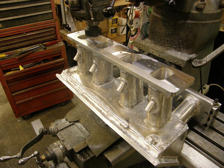
Been making more progress lately on the high riser engine, and I've almost got everything mocked up for final assembly.  A couple weekends ago I got the upper intake on the mill and machined the flanges so that they were flat and square.  I did end up having to take about .050" off each one to get them to fit properly, but when I finished the ports in the upper manifold line up perfectly with the ports in the port plates.  Here's a shot of the intake on the Bridgeport:


After milling the flanges I milled the top flange flat where the cover plate bolts on.  Part of this operation was to mill a groove in the top for an O-ring for sealing the top plate to the flange.  After I got this groove cut I took some 1/8" O-ring cord and cut it to the correct length, then butt glued the ends together; I think this is going to work out real well for sealing the flange.  Finally I drilled the holes in the flange for bolting the cover plate in place, about every 2 1/2".

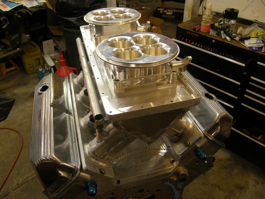
I transferred the pattern for the bolt holes to a plate of 1/2" aluminum and then made up the cover plate on the CNC machine.  On the bottom side of the cover plate, where the throttle bodies mounted, I used a 3/8" corner rounding end mill to radius the holes where the throttle bores come through the plate.  For the most part this finished up the intake; here's a photo of the manifold bolted on with the cover plate and throttle bodies set in place:


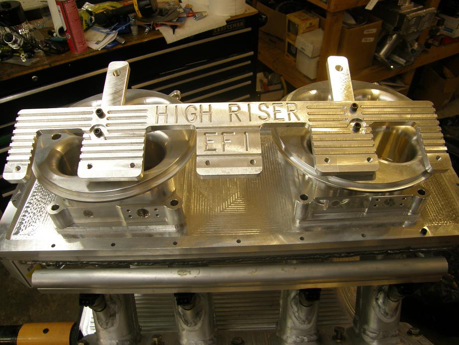
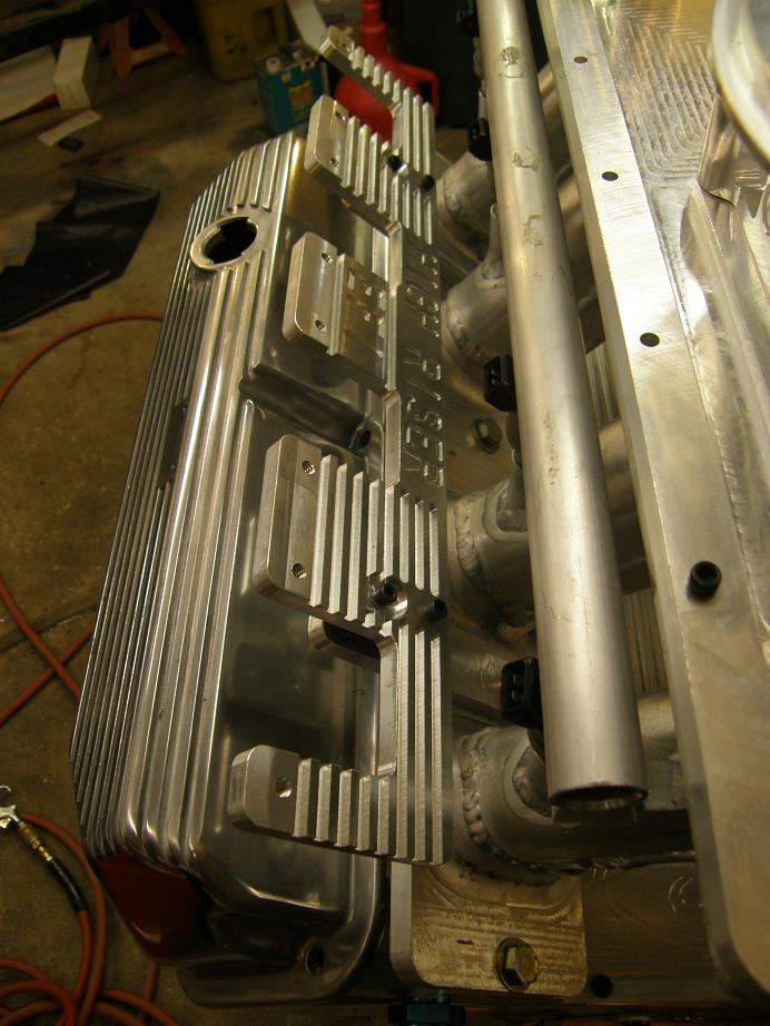
After this was done I started working on the coil mounting brackets.  This is a fairly involved part for a distributor-less engine, and I didn't want to take the normal course that most people take and mount the coils on the valve covers.  So, I designed a bracket to hold four coils on each side, and set it up to rubber mount to a couple of tabs that would bolt to two of the holes on each side of the intake.  I added some fins and some lettering the brackets to spice them up a little bit.  Here's a photo of one of the completed brackets, sitting on top of the engine:


Here's a shot showing how the brackets bolt onto the engine:


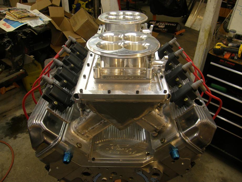
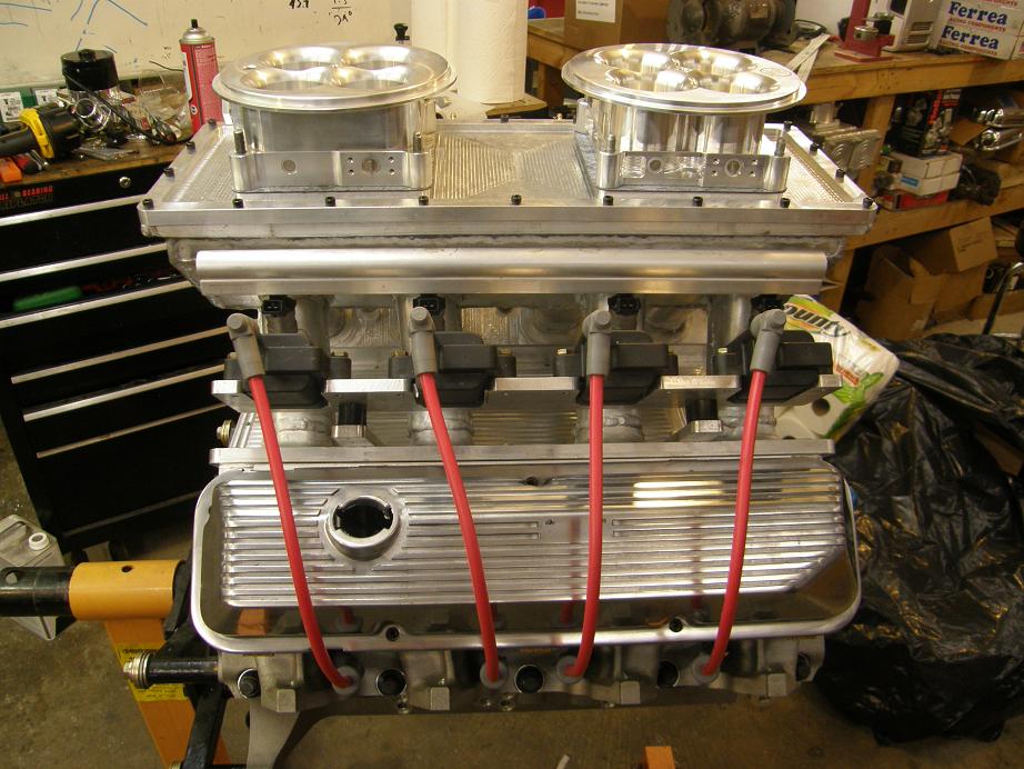
After mounting both brackets and then mounting the coils on the brackets, I decided to cut and install the spark plug wires to see how it would all look together.  Here's a couple of pictures of the engine at this point; I think it looks pretty good:


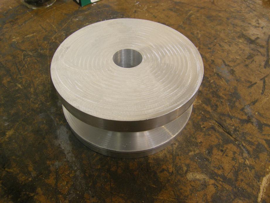
Finally, today I got started on making up some mounts for my new water pump.  I had decided to go electric a while back, but the standard Meziere electric pump wasn't recommended by Meziere for an engine over about 650 horsepower.  So, after doing a little research I decided to purchase a higher capacity pump for a 385 series Ford engine, and adapt it to the FE.  Today I took some measurements off the pump and designed a 2" thick spacer to do the job.  I started by turning a 4.5" diameter aluminum bar in my lathe into kind of a spool shape, as shown in the photo below:


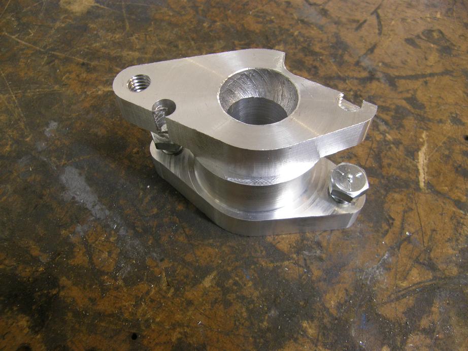
Next I stuck the part in the CNC and machined the side that bolts onto the engine block.  After flipping it over and re-indexing the part, I started machining the other side, but fairly quickly it became apparent that I had made a setup error, and was not cutting the water pump side of the spacer correctly.  I figured out the problem and fixed it, but this was going to have to be a test piece, rather than one I could use.  Here's a picture of the botched spacer:


Nevertheless, I was able to test it out for mounting purposes, and it seemed to fit pretty well.  Here's a picture of the water pump mounted on one side with the spacer:
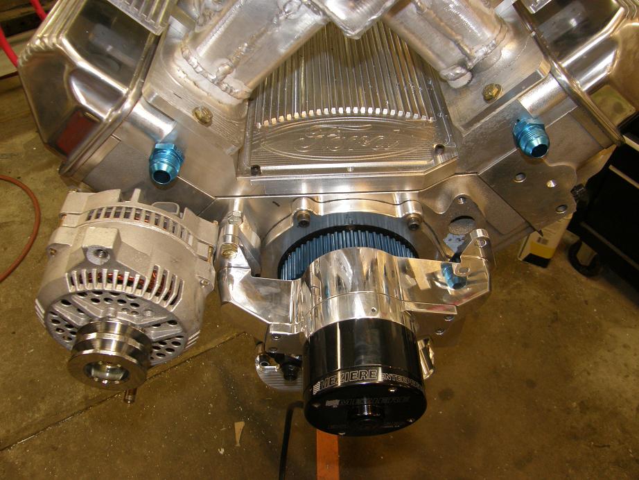


The whole engine, mocked up to this point, is shown below:


I have a plan for making the alternator bracket, and will try to start on that this week after finishing up the water pump spacers.  I also expect to be getting my Peterson oil pump in the next week or two, and have some ideas on how I will mount that on the lower passenger side of the engine.  The only other thing I need to get finished up is mounting the fuel pressure regulator and running the fuel lines, and the engine will be able to be completely assembled when the pistons arrive.

Also this week I got my new valves, which are hollow stem Ferreas that weigh 112 grams on the intake and 114 grams on the exhaust; this is about 30 grams lighter than the Manley valves I have now.  Along with the valves came the cam, springs, retainers, locks, and valve seals.  I need to get the valves ground to fit the heads and measure for pushrods once I have the valvetrain mocked up with the new valves.  But this project is moving right along, and I'm hoping to be able to dyno the engine towards the end of April.  I'll post more updates when I have them.


« Last Edit: March 04, 2012, 11:08:54 PM by jayb »
Jay Brown
- 1969 Mach 1, Drag Week 2005 Winner NA/BB, 511" FE (10.60s @ 129); Drag Week 2007 Runner-Up PA/BB, 490" Supercharged FE (9.35 @ 151)
- 1964 Ford Galaxie, Drag Week 2009 Winner Modified NA (9.50s @ 143), 585" SOHC
- 1969 Shelby Clone, Drag Week 2015 Winner Modified NA (Average 8.98 @ 149), 585" SOHC


Drew Pojedinec

  • Hero Member
  • *****
  • Posts: 2141
    • View Profile
Re: 545" High Riser Build
« Reply #139 on: March 04, 2012, 11:12:12 PM »
aww hell, now you're just showing off.


seriously, looks awesome, can't wait to hear it run!

Hemi Joel

  • Sr. Member
  • ****
  • Posts: 499
    • View Profile
Re: 545" High Riser Build
« Reply #140 on: March 05, 2012, 10:14:11 AM »
Looks great Jay!

All that machined aluminum reminds me of the old Miller racing engines.

Can you see the resemblance?


cammerfe

  • Hero Member
  • *****
  • Posts: 1676
    • View Profile
Re: 545" High Riser Build
« Reply #141 on: March 05, 2012, 03:21:06 PM »
Jay, the Jag engine for my land speed car is distributor-less and makes use of a coil-on-plug layout. The problem is that the individual coils are about the same size as your thumb and are prone to failure. I'd therefore decided to make use of the same sort of arrangement you are using. What is the source of the coils you are showing in the pictures above? Thanx!!!

KS

cdmbill2

  • Jr. Member
  • **
  • Posts: 87
    • View Profile
Re: 545" High Riser Build
« Reply #142 on: March 05, 2012, 03:40:59 PM »
Jeez Louise that stuff looks good Jay. I think you need to dress the welds on the runner tubes as they just don't match up blingwise. No knock on the welding, its just everthing else is so CNC/milled etc.

The adapted Mezeire pump idea is very cool and nicely ececuted.

Is there any need to pull water from the back of the cylinder heads to the front? I've done that for awhile now based on inut from Jon Kaase, I don't know if that applies to the version of the FE heads you are running. I've seen a lot a variation in the set-up. I have #8 lines, but I know some other very succesful guys with big Brand C engines that use #4. Supposed to even out chamber temps and eleimnate hot pockets and air bubbles.

jayb

  • Administrator
  • Hero Member
  • *****
  • Posts: 7564
    • View Profile
    • FE Power
Re: 545" High Riser Build
« Reply #143 on: March 05, 2012, 07:06:06 PM »
Jay, the Jag engine for my land speed car is distributor-less and makes use of a coil-on-plug layout. The problem is that the individual coils are about the same size as your thumb and are prone to failure. I'd therefore decided to make use of the same sort of arrangement you are using. What is the source of the coils you are showing in the pictures above? Thanx!!!

KS

I'm buying the race coils from DIY Auto Tune, www.diyautotune.com.  Here is a link:

http://www.diyautotune.com/catalog/ign1a-race-coil-p-394.html

You also have to buy the connectors for the coils:

http://www.diyautotune.com/catalog/crimp-connector-for-ign1a-p-395.html
Jay Brown
- 1969 Mach 1, Drag Week 2005 Winner NA/BB, 511" FE (10.60s @ 129); Drag Week 2007 Runner-Up PA/BB, 490" Supercharged FE (9.35 @ 151)
- 1964 Ford Galaxie, Drag Week 2009 Winner Modified NA (9.50s @ 143), 585" SOHC
- 1969 Shelby Clone, Drag Week 2015 Winner Modified NA (Average 8.98 @ 149), 585" SOHC


jayb

  • Administrator
  • Hero Member
  • *****
  • Posts: 7564
    • View Profile
    • FE Power
Re: 545" High Riser Build
« Reply #144 on: March 05, 2012, 07:15:08 PM »
Jeez Louise that stuff looks good Jay. I think you need to dress the welds on the runner tubes as they just don't match up blingwise. No knock on the welding, its just everthing else is so CNC/milled etc.

The adapted Mezeire pump idea is very cool and nicely ececuted.

Is there any need to pull water from the back of the cylinder heads to the front? I've done that for awhile now based on inut from Jon Kaase, I don't know if that applies to the version of the FE heads you are running. I've seen a lot a variation in the set-up. I have #8 lines, but I know some other very succesful guys with big Brand C engines that use #4. Supposed to even out chamber temps and eleimnate hot pockets and air bubbles.

Bill, I'm hoping that once I get done buffing the intake manifold with some of those balled up Scotchbrite pads in a die grinder that it will be closer to the bling of the machined pieces.  If not, maybe I'll grind the welds some, but I doubt I'll go that far.  Speaking of bling, I was thinking about painting between the fins on the valve covers, coil brackets, and manifold valley cover to make those parts pop a little bit more.  Maybe red, to match the plug wires?  Or Ford blue?  Or would paint in those areas be too much?

I know absolutely nothing about running coolant from the back of the heads to improve performance or even out cooling.  But if Jon Kaase does it, I'd better pay attention :D  Can you outline the performance advantages?  Is it just to keep the coolant temperatures more consistent around the chambers?
Jay Brown
- 1969 Mach 1, Drag Week 2005 Winner NA/BB, 511" FE (10.60s @ 129); Drag Week 2007 Runner-Up PA/BB, 490" Supercharged FE (9.35 @ 151)
- 1964 Ford Galaxie, Drag Week 2009 Winner Modified NA (9.50s @ 143), 585" SOHC
- 1969 Shelby Clone, Drag Week 2015 Winner Modified NA (Average 8.98 @ 149), 585" SOHC


cdmbill2

  • Jr. Member
  • **
  • Posts: 87
    • View Profile
Re: 545" High Riser Build
« Reply #145 on: March 05, 2012, 08:23:55 PM »
This stuff started with the Chevy Nascar heads years ago when they had heat issues with the center pair of exhaust ports. I first noticed it with Jon Kaase's winning Pontiac engine at Engine Masters seven years ago where he pulled waterout the back and center of the intake. he did the same on his winning 385 motor for EMC and most of the competitors do it now.

The theory covers several bases: ensuring there are no trapped air pockets at back of the engine under normal filling, and, keeping a larger volume of water flow moving more evenly across all of the combustion chambers to deal with the greater heat loads of high output engines. A lot of aftermarket heads have revised (shrunken) water passages to allow for agressive porting, varies head to head obviously. This also involved opening up some of the water passage holes in the gaskets to take adavantage of the supplemental water flow routes. Kaase has a recommended set of sizes and Cometic makes a 385 series gasket with those larger holes. The pictures below are the fittings I added at the front of my manifold and there is a similar pair at the back connected by #8 Earl's PerformoFlex hose (weighs less, way easier to fabricate)

Hoepfully some FE head experts here will weigh in on the vaibility, necessity or lack thereof.


JamesonRacing

  • Sr. Member
  • ****
  • Posts: 368
  • 1966 - What a great year for FOMOCO
    • View Profile
Re: 545" High Riser Build
« Reply #146 on: March 05, 2012, 09:22:21 PM »
Blue anodize on the valley cover and coil brackets?  Don't know that I've ever seen that done.  Would really make the Ford oval pop.
1966 Fairlane GT, Silver Blue/Black 496/C4 (9.93@133)
1966 Fairlane GT, Nightmist Blue/Black 465/TKO (11.41@122)
1966 Fairlane GTA Conv, Antique Bronze/Black, 418EFI/C6
1966 F250 C/S, Rangoon Red, 445/T19
1965 Falcon Futura 4-door, Turquoise, EF! Z2363/4R70W

jayb

  • Administrator
  • Hero Member
  • *****
  • Posts: 7564
    • View Profile
    • FE Power
Re: 545" High Riser Build
« Reply #147 on: March 05, 2012, 09:49:09 PM »
Hmmmm, anodize....  I hadn't thought about that; I was thinking more powder coating, since I already have the powder coating equipment.  Anodizing would be really cool.  I will have to look into that...
Jay Brown
- 1969 Mach 1, Drag Week 2005 Winner NA/BB, 511" FE (10.60s @ 129); Drag Week 2007 Runner-Up PA/BB, 490" Supercharged FE (9.35 @ 151)
- 1964 Ford Galaxie, Drag Week 2009 Winner Modified NA (9.50s @ 143), 585" SOHC
- 1969 Shelby Clone, Drag Week 2015 Winner Modified NA (Average 8.98 @ 149), 585" SOHC


machoneman

  • Hero Member
  • *****
  • Posts: 3859
    • View Profile
Re: 545" High Riser Build
« Reply #148 on: March 06, 2012, 08:43:45 AM »
Hey, I like all the ideas. But, blue striping and red wires might clash a tad. Your fix on how to mount the coils is a great one as it cleans up the covers a bunch and allows them to be easily seen. The Chevy LS series comes to mind as those right-on-top-of-the-covers coil packs really look dumb and almost totally hide the covers! 

On anodizing, I like that too but that would make the covers (or intake and/or valley shield) all one color and I think that might hide that nice fin work. But, I guess if say the covers were red and you carefully sanded down the fin edges you'd have that nice contrast again.   
Bob Maag

Royce

  • Hero Member
  • *****
  • Posts: 792
    • View Profile
Re: 545" High Riser Build
« Reply #149 on: March 06, 2012, 10:09:26 AM »
Jay that engine just screams "Take Me to Engine Masters".. I think I could still get you a spot.

RB
1955 Thunderbird Competition Coupe Altered Chassis "War Bird" 383 Lincoln Y block 520 hp
1955 Thunderbird 292 275 hp Y Block
1956 Ford Victoria 292 Y block

1957 Mercury 2dr Wagon "Battle Wagon" drag car 
1957 Thunderbird Glass body Tube Chassis drag car 333 cu in 500 hp Ford Y block
1961 Starliner 390/375 clone
1965 GT40 tribute w/FE
1966 Falcon Pro Touring project
Kaase Boss 547. 840 HP 698 Torque  pump gas
1992 BMW V-12 5.0
2001 Lincoln 5.4 4 cam
2000 Jaguar XK8 (Ford V8)