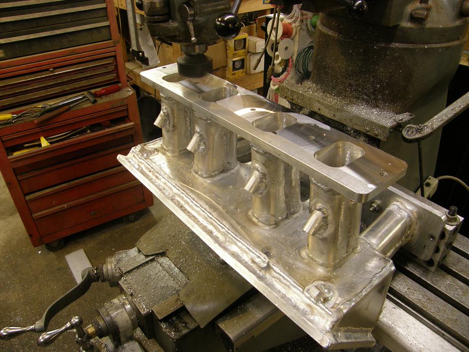
Been making more progress lately on the high riser engine, and I've almost got everything mocked up for final assembly. A couple weekends ago I got the upper intake on the mill and machined the flanges so that they were flat and square. I did end up having to take about .050" off each one to get them to fit properly, but when I finished the ports in the upper manifold line up perfectly with the ports in the port plates. Here's a shot of the intake on the Bridgeport:
After milling the flanges I milled the top flange flat where the cover plate bolts on. Part of this operation was to mill a groove in the top for an O-ring for sealing the top plate to the flange. After I got this groove cut I took some 1/8" O-ring cord and cut it to the correct length, then butt glued the ends together; I think this is going to work out real well for sealing the flange. Finally I drilled the holes in the flange for bolting the cover plate in place, about every 2 1/2".
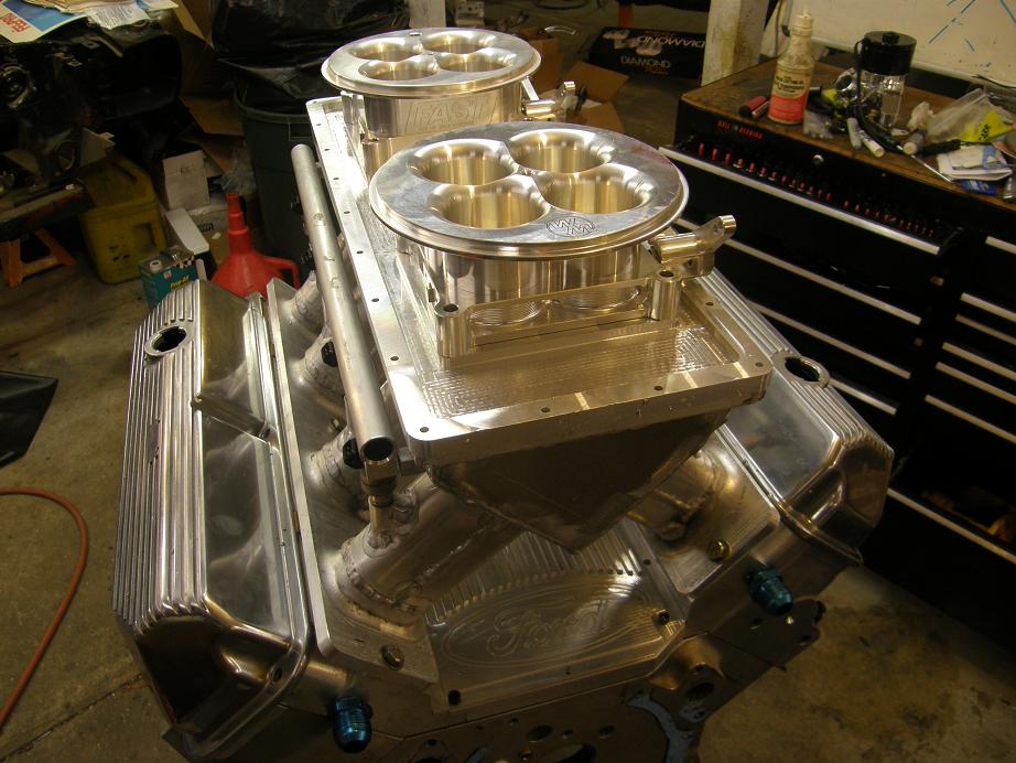
I transferred the pattern for the bolt holes to a plate of 1/2" aluminum and then made up the cover plate on the CNC machine. On the bottom side of the cover plate, where the throttle bodies mounted, I used a 3/8" corner rounding end mill to radius the holes where the throttle bores come through the plate. For the most part this finished up the intake; here's a photo of the manifold bolted on with the cover plate and throttle bodies set in place:
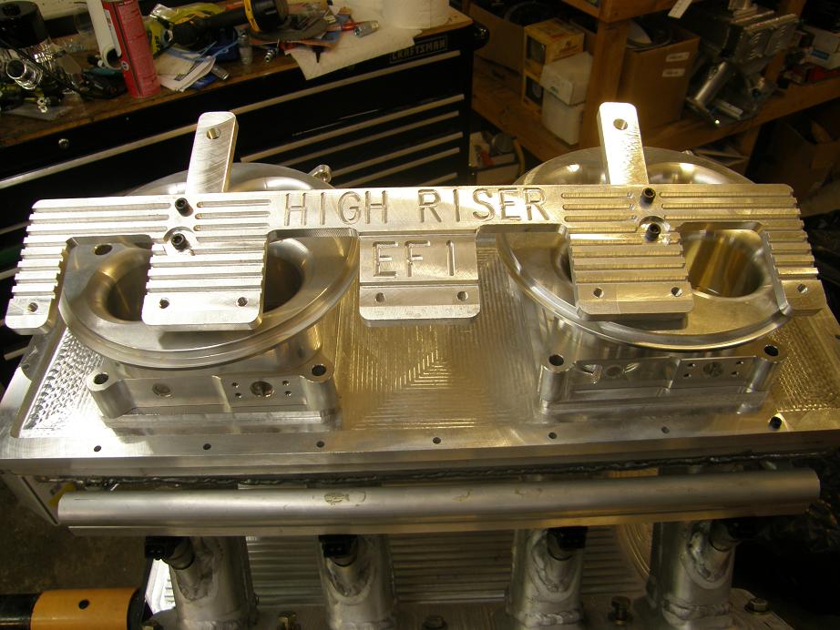
After this was done I started working on the coil mounting brackets. This is a fairly involved part for a distributor-less engine, and I didn't want to take the normal course that most people take and mount the coils on the valve covers. So, I designed a bracket to hold four coils on each side, and set it up to rubber mount to a couple of tabs that would bolt to two of the holes on each side of the intake. I added some fins and some lettering the brackets to spice them up a little bit. Here's a photo of one of the completed brackets, sitting on top of the engine:
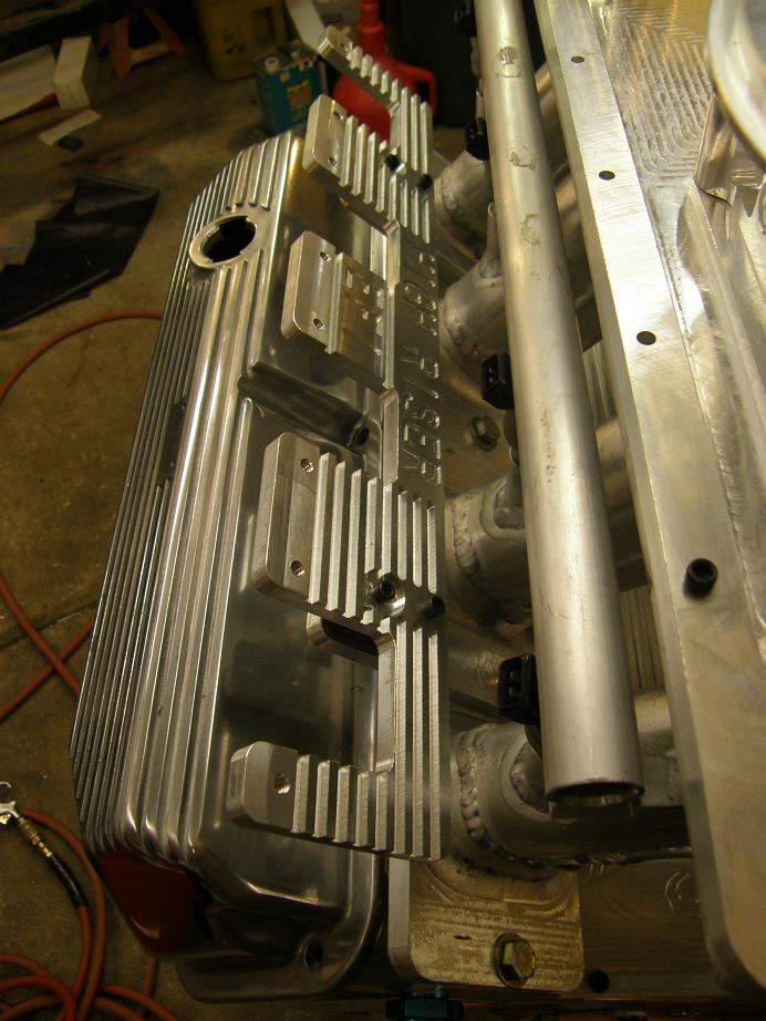
Here's a shot showing how the brackets bolt onto the engine:
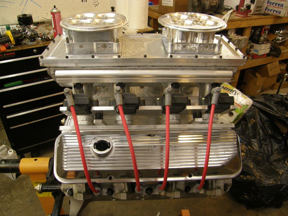
After mounting both brackets and then mounting the coils on the brackets, I decided to cut and install the spark plug wires to see how it would all look together. Here's a couple of pictures of the engine at this point; I think it looks pretty good:
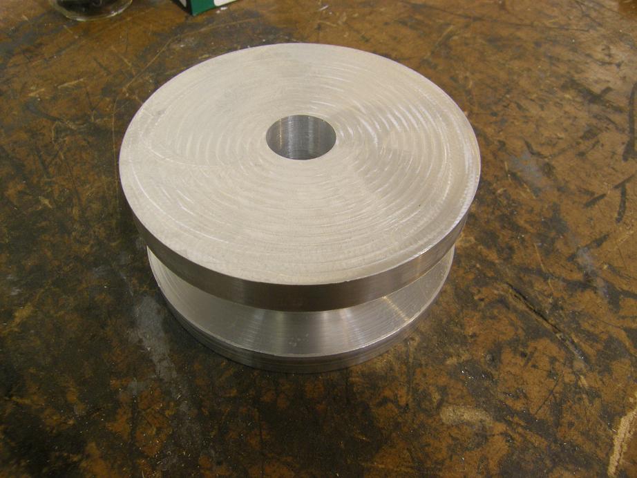
Finally, today I got started on making up some mounts for my new water pump. I had decided to go electric a while back, but the standard Meziere electric pump wasn't recommended by Meziere for an engine over about 650 horsepower. So, after doing a little research I decided to purchase a higher capacity pump for a 385 series Ford engine, and adapt it to the FE. Today I took some measurements off the pump and designed a 2" thick spacer to do the job. I started by turning a 4.5" diameter aluminum bar in my lathe into kind of a spool shape, as shown in the photo below:
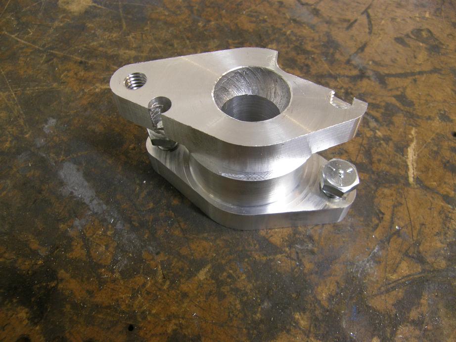
Next I stuck the part in the CNC and machined the side that bolts onto the engine block. After flipping it over and re-indexing the part, I started machining the other side, but fairly quickly it became apparent that I had made a setup error, and was not cutting the water pump side of the spacer correctly. I figured out the problem and fixed it, but this was going to have to be a test piece, rather than one I could use. Here's a picture of the botched spacer:
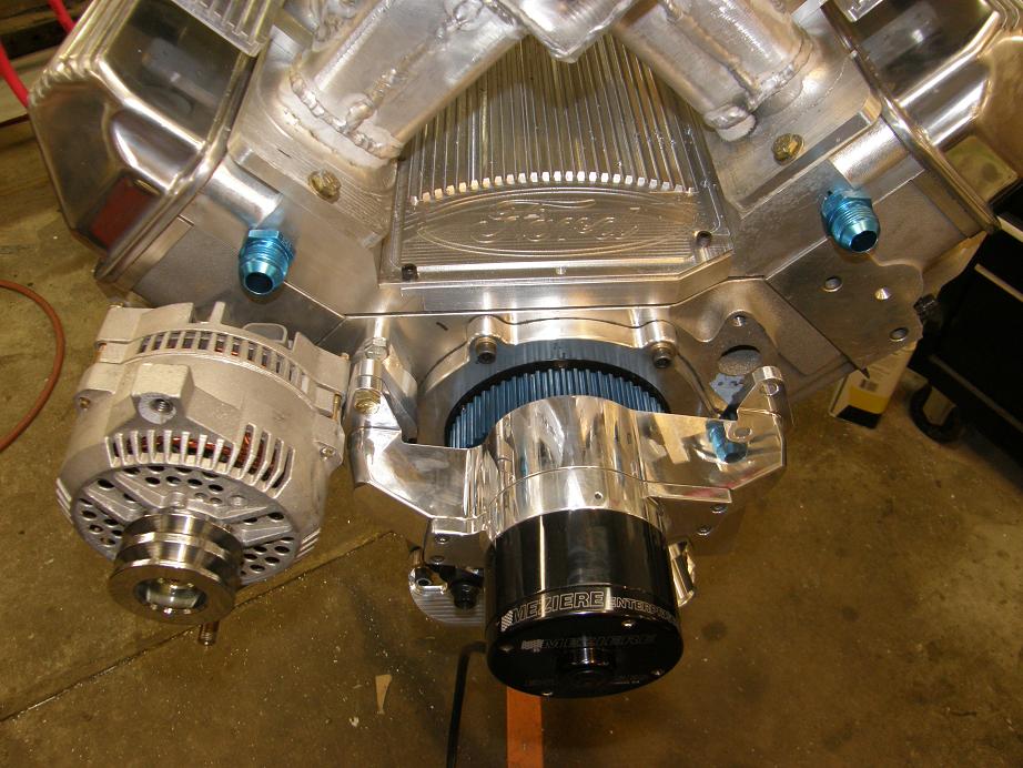
Nevertheless, I was able to test it out for mounting purposes, and it seemed to fit pretty well. Here's a picture of the water pump mounted on one side with the spacer:
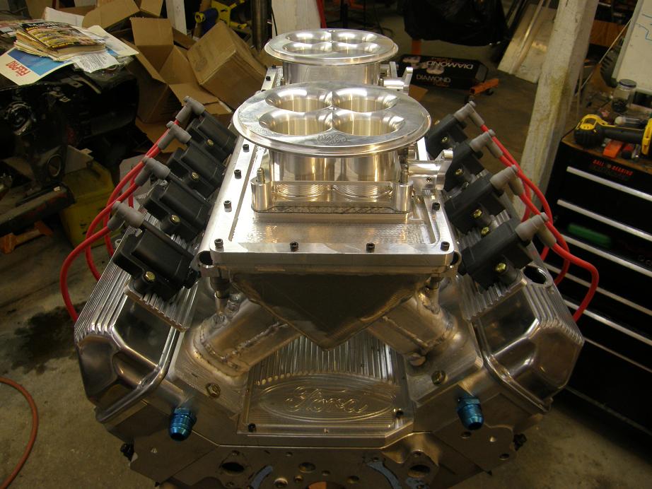
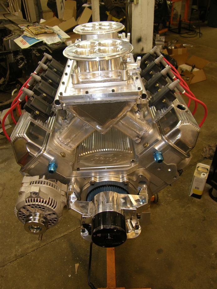
The whole engine, mocked up to this point, is shown below:
I have a plan for making the alternator bracket, and will try to start on that this week after finishing up the water pump spacers. I also expect to be getting my Peterson oil pump in the next week or two, and have some ideas on how I will mount that on the lower passenger side of the engine. The only other thing I need to get finished up is mounting the fuel pressure regulator and running the fuel lines, and the engine will be able to be completely assembled when the pistons arrive.
Also this week I got my new valves, which are hollow stem Ferreas that weigh 112 grams on the intake and 114 grams on the exhaust; this is about 30 grams lighter than the Manley valves I have now. Along with the valves came the cam, springs, retainers, locks, and valve seals. I need to get the valves ground to fit the heads and measure for pushrods once I have the valvetrain mocked up with the new valves. But this project is moving right along, and I'm hoping to be able to dyno the engine towards the end of April. I'll post more updates when I have them.


