It has been a GREAT week at FE Power. After thinking about the cylinder head project for so many years, even starting back when I did the high riser and tunnel port intake adapter, and then working on it for the last year and a half, it was great to finally have a finished head in my hands and start to get it ready to run. I am definitely having too much fun this week

Note that this is a long post with a lot of pictures, for anyone who doesn't want to read through the whole thing.
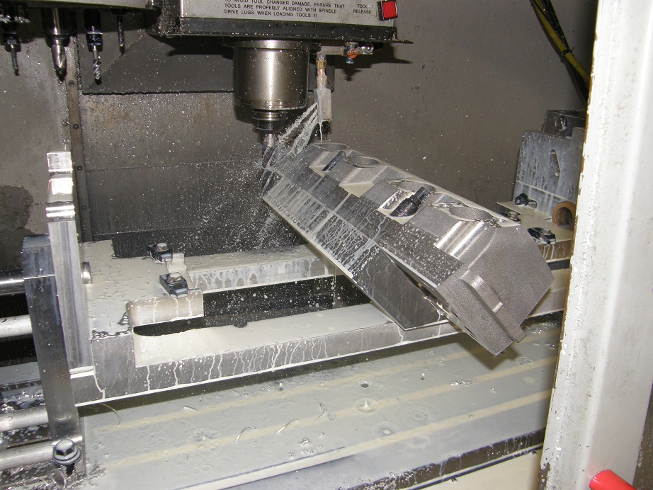
After fighting through an extended CNC machine repair in February, and then a failed air compressor a couple weeks ago, at the start of this month I was finally able to start machining the fixtures and the first head. It took me a week to write the programs and machine the fixtures required to hold the cylinder head on the rotary axis of the CNC machine, but last Thursday I was finally able to get my first head casting bolted down on the fixture. I started writing the machining programs for the head last Friday, and ran the operations one at a time as I went along to check them out. The pictures shown earlier in this thread show the head during the first operation, where most of the machining is done. I didn't finish the first operation up until Tuesday night, and as usual I made a few errors along the way, but fortunately I was able to repair these with some aluminum bolts and JB Weld, so despite the errors this head is usable. And now that I've de-bugged the machining programs, the next head should come out with no problems.
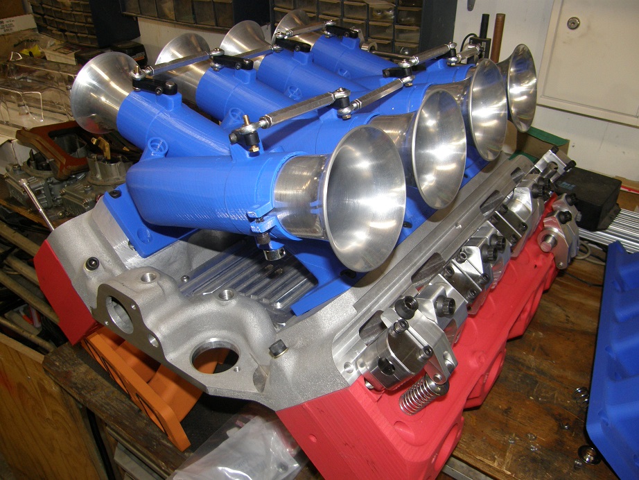
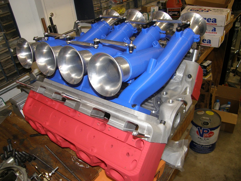
Wednesday I was looking forward to getting the head moved onto a different fixture for the second machining operation, but before I did that I made a trip down to the foundry to watch them pour the next piece needed for this project. This was my individual runner intake manifold. I had previously completed the design and 3D printed it for the PRI show; pictures below:
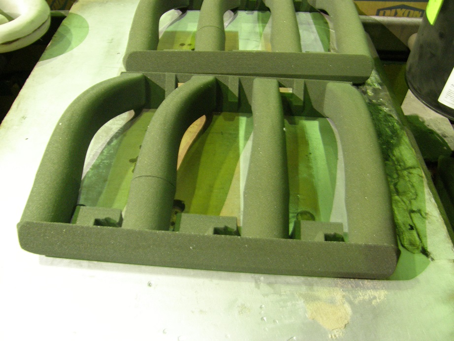
After the cylinder head casting was complete, I had the sand for the intake setup made and shipped to the foundry. They poured it Wednesday morning, following the same basic procedure as they did when pouring the heads. One thing that was a bit different on this pour was that my file for one of the runners had some kind of an error in it, and resulted in a thin gap in the core of one of the runners. There's a picture of the runner cores below, where you can see this gap:
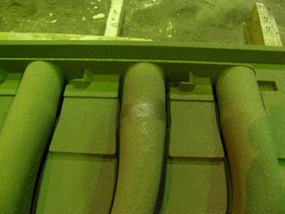
To address this issue the foundry used some kind of high temperature putty, called Core Mud, to fill the gap:
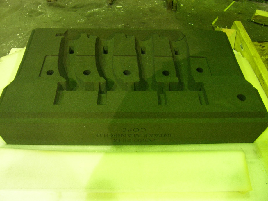
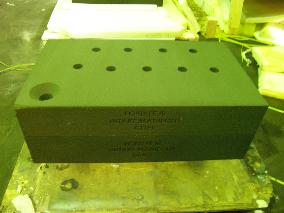
The next three photos show the drag, cope, and completed mold. This mold did not require any sleeves in the risers, like the cylinder head did, and it also did not require a chill. Again I apologize for the poor picture quality, but it is really dark in the foundry, and the flash washes out a lot of detail, so the exposure time is rather long:

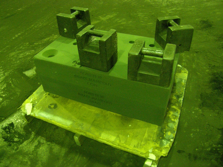
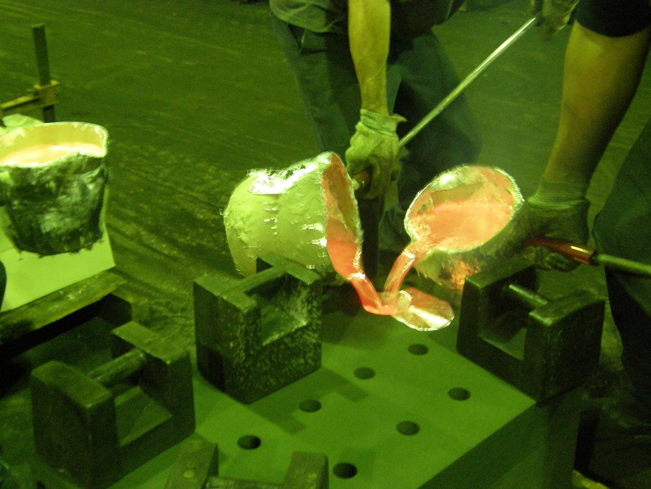
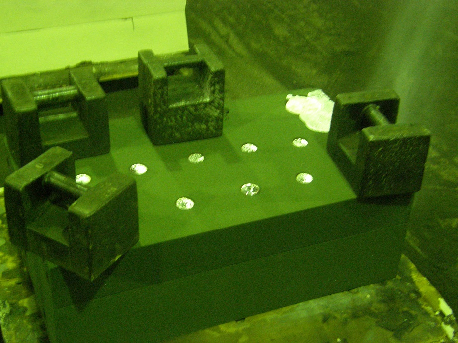
The next pictures show the mold with the lead weights on top, ready for the pour, the pouring process, and the completed filled mold:
And here is the casting broken out of the mold. It came out really looking good. I have the four runners attached together through the center with a bar; the bar is actually dimensioned on the ends the same as the cylinder head, so that it will fit right into the cylinder head machining fixture, with only a minor modification:
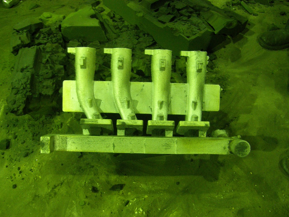
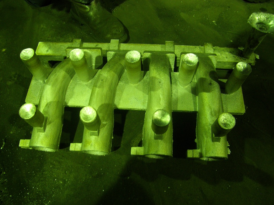
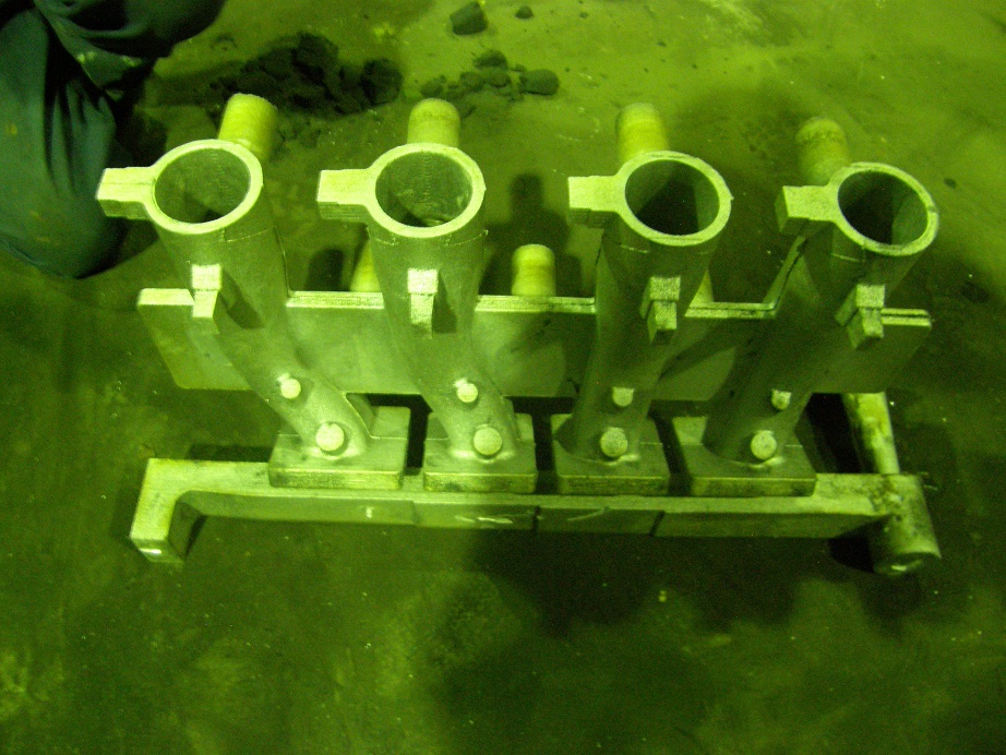
I will machine most of the surfaces on these four runners together, and then bolt them to a different fixture to cut them apart. I'm really looking forward to seeing this whole setup complete and installed on one of my intake adapters; I'm hoping to have it ready for the FE Reunion. And it sure is fun watching this stuff get made at the foundry!
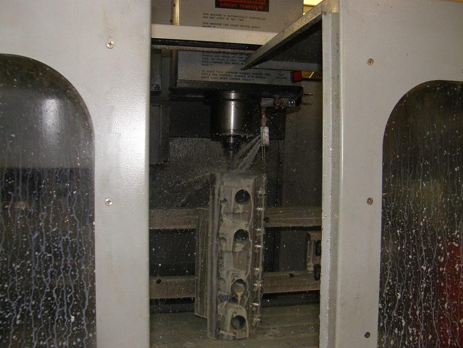
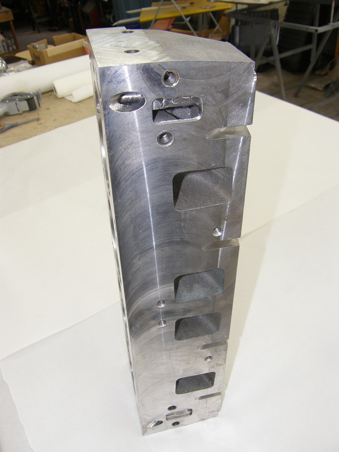
Back at the shop Wednesday afternoon I bolted an additional cylinder head fixture onto the first one; this fixture is required for the second machining operation on the head and tilts the head at an angle, in order to counterbore, drill and tap the spark plug holes. Also, with this fixture the head can be positioned vertically, so the ends of the head can be machined, and drilled and tapped for the holes in the end. The three pictures below show the head on this additional fixture, while being machined. The first photo shows the "handle" on the far end of the head being machined off. This has to be done in order to tilt the head up 90 degrees, because if the handle is still there it will actually hit the CNC table and prevent the head from rotating (I am definitely at the limits for size in this CNC machine). The second picture shows the head tilted at about 10 degrees, and one of the spark plug holes being drilled. The third picture shows the head positioned vertically and being drilled for the holes in the end:

I finished up all the machining on the head on Thursday night. Friday morning I installed the thread inserts (more on this later), grabbed the guides, seats, and valves that I had decided on for these heads and drove over to R&R Performance, where my automotive machinist friend Bryan was ready to get the head assembled. At this point, the head was still an unknown to me, and despite all the design work and research I had done over the last year and a half on how these heads should be made, I was still concerned that something bad would happen during assembly. I had concerns that the cast area around the guides would split when the guides were pressed in, or the casting would crack when the seats were pounded in, or there would be some other unknown problems that would show up. Walking into the shop I was prepared to be disappointed; it was too much to hope for that everything would be perfect on the first try.
Bryan went to work first on the guides. I had purchase some off-the-shelf guides which were a little long, so he cut them all down by 1/4" and then installed them. None of the guide supports cracked when he pounded them in, and he said it felt like they had the right amount of press. So far so good.
Next came the seat installation. I was worried about this because the seats have to go in with a lot of press, about 0.006" in most cases. They are pounded in with an arbor that indexes on the valve guide which has already been installed, in order to keep the arbor square with the seat and seat pocket. I've never watched valve seats being installed before, and I couldn't believe how hard Bryan had to hit the arbor with his small sledge in order to make them go in. At the end of each installation the whole casting would ring as the arbor was hit with a small sledge hammer. But again, all 8 seats were successfully installed with no apparent detrimental effects to the casting.
Next came a valve job on a single cylinder. The valves I had on hand were 5/16" stem, 2.350" diameter on the intake and 1.800" diameter on the exhaust. They needed to be cut down, because I wanted to set this head up with 2.300" intakes and 1.675" exhausts. Bryan cut them down to the correct size and also put a back cut on the intake valve. Next he turned to the head. On the intake, he cut the seat inside diameter out to 2.0875", which is just over 90% of the intake head diameter. When he was done, there was a nice ridge of the aluminum casting extending out beyond the inside of the seat, probably 0.100" all around. This was what I had designed for (and what everybody else designs for), to allow the area under the seat to be contoured by hand for a smooth path from the seat into the port. Everything looked good.
My luck ran out on the exhaust side, unfortunately. When the inside diameter of the exhaust seat was cut, on one side there was barely any overhang of the casting into the seat inside diameter at all, and on the other side the casting was way inside the inside diameter of the seat. Basically, the back of the seat was hanging out into the port. Somehow, I had made a mistake in the design file resulting in this issue. It was going to hurt the exhaust flow significantly.
Regardless, we'd come this far and we were going to finish this thing today. Bryan took the head into the porting room and smoothed out the area under the intake seat, and did the same on the exhaust seat as best as he could. The moment of truth had arrived: time for a flow test!
I had previously had my 3D printed plastic head flowed. I only got a peak flow number because there was no way to really do a valve job on the plastic head, and that would have had a major impact on the lower lift numbers, but that head delivered 405 cfm at 0.700" lift on a 4.25" bore. Of course, I had to take that number with a grain of salt; I wasn't 100% sure that the plastic was completely airtight, there was no plug in the chamber for that test (the hole was just blocked with clay), and the radius that I had used in place of the valve seat and valve job was an unknown. So I waited nervously, like an expectant father (LOL!) outside the flow bench room while Bryan ran the test.
The results on the intake side were all I could hope for. I think it is rather remarkable that the 3D printed plastic head flowed 405 cfm at 0.700" lift, and the aluminum head flowed 403 cfm at 0.700" lift. Peak flow was 416 cfm at 0.800", and it also flowed 416 cfm at 0.900", which showed that the port was not backing up at the higher lift numbers. This is the best flowing FE wedge head I've ever seen, besting my Blue Thunder High Risers (which were treated to about $2500 in hand porting), and this head flowed those numbers
as cast, and with a much smaller cross sectional port area. Wow, was I happy about that. Further, the inside surface of the ports is pretty rough, not as smooth as a lot of castings. I think this has to do with the 3D printed sand, it is just a much rougher texture than normal casting sand. Bryan thought that the port would pick up significantly, maybe 10-15 cfm, with just a cartridge roll smoothing of the inside port surfaces.
Predictably, the results on the exhaust side were not as good. I had been hoping for a peak of around 280 cfm, but the port just edged over 230 cfm. So, I've got some work to do on the exhaust port design yet. Fortunately for me, its only a matter of changing the port design on the computer, and getting another batch of 3D printed sand made up to test an improved version.
These flow numbers were done on a 4.25" bore, so we ran them again on a 4.375" bore to see if there was any improvement, but they were mostly the same. All the flow results are shown in the table below:
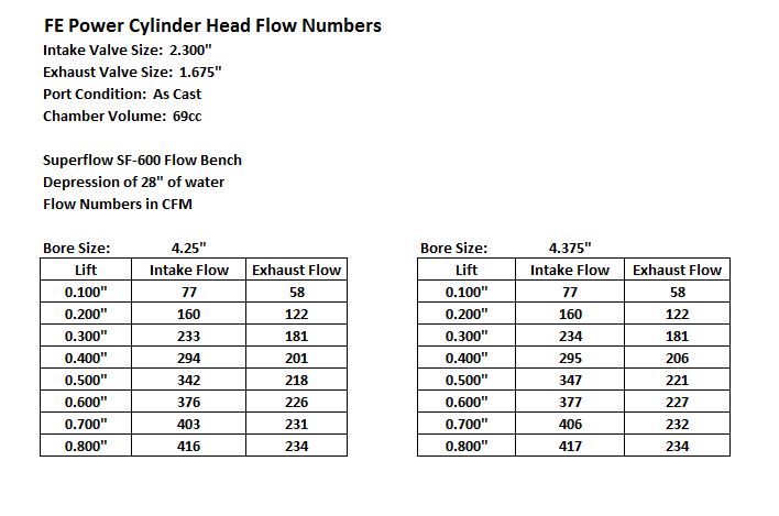
When I got home tonight I also checked the chamber volume with the valves installed and it came in at 69 cc, which is just a couple ccs bigger than I thought it would be, so that all looks good.
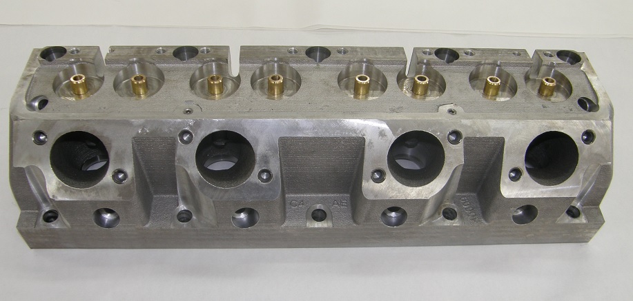
Here are some pictures of the head as it sits at the moment. First the deck surface:
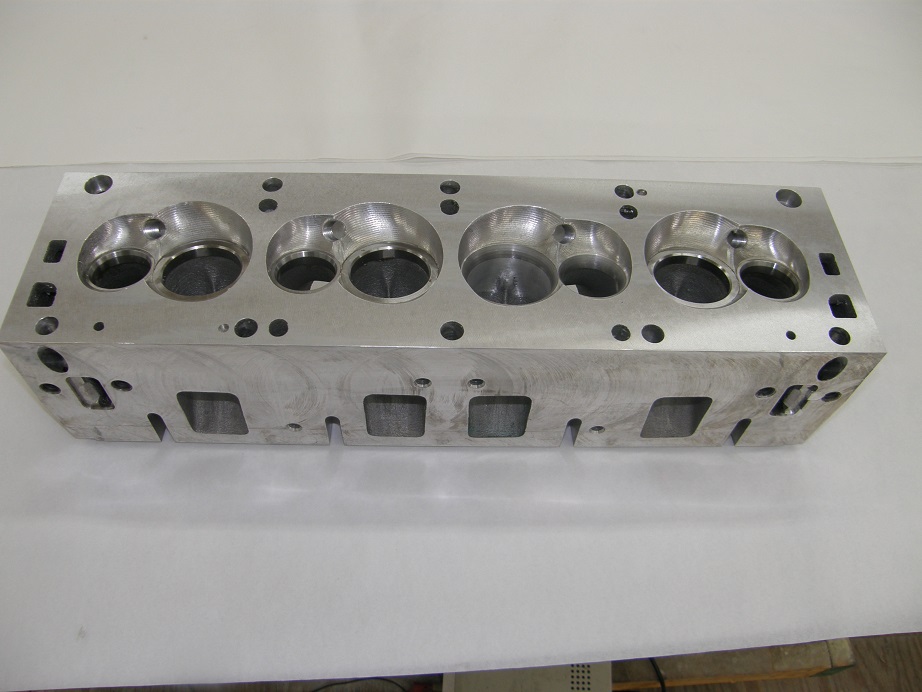
This is one of the chambers where the seats have been installed, but no valve job has been done. By the way, notice the small shallow hole to the left of the lower head bolt hole. This is a machined cavity that indexes to a pin on my fixture. It is machined to a specific depth, 0.200". Because of this machining, this hole, and one other on the other side of the head, can be used to determine how much the deck of the head has been cut in the future. Kind of like the thumbprint deal on factory heads, but much more precise.
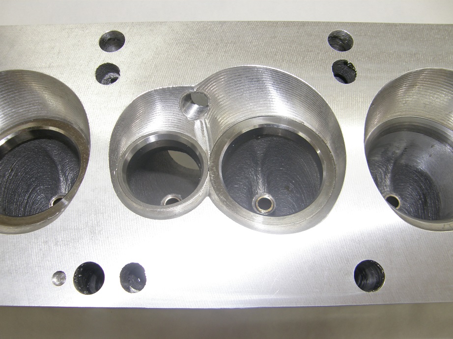
And here is the chamber with the valve job:
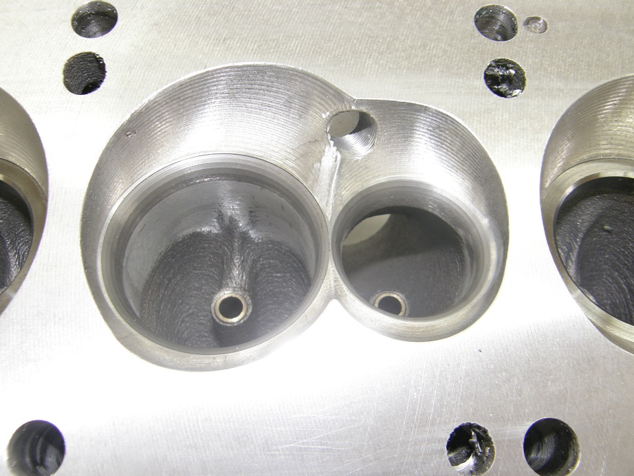
If you look closely at the intake side, up at the top towards the water jacket opening you can see two round plugs that I installed to fix a machining error. Doh! Also, you will notice the bolt holes in the end of the head. Here and in several other places I'm using an insert to prevent pulling out the aluminum threads. I thought about using Timeserts but I've had problems with those cracking on my Blue Thunder heads, so I've gone to a product called E-Z Loks. I've used these for many years now, on other heads where the threads needed repair, and have always liked how they work. Also, one other point about the bolt holes in the end of the head is that I've designed the head so that both ends use them, not just one end. I figure more mounting points for accessories are always good.
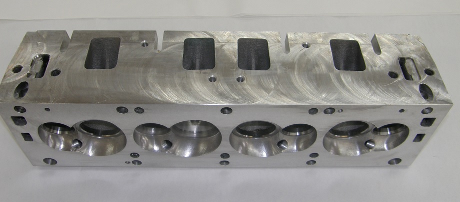
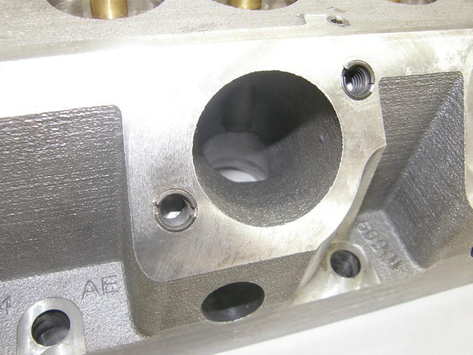
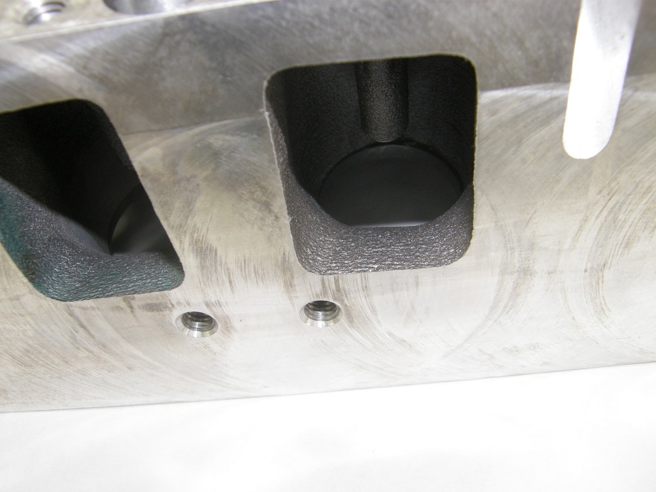
Exhaust port side:
These two pictures are close ups of the ports, showing the rough cast finish. Notice the rough surface that is also shown on the exterior of the head. The horizontal lines correspond to layers put down by the 3D sand printer. Those lines are also present in the ports, which is why Bryan figured that a little smoothing in the ports might pick up the flow.
Despite the setback on the exhaust port, the results for the intake port have me pretty excited. The intake port is far more important, and appears to be capable of supporting a 900 HP engine right out of the box, which was one of the goals for this project. I will post more pictures after I get the individual runner intake manifold machined. And I will be bringing these heads to show at the FE Reunion, for anyone who is going to see - Jay


