Sorry I'm late (as usual) with this. I have now tested a bunch of 351C intakes, including both a carbed Performer
RPM and an EFI version of the Performer RPM, provided by my pal Marc (turbohunter). We spent all day yesterday
on the EFI intake, so I could get Marc familiar with how to wire up his injectors and his throttle body, and
also how to tune the VE table (fuel map) for his engine once he gets it running. In addition to the Performer
RPM tests, I have also tested an Offenhauser tunnel ram with both dual four barrel and single four barrel tops
(courtesy of Bob Sprowl), a Parker funnel web (courtesy of Kevin Rolph), an Edelbrock Torker that I have on hand
(and took off my 68 Mustang for the tests), and a Holley Strip Dominator (courtesy of Earl). These tests
are all detailed in the post below.
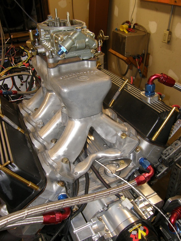
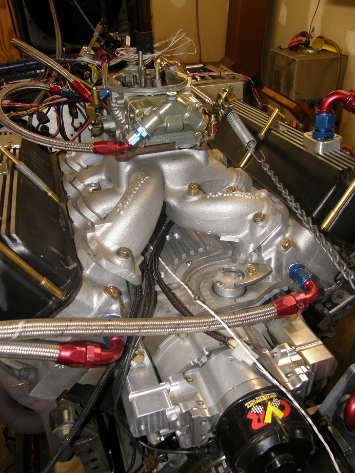
Since I had been running with the Weiand tunnel ram and two 660 Holleys, I decided to test the Offy tunnel ram
first. Here's a picture of that intake mounted on the dyno mule:
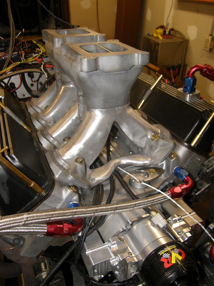
I noticed that the runners on this intake were a bit shorter than the runners on the Weiand tunnel ram, but the
plenum was way, way taller, so overall this was a taller induction system. Here's a close-up of the top of the
plenum:

Wow, Turbo-Thrust 360 Power Port! This thing had to make power LOL!
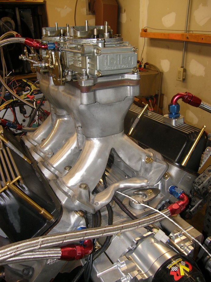
Here's a picture with the carbs mounted, this is certainly a tall induction system:
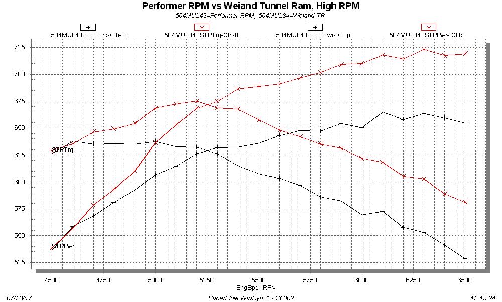
So,how did it do? Well, not as well as I'd hoped. It was down significantly from the Weiand tunnel ram. Here
is the dyno data from both the Offy and Weiand on the same chart:
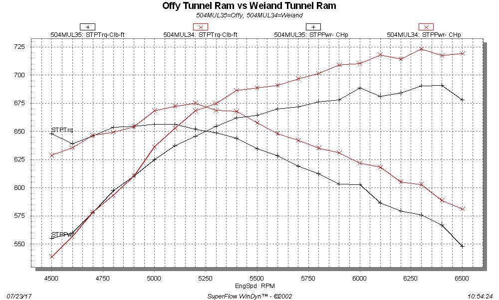
The Offy intake really seems to fall off at the top end compared to the Weiand. Still makes pretty good
power though.
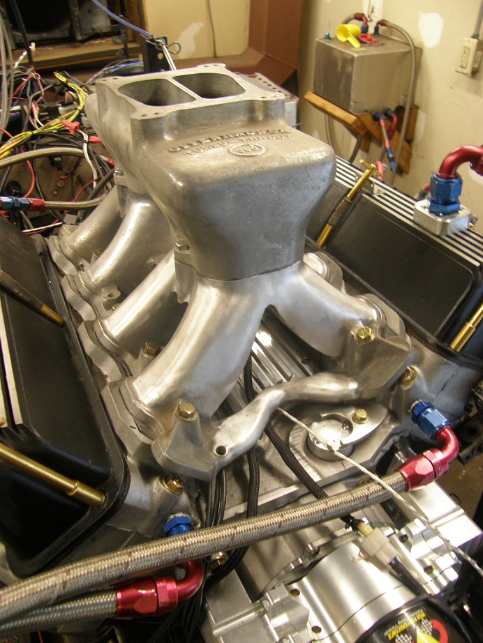
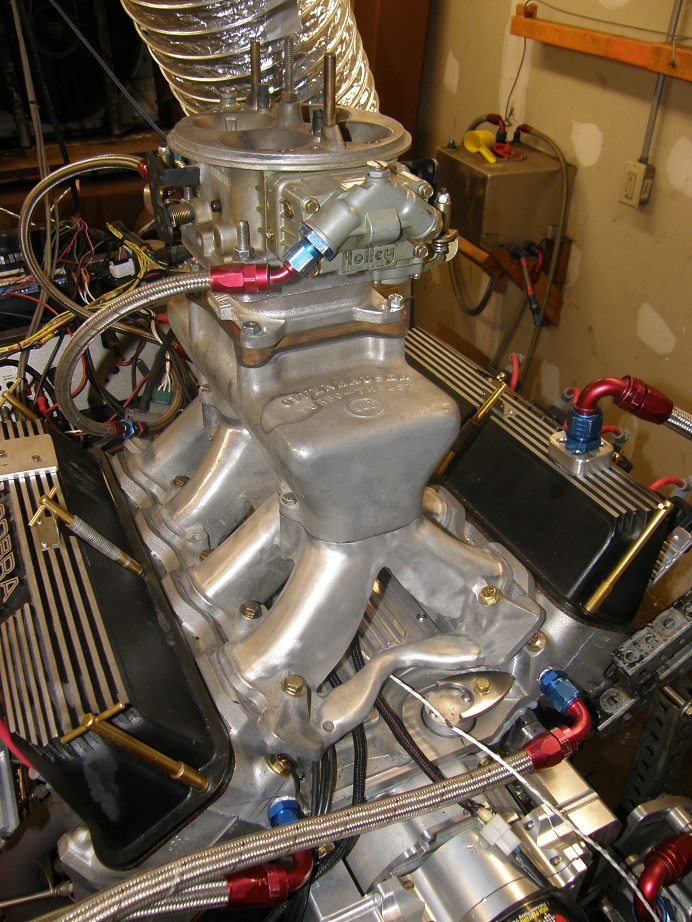
When I got the Offy intake I received two tops with it, one for the dual four barrel setup as was run above,
and one for a single four barrel. I have very little confidence in a single four carb on a tunnel ram, but as
long as I had the top I figured I'd throw it on there and test it. Here's a picture of that top mounted on
the intake:
The best 4150 carb I had here was a Holley 1000HP,so I bolted that on to the intake:
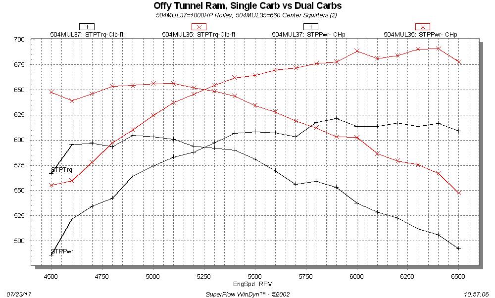
As expected, this arrangement was way down on HP compared to the dual four setup. Here is the dyno data from
both induction setups:
I was curious about the vacuum conditions under the carb; how much more manifold vacuum was there with the single
carb, as compared to the dual carb setup? Here is the manifold vacuum data from both setups:
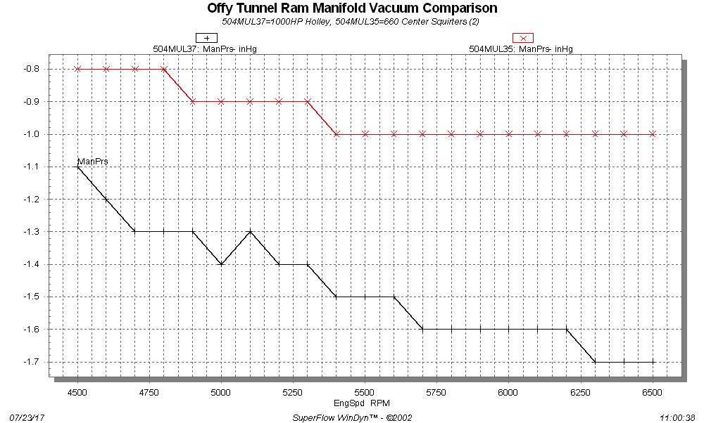
Obviously the single carb is not supplying all the air that the engine can get with the dual carb setup, but the
very large disparity in power doesn't really correlate with the difference in vacuum. I wanted to investigate
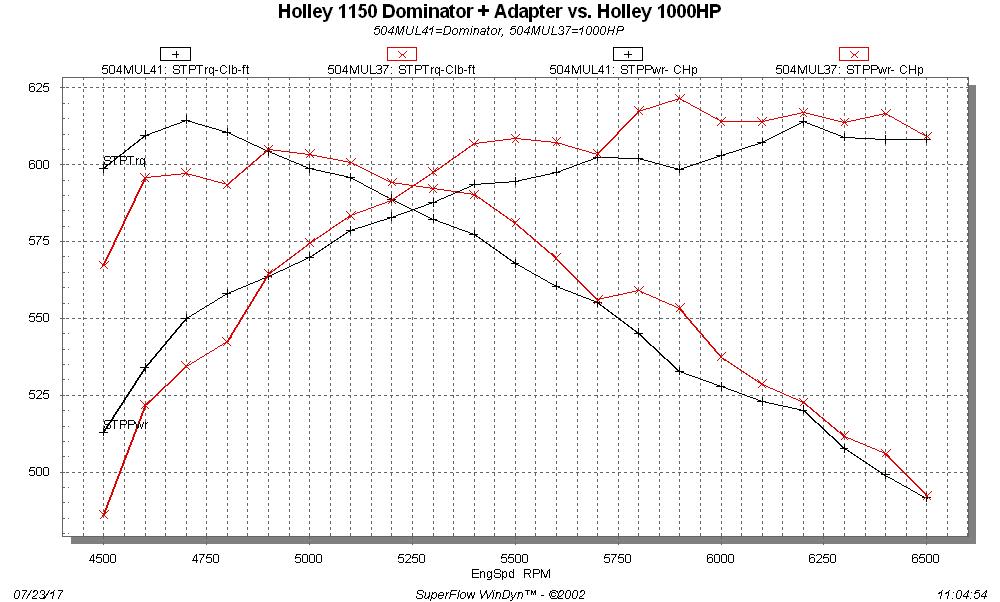
this a little further, so I borrowed one of those 4500 to 4150 carb adapters from a friend of mine, and bolted
on my 1150 Dominator carb. This is a really high induction system, now LOL:
I was certain I'd pick up some power with this arrangement, but was surprised to see that it was actually down
on power. Here's the pull, graphed along with the 4150 carb for comparison:
Next I checked the manifold vacuum conditions, to compare the dual carbs with the Dominator carb. As you can
see from the graph below, they are much closer:
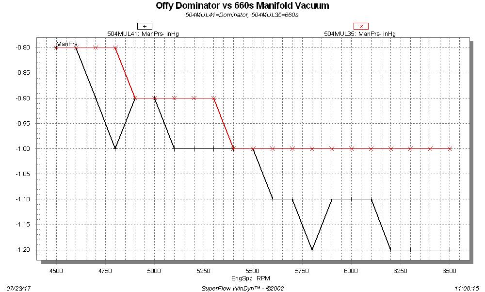
So, not to be Captain Obvious or anything, but it is clear that the intake path forced on the air due to the
central location of the single carb is really hurting the single carb plenum version of this intake. And the
additional airflow from the Dominator carb seems to be more than offset by the funnel-shaped adapter. The moral
of the story is to use TWO carbs on your tunnel ram setup.
On to the next intake. I decided to run the Performer RPM next, first because I had it just laying around and
was easy to bolt on, and also because the following day Marc was going to be here with his EFI version, and I
wanted to be able to compare the two. I used the same 1000HP Holley carb as was used on the Offy tunnel ram.
Here's a picture of the intake on the engine:
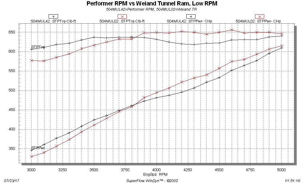
I was expecting a big power loss compared to the tunnel ram, but it wasn't as big as I thought it would be.
In fact, from 3000 RPM up the engine made over 600 foot-pounds of torque with this intake, and early in the
pull it made more torque than the tunnel ram. Edelbrock really seems to have these Performer RPM intakes
dialed in. Here's a couple of dyno graphs for the Performer RPM, with the Weiand tunnel ram also shown. Note
that in the first graph, the tunnel ram was on the engine when it was equipped with the 1-3/4" primary Hooker
headers, which made more low end torque than the Hooker adjustable race headers that are on the engine now. So,
the Performer RPM would look even better down low with the smaller primary headers:
I thought that performance was very, very impressive for a dual plane intake. My opinion was reinforced when I
tested the next intake manifold, the Parker Funnel web. This intake just looks badass; here's a picture of it
on the engine:
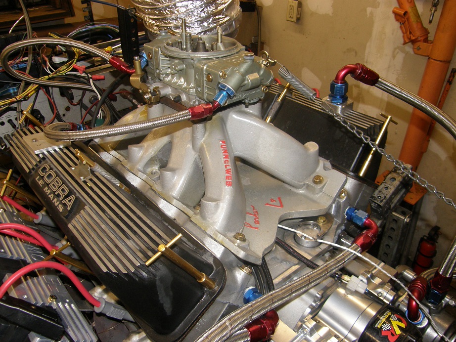
Note that this intake wasn't port matched for the testing (and neither was the Performer RPM in the previous
test), and I don't know how well the ports match up to the ports on the adapter. The intake didn't do badly,
but I was expecting over 700 HP from this intake, and didn't get it. Here is a graph of the dyno results
showing a total of four dyno pulls, comparing the Performer RPM and the Funnel Web across two ranges, 3000 to
5000 RPM, and 4500 to 6500 RPM:
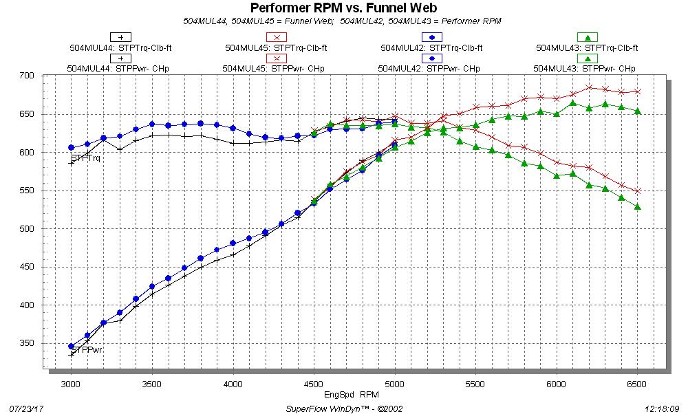
Peak HP with this intake was 685, and peak torque was 650. As expected the Performer RPM beat it down low, but
around 4500 RPM the single plane Funnel Web took over. Typical single plane vs. dual plane performance. The
surprise to me was how well the Performer RPM hung in there compared to the funnel web.
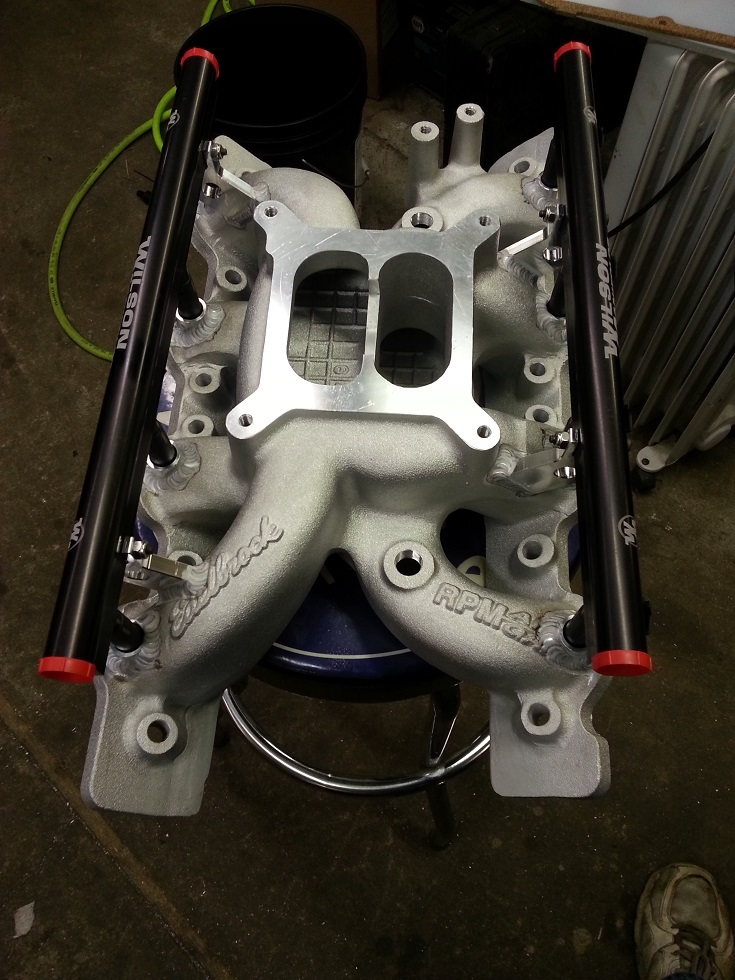
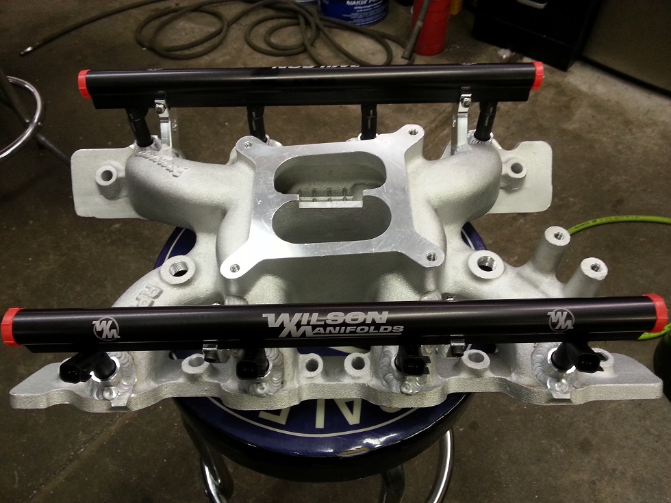
On Saturday I got a visit from our forum member turbohunter, who had previously sent me his Performer RPM intake,
outfitted with an EFI setup from Wilson manifolds. I think they did a beautiful job on it; here are some pics
of Marc's intake:
Marc and I had been talking prior to his visit, and since I didn't have a 4150 throttle body that would fit his
intake, Marc ordered one to arrive in time for the dyno testing also. The one he got was a Holley throttle body,
which seems like a really good deal compared to the other ones on the market. I have often wondered how long
companies like Wilson and Accufab can continue to sell their throttle bodies for these outrageous sums of $600
or $700; they are a lot less complicated than a carb, and just as expensive. Holley seems to have cut them off
at the knees with this throttle body, which according to Marc was around $350:
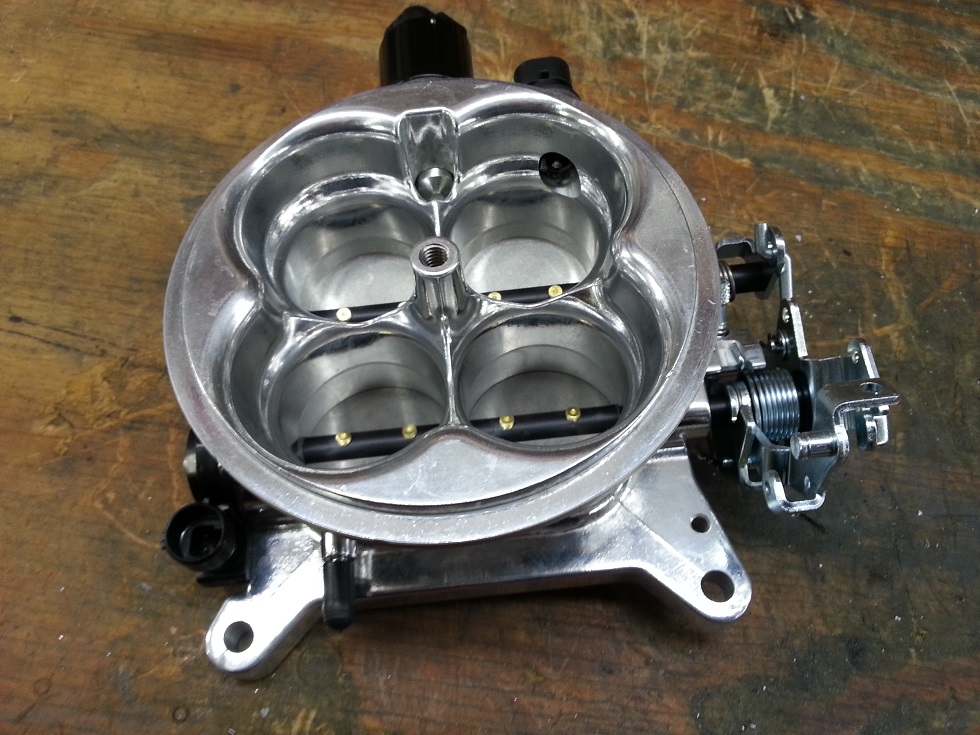
This throttle body also includes the TPS (throttle position sensor), IAC (Idle Air Control valve), and the
ATS (Air Temperature Sensor). The only thing it didn't come with was wiring connectors for those items, but we
fixed that with a quick order from Summit.
When Marc and his brother Ryan arrived on Saturday we got his intake installed on the dyno mule and then set to
work wiring up the TPS and the injectors. For the ATS, we just plugged in my wiring to the Holley throttle body,
and we used the throttle stop in the throttle body rather than fuss with the IAC on the dyno (Marc will have
plenty of time to do that later). The following two paragraphs describe briefly what's required to wire the TPS
and the injectors.
The TPS is simply a potentiometer, if you happen to know what that is. It has three connections, three wires
coming from the plug that snaps into the TPS. If you check the electrical resistance between any two of the
wires with an Ohm meter, you will find either no change in resistance when the throttle is opened and closed,
or you will see a change in resistance. To wire the TPS first find the two wires that do not change in electrical
resistance when you open and close the throttle. Those two wires are power and ground for the TPS. The third
wire is the signal wire. The signal wire has to be connected to the "TPS in" wire, which is a blue shielded wire
from pin #9, coming from the white connector on the MS3-Pro. For the other two wires, one should be connected to
Sensor Return, pin #18 from the white connector, and the other should be connected to 5V+ VREF, pin #8 from the
white connector. See the pinout listing earlier in the thread. It doesn't matter which of the two wires goes
to Sensor Return, and which one goes to 5V+ VREF; either way will work. This will be configured in the software
later.
For the injectors, the connectors that snap on to the Ford Racing injectors have two wires each. Each connector
has one black wire and one red wire. I'm pretty sure that the color code doesn't matter, but in any case I
always hook the red wires to the 12V battery supply, because that seems intuitive. All 8 of the red injector
wires are connected together, and run to the fuel pump relay (see the wiring diagram earlier in this topic).
The black wires from the injector connectors are wired into the MS3-Pro injector wires. These are 8 white wires
with various stripe colors that come from the gray connector on the MS3-Pro, pins 1, 2, 4, 6, 8, 10, 11, and 12.
These wires are labeled Injector Out A, Injector Out B, C, D, etc., all the way up to H. This is the same
scheme that the coil wires were labeled with, and in the same way, the A-B-C-D-E-F-G-H sequence has to line up
with the FE's 1-5-4-2-6-3-7-8 firing order. So, Injector Out A has to go to the injector feeding cylinder #1,
Injector Out B has to go to the injector feeding cylinder #5, etc.
It took us an hour and a half or so to get the intake installed and the wiring finished. Next, we had to
configure the software to work with our setup. I opened Tuner Studio, hooked up my laptop via the USB cable
to the MS3-Pro, and turned on the ignition switch so that the laptop was connected. At the top of the menu bar
is Tools; click on Tools, and then click on Calibrate TPS in the sub-menu. The screen that comes up will look
like this:
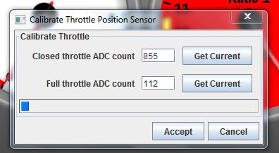
We closed the throttle completely against the idle stop, and then clicked the Get Current button. The number
in the box will change to what the MS3-Pro is reading at that point. Then, go to wide open throttle, and click
the Get Current button next to the Full Throttle line. Again, the number in that box will change. Click Accept, and you are
done. However, when Marc and I did this, we got a warning that our closed throttle number was higher than our
full throttle number. We could have changed that by switching the Sensor Return and 5V+ VREF wires to the TPS
sensor. But its not necessary to do that, the MS3-Pro compensates either way. So we OK'd the warning. On the
Tuner Studio dash I have a gauge that shows throttle position, based on the TPS sensor. Now with the throttle fully closed
the gauge read 0%, and with it wide open the gauge read 100%, so we knew that everything was working.
Next we went to configure the fuel injection system; up to now of course I've been focused on ignition parts of
the MS3-Pro. However, at the very beginning I did use the required fuel calculator, shown earlier in this
thread. The injectors I will be using for much of the testing are 65 pound/hour injectors, but Marc was set up
with 60 pound per hour injectors. So, we had to go back to Engine and Sequential Settings, under the Basic/Load
Settings tab, and re-run the Required Fuel calculator. We also set up the engine for full sequential operation;
see the computer screen shot below:
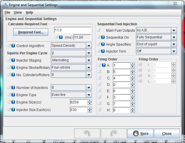
Notice that Fully Sequential is selected in the Sequential On box. Also, Injector Trim is set to off, so that
all the injectors are squirting the same amount of fuel. For really fine tuning, you can turn this on, and
adjust each injector individually, to provide the exact amount of fuel that each cylinder requires. I've done
a little experiementation with this with an O2 sensor in each primary tube, and you can pick up a little power
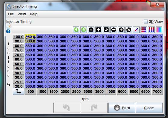
that way. Finally, Angle Specifies is set to End of Squirt. This can be changed to Middle of Squirt or
Beginning of squirt. The angle is defined as the degrees of crankshaft rotation past TDC on the firing stroke,
and the MS3-Pro instructions say that it is typically set so that the end of the squirt occurs just before the
intake valve opens. The default value is 360, and is set for various fuel loads and RPM, using the Injector
Timing table, which is under the Fuel Settings tab. For our testing with this intake we just left everything at
the default values. Here is what the Injector Timing table looks like:
The other part of the configuration is in the General Settings menu under the Basic/Load Settings tab. We set
up the parameters as shown in the screen shot below:
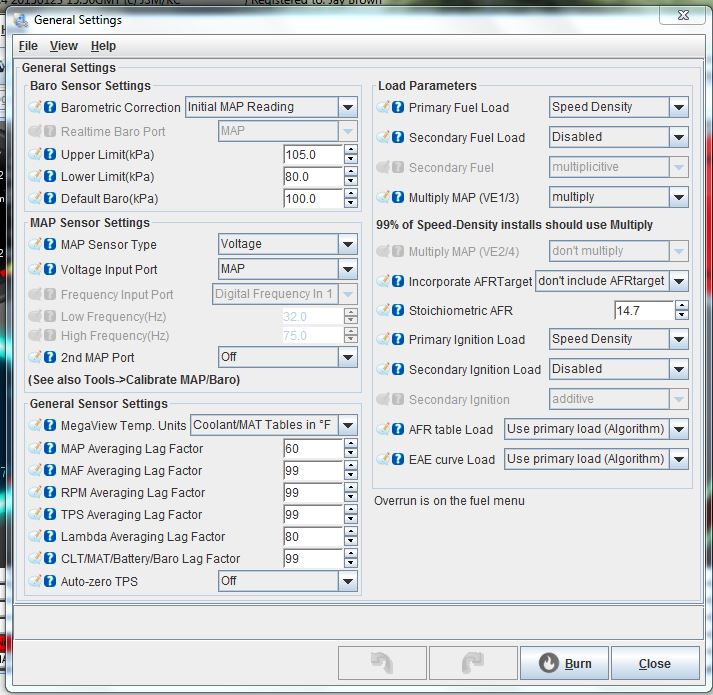
Some of the parameters, for example the ones under the General Sensor Settings at the bottom left, are just copied
from the settings in my other EFI cars, and I really don't have any experience changing them. I rely on my friend
Scott Clark to know the correct settings there, and that's how he set those up. But the Load parameters on the
right hand side are important; you need Speed Density in Primary Fuel Load, Multiply in Multiply MAP, 14.7 in
Stoichiometric AFR, Speed Density in Primary Ignition Load and Use Primary Load in AFR Table Load and EAE curve
Load. Secondary Fuel Load and Secondary Ignition Load are disabled because we are not using a blended fuel
table (which is a whole 'nother animal). Finally, we set Incorporate AFR Target to Don't Include AFR Target;
this means we are running open loop, and tuning the system ourselves, rather than running closed loop, and
having the computer correct the fuel table to some specific A/F value. As we will see later, running closed
loop would have very likely caused us some trouble with this installation.
With the General Settings menu completed, we were now ready to fire the engine on the injectors. I cranked it
and gave it a little throttle, and it fired right up. It was running kind of rough at first, which is normal
for these setups because there hadn't been any tuning done in the VE (fuel) table, and the initial settings that
are put into the MS3-Pro are extremely rich. I think they figure that you are better off running rich at first
than running lean. Anyway, while the engine is cold there are also other parameters at work to change the fuel
calculation; for example, there is a table you can modify to add fuel when the engine is cold, kind of like a
choke would make the engine run richer. Before starting the tuning its a good idea to get the engine warmed up
to normal operating temperature so that any temp related enrichment is finished.
Once the engine was warmed up and running at around 1600 RPM, I started making changes to the VE table. A
screen shot of the starting VE table is shown below:
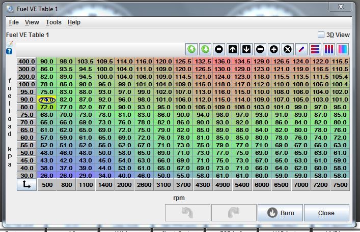
The blue oval on the VE table shows where the engine is operating at that particular moment. With the engine
more or less stable at 1600 RPM I started changing the numbers in the boxes in that area, while watching the
A/F readout on the main Tuner Studio dash. I was taking the A/F numbers with a grain of salt, because this
engine has a big cam, which can tend to fool the wideband O2 sensor, and also the dyno's exhaust is not perfectly
sealed. However, we were reading about 9.2:1 for A/F, and the engine sounded really fat, so I started reducing
the VE table numbers. We moved the engine RPM around some and made changes to 3 or 4 different spots on the
VE table. Then, we tried to fill in the areas between these spots to make a more or less continuous table.
This can be seen by looking at the color change between the cells in the table, and also by looking at the 3D
view of the table:
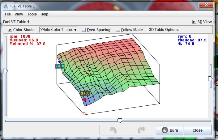
You don't want a lot of peaks and valleys in this table, you want it fairly smooth to keep the fueling of the
engine consistent. This table is far from perfect, but it gives you an idea of what you can look at in the
software to help tune the engine.
After spending some time on this we were able to get the engine running and sounding pretty good. We had a
stable idle at right about 1000 RPM, which was at least 300 RPM lower than what I could get it to idle at with
the carburetor. In addition, it seemed to rev cleanly from one point to another on the map. And it started
with no throttle input at all; just push the start button and it fired right up.
Finally we started making some dyno pulls. I will cover that in the next post, because I've had enough of
typing tonight LOL! I will try to get the remaining dyno results posted tomorrow night - Jay


