This is another one of these projects that I have been planning for a few years, and am just now getting around to. Back when I first built the intake adapters I tested a few 351C intakes on an adapter that was fitted to my 428CJ engine. But this was only a 425 HP engine, and despite being pleased with the results from the intake adapter, I really wanted to test it on a higher HP engine, along with several other 351C intakes. I started accumulating parts for a new dyno mule back then, but never ended up freeing up the time to put it together.
Over the last month I've lit a fire under this project and finally made some progress. Here is a brief rundown on the engine so far:
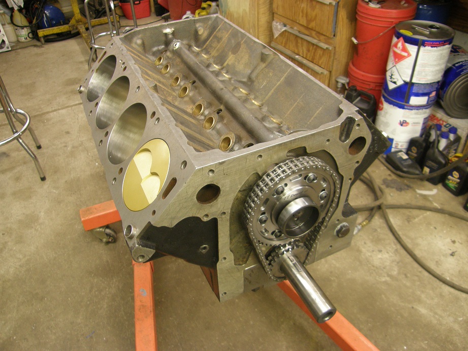
Block - This is one of Robert Pond's prototype cast iron blocks. It is the same block that I used to build my 427 dyno mule for the testing in my book. It was a blem, or a reject, that I purchased from Robert for a reduced price. The problem was that the oil gallery leading from the oil filter adapter up the front of the block to the top oiling gallery was exposed to the water jacket. Back when I purchased this block in 2006 I made a deal with Blair Patrick that he would fix the block and do all the labor at no charge, I would pay for parts, and he would get to run this block at Engine Masters. I think he ran it there in 2007, but can't remember for sure. Anyway, I got the block back from Blair and built the 427 dyno mule with it, but after all the testing and teardown I didn't like the way that the Honda rod bearings were holding up, so I abandoned that approach in favor of a stroker. The block is now 4.280" bore.
Crank - This is a forged RPM 4.375" stroke crank, from Barry at Survival. With the bore in the block the engine is 504 cubic inches. I'm using the 125M Federal Mogul main bearings.
Rods - These are Crower billet rods, 6.700" length, with BBC pins and Clevite bearings.
Pistons - These are custom Diamond flat tops, 12.75:1 compression, with a race style ring package that is .043/.043/3mm, 14 pound tension oil ring. I plan to run a vacuum pump on this engine.
Cam - This is a Comp custom grind using their ZT series lobes. Specs are advertised duration 304/314, duration at 0.050" 272/282, lift 0.723/0.735. This is a very aggressive profile.
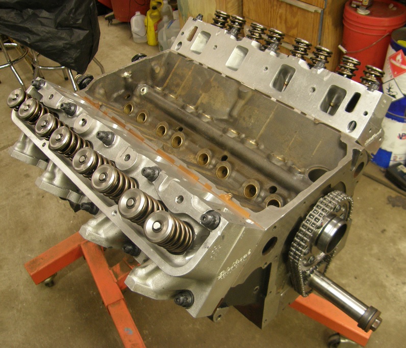
Heads - These are Edelbrock heads that have been ported by Joe Craine. When I talked to Joe about these I had them in mind for this project, and I asked Joe to try to keep the port size as close to medium riser port size as possible. This was because I wanted a test of the intake adapter with the stock port size, so I could get a good comparison of the performance of the 351C intakes if someone just bolted them on to their medium riser engine. Joe did end up enlarging the ports slightly, to 2.175" X 1.475", to get the heads to flow about 330 cfm on the intake side. I will match the ports of the intake adapter to this port size.
Right now the short block is together and the heads are on the engine; see the pictures below:
I wanted to be able to run carbed intakes and EFI intakes on this mule. Also I wanted to be able to run distributorless if necessary; this is because some of the folks who are lending me intakes to test will not want them modified to fit on the normal intake adapter, and the water jacket passage and distributor may get in the way of the 351C intake. So, the intake adapter I use will be a custom one, with the water jacket passages machined off and the water outlets drilled and tapped at the front of the adapter, on either side. I will use a remote thermostat housing to run the water lines together and connect up to the dyno cooling tower.
In light of these requirements adding the front end components to the engine is different from a normal FE. Based on my experience with EFI I have a preferred way of doing this, and some of my products are designed with this experience in mind. Hopefully this dyno mule will give any interested people a good idea of how to add a top shelf EFI system to the FE.
After getting the short block together and cam installed, first step was to add the timing set. I used one of my new billet timing sets with the adjustable top gear, because it is much easier to degree the cam than pulling and replacing the crank gear a few times to get it right, and also because as the engine runs for a while the timing chain will stretch. That will retard your cam timing, so it is easy to stay on top of this with the timing chain set that has the adjustable top gear. By the way, EVERY timing chain stretches after a while. I just pulled down one of my other dyno mules that had that top of the line Iwis German chain, and it had a ton of slop in it. Certainly that would have a significant effect on cam timing. I have never seen a timing chain that didn't stretch after a couple thousand miles, so being able to re-set the cam timing is important, to me anyway. One other reason for using this timing set is that it is easy to add a cam sensor target; more on this later.
I installed the timing set so that at top dead center on the firing stroke, the adjustment marks for setting the cam timing were straight up, to make them easier to read on the engine. Here's a photo of the timing set installed:
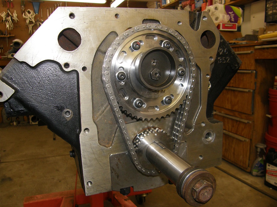
I know, I know, there's no washer on the cam bolt to hold the pin in

I will put it on later, when I degree the cam.
Next step was to install one of my timing covers with the removable front plate, for easy access to the top timing gear. This cover has some features that we will utilize later, but for now it is just bolted into position; see the photo below. Notice the aluminum sleeve on the crank; it aligns the center of the seal hole with the crank snout, so that the seal is perfectly concentric with the crank. You install the sleeve to center the holes, then tighten the timing cover bolts. I machined this part up years ago and always use it when installing timing covers. It works on stock covers or my covers:
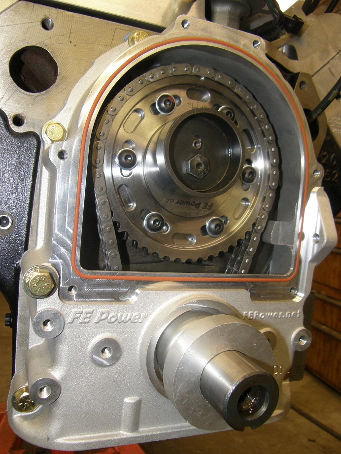
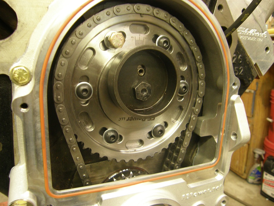
You may have noticed that one of the adjustment bolts on the timing set has a red dot on it. This is there because I am going to replace that bolt with a longer one. The longer bolt will serve as a target for a magnetic sensor that will come through the removable plate on the timing cover. This will function as the cam sensor. It will allow me to run an EFI system that is fully sequential (SEFI; fuel is injected at each cylinder, sequentially in the firing order, rather than all cylinders at once one on or both sides, like a bank fire or batch fire system). A fully sequential EFI system is generally more efficient and will idle and offer better low speed performance than a batch fire or bank fire system.
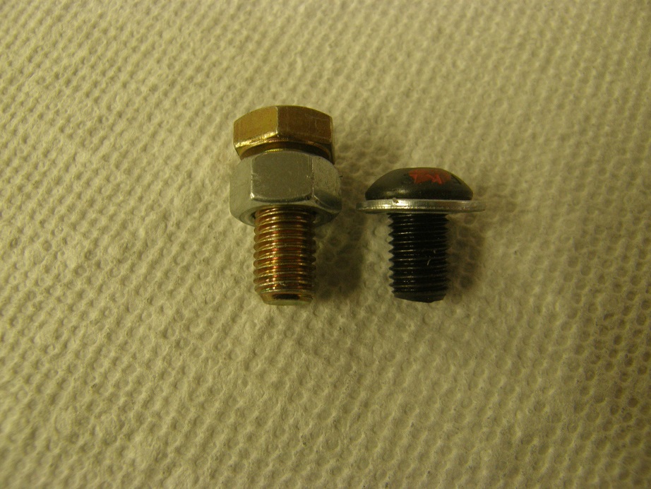
I pulled the bolt with the red dot out of the timing set, and will replace it with the bolt shown at left in the picture below. It is important to keep the length of the bolt correct; you don't want it sticking through the back of the timing gear, because it will hit the camshaft retaining plate bolts. I just used a normal six point 5/16-24 bolt with a nut on it, run all the way up to the shank:
The position of this bolt is not critical, but it must pass by the sensor and be detected sometime before TDC on the #1 firing stroke, but after TDC on the #6 firing stroke. I like to set it up somewhere between 300 and 100 degrees BTDC on the #1 cylinder firing stroke. I had already figured out the position because I knew where the cam sensor would be installed. Here's a photo of the new bolt installed in the top cam gear:
By the way, if you install this longer bolt you will not be able to use a mechanical fuel pump; it will hit the arm of the pump as it goes around. I assume that if you are installing the bolt for a cam sensor you will also be using an electric pump, required with an EFI system.
So, on to the cam sensor. I decided to use my newest product for this purpose; this is a "dress up" kit for the timing cover. It has a removable front plate made out of billet aluminum and machined with fins to add some pizazz to the timing cover. This is another product that I've been thinking about for a few years and have just gotten around to turning into a product. I just finished the first production run of these, and they will be available on the main web site in the next couple days.
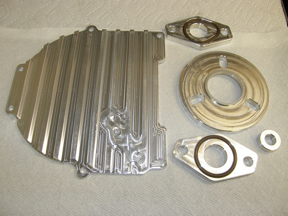
The standard timing cover comes with a 1/8" thick steel plate for the removable cover. I couldn't use aluminum because at 1/8" thick it was too flexible to seal against the O-ring in the timing cover, and if I made it any thicker it would interfere with the water pump, which is a close fit over the timing cover. As a result the new finned removable cover had to be thicker, both for the fins and also to be rigid enough to seal to the O-ring. I ended up with a 1/2" thick aluminum part, which is 3/8" thicker than the normal steel plate. So, I had to make 3/8" thick spacers available for the water pump, harmonic balancer, and alternator, in order to keep all the pulleys on the front of the engine lined up. Here is a picture of the dress-up kit, showing all the parts:
Since I had to machine the water pump spacers, I took the opportunity to groove them for O-rings, so that they could glue onto the normal water pump with gaskets, but would then allow the water pump plus spacers to use O-ring seals to the block. This allows for easier removal and reattachment of the water pump, which also makes cam timing adjustments easier.
If you look closely in the picture above, you will see three holes at the bottom of the finned timing cover plate. The first two are 10-32 threaded holes, for attaching the timing pointer. The third, top hole is not all the way through the timing cover plate; it is a starter hole for the cam sensor. To fit the cam sensors that I use, I drill the hole out to 15/32".
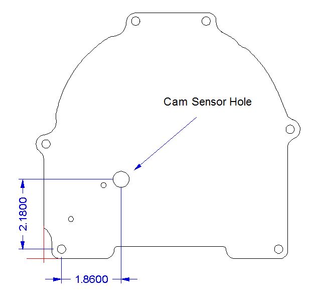
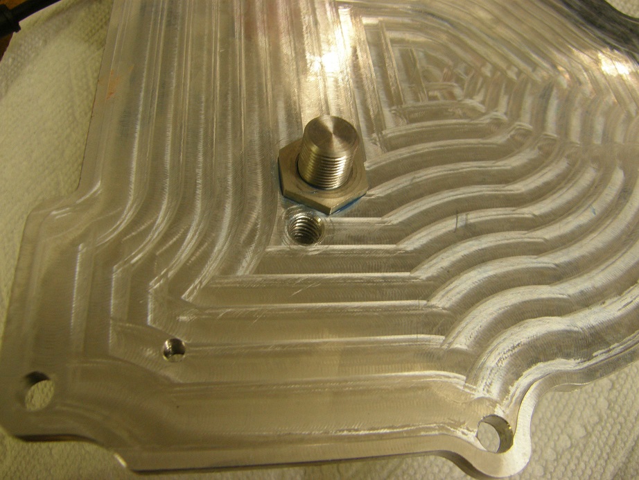
By the way, if you don't want one of the new finned timing cover plates, you can drill the standard 1/8" steel plate for the cam sensors, as shown in the picture below. The dimensions are referenced to the bottom left bolt hole in the cover, and you don't have to be exact with the hole, you could probably even be off by as much as 1/8" in either direction and it would still detect the target:
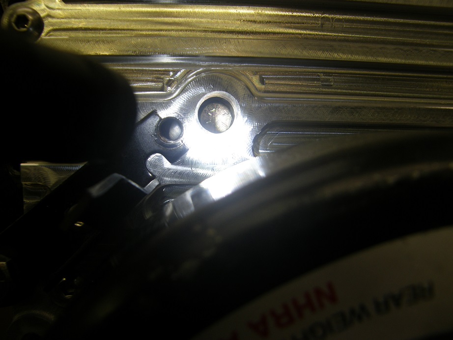
After the hole in the cover plate is drilled, you can rotate the engine around until the long bolt is visible through the hole, as shown in the photo below. At this point, the crank was at 200 degrees BTDC on the #1 cylinder firing stroke:
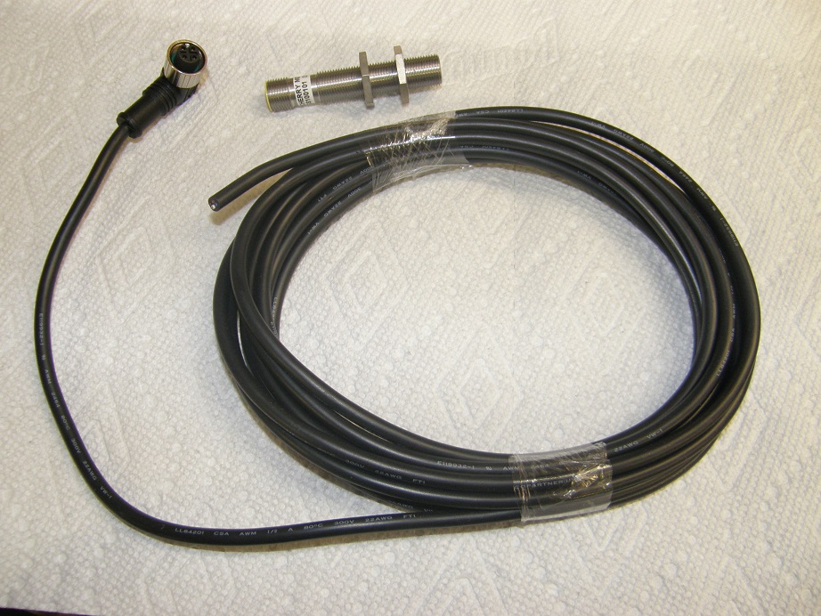
Next step is to install the sensor. Some of you may know that I spent 25 years working in the magnetic sensor business, so I am fussy about my magnetic sensors and targets. I've had the best luck with sensors from a company called ZF, formerly Cherry Electronics. These are Hall effect sensors with a threaded body, for insertion through holes. They also have a connector on the end, so that you can attach or remove a wiring cable. Here's a picture of one of the sensors and the cable:
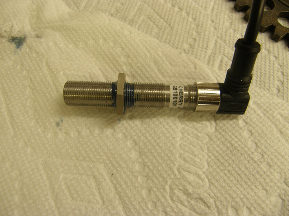
Installation of the sensor requires a 0.040" to 0.060" airgap between the end of the sensor and the target. The body of the sensor is threaded at a pitch of 0.040", which makes setting this distance easy. Here's what to do: Remove the front nut, and back off the back nut. Push the sensor through the hole in the removable plate until it bottoms against the bolt head (target). Screw the nut down until it is in contact with the surface of the removable plate, then carefully pull it out without disturbing the position of the nut. Take some blue Loctite and put it on the threads of the sensor body, just ahead of the nut, then turn the nut 1 to 1-1/4 turns towards the front of the sensor. This effectively pulls the sensor back from the target by 0.040" to 0.050". Give the Loctite 15 minutes to set up. You now have the airgap adjusted properly, but remember not to turn that nut again, or you will have to redo the procedure to get the correct airgap. Here's a picture of the sensor with the nut installed:
Once the Loctite has set up, you can push the sensor through the hole and thread on the other nut. Tighten it up with a 3/4" wrench and Loctite it in place also. Pay attention to which way the cable is facing when it comes out of the sensor; you want to avoid interference with the harmonic balancer and the water pump. Here's a picture of the other side of the removable plate, with the second nut installed:
By the way, you will notice that one of the holes for the timing pointer in the photo above is much bigger than 10-32. This was an "oops" on my part. I was starting to drill the pilot hole for the sensor and got talking with my friend Kevin in the shop, and without realizing it I drilled one of the timing pointer holes, instead of the cam sensor hole. Duh...
Anyway, I just threaded it for a 1/4-20 bolt and will use that size in that location.
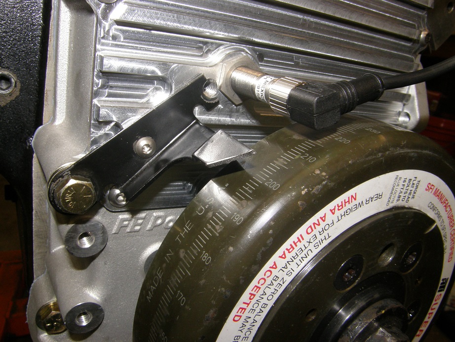
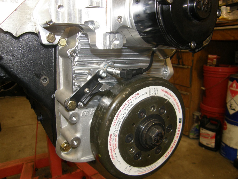
Finally, here's a picture of the plate reinstalled on the timing cover, with the sensor installed. I also installed the crank sleeve and the harmonic balancer. The direction I chose for the cable is off to the right, but I think I'm going to reposition the sensor to change that, so it goes off to the upper left instead. I think the cable could potentially droop down and hit the harmonic balancer when it is positioned like this:
Just for grins I attached and photographed three different water pumps, to document clearance between the water pumps and the cam sensor. First pump is an Edelbrock, and there is also a shot of the spacers between the pump and the block. Second is a stock FE water pump, and third is the CVR electric pump and my water pump adapters, which are what I am planning to permanently install:
Next we come to the crank sensor, which is the most critical sensor for proper operation of the engine. The sensor is the same ZF unit used for the cam sensor, but the crank sensor target and the mounting bracket are critically important in this location. Because I am fussy about this stuff, and the aftermarket crank sensor targets are not very good in my opinion, I decided to machine my own crank sensor target. The picture below shows my target on the right, and a factory Ford target (also a very good target) on the left:
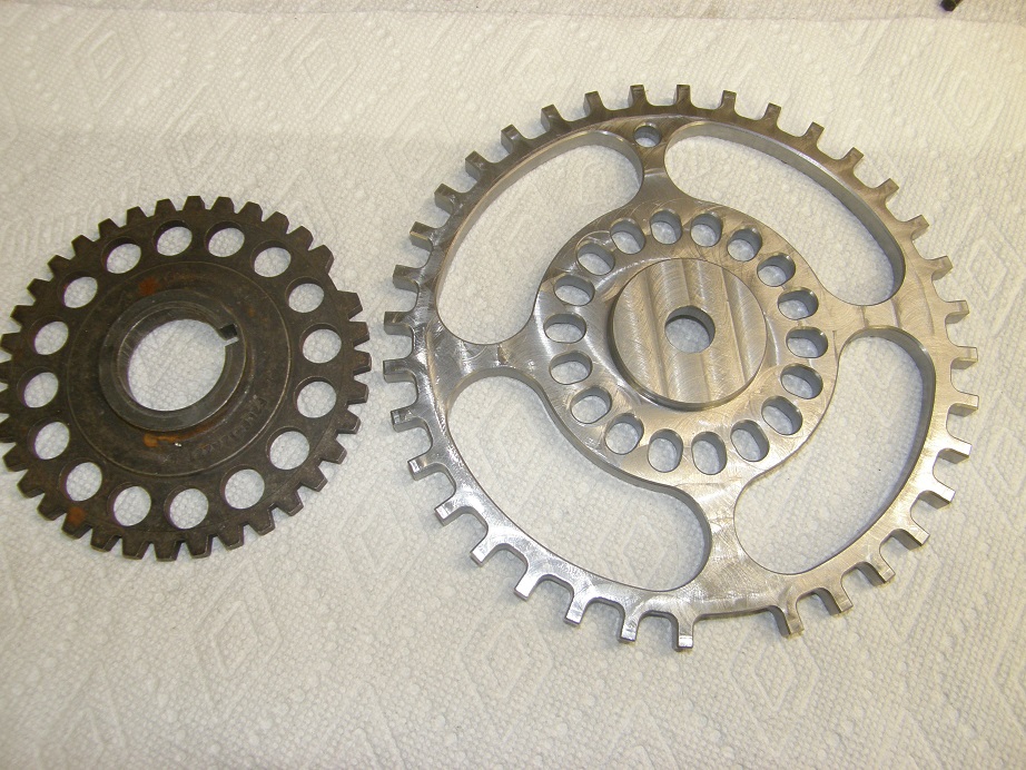
These are both 36-1 targets. This means it has 36 teeth, one every 10 degrees, but with one missing tooth. I have modified the Ford targets in the past, to work on the FE, by machining out the center of the target so that they will slide onto the crank. Then, I cut the crank spacer in half and machined part of it away. Slide on the first part of the spacer (that the timing cover seal rides on), then the target, then the second half of the spacer. This lets the target reside halfway between the timing cover and the harmonic balancer, on the crankshaft. This worked well, but it was a real pain getting in there to set the gap between the crank sensor and the target, there wasn't much access for a crank sensor mounting bracket, and it was a lot of work with the machining on the target and the crank spacer. Its much easier to just bolt the target onto the harmonic balancer, and everything is more accessible. I plan to build a production batch of these crank sensor targets in the next few weeks, so that anyone who is interested can get one.
For timing purposes it is important to know what the EFI control is seeing with this crank target. For most EFI systems, when the engine is rotating in the normal clockwise direction, the tooth that comes to the sensor right after the missing tooth, is the #1 tooth.
The EFI system needs to see the #1 tooth prior to firing the spark. Since the spark advance can be up to 50 degrees, or even more, the #1 tooth should be seen by the sensor before that. General advice on this subject is to set the #1 tooth at about 60 degrees before TDC. FE Power advice is to set it about
90 degrees. This is why: as the engine turns over on the starter, the RPM is not constant. It goes up and down a few RPM, maybe as much as from 90 to 120 or so. If you have a smaller, low compression engine, it won't vary that much. But if you have a larger, high compression engine, it can vary even more than this. It turns out that in setting the #1 tooth up at 60 degrees BTDC, you are in a part of the cranking stroke where the RPM can vary quite a bit. This makes it difficult or impossible for the EFI system to recognize and sync up to the crank target, and will keep the engine from starting. This very situation made my Shelby clone with the big SOHC extremely difficult to start in 2011, and kept me completely out of Drag Week 2012 with the car; it just wouldn't start reliably. Once my friend Scott Clark, who tunes boatloads of EFI engines, figured this out and let me know about it, I changed the position of the toothed wheel on the engine and it fires up perfectly now, every time. This hard-won piece of information has probably discouraged more new EFI users than any other, that I know of.
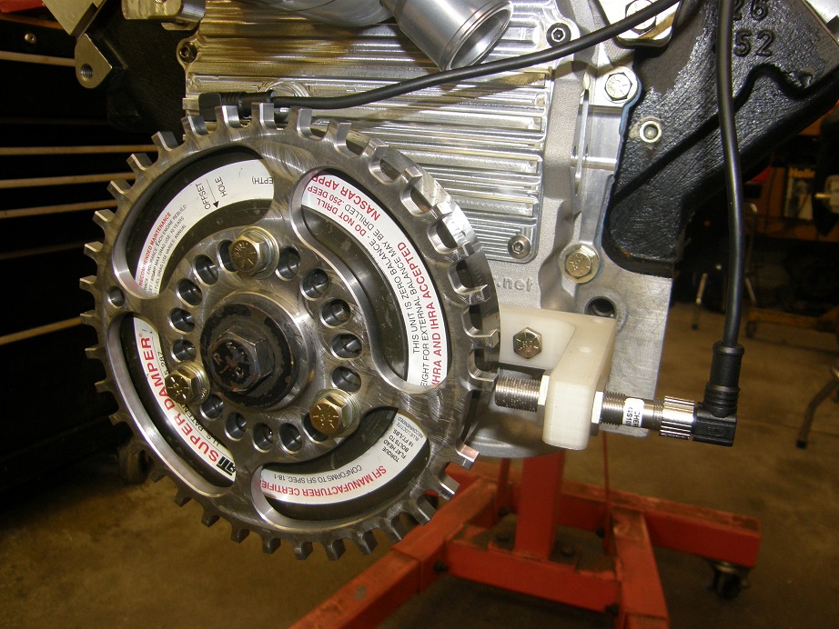
So, to recap, we want to put the #1 tooth directly across from the sensor when the engine is at about 90 degrees BTDC. Of course my balancer is fully degreed, being an ATI unit. If you are going to try to run EFI, either get a degreed balancer, or put a timing tape on your balancer, so that you can read it around 360 degrees of rotation. It makes the setup much easier. My crank sensor target has holes that are spaced at 20 degree intervals, so you should be able to install within +/- 10 degrees of 90 degrees BTDC, which is sufficient to avoid the problems previously described. On this engine I turned the crank until the pointer said 90 degrees BTDC, and put the #1 tooth about where the crank sensor was going to be placed.
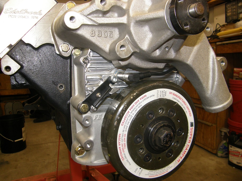
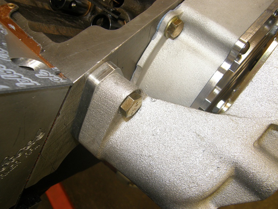
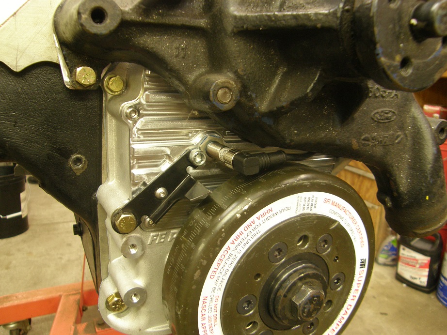
Mounting for the crank sensor is important. The mount has to be extremely solid and vibration resistant. If the sensor is moving around, the timing will be moving around. If the sensor can vibrate into close contact with the crank sensor target, the target can hit the sensor and damage it. If it can vibrate away, you can temporarily lose the signal and have a miss. I decided to make my crank sensor mounting bracket out of 1" thick billet aluminum. Before machining this, I decided to 3D print the bracket and test it for fit. This bracket bolts to two of the extra bosses on my timing cover, which are very solid and provide a good mounting point. Here's a picture of the front of the engine with the crank sensor target bolted on and the crank sensor mounted:
The crank sensor has to be adjusted for airgap just like the cam sensor; in this case you can use a 0.040"-0.060" feeler gauge to get close.
Just to recap, let's review what the EFI control unit sees as the engine starts to turn. In the software setup for the EFI unit I use (MS3-Pro) you can specify that the crank target is a 36-1 target. When you start to crank the engine, the EFI system will start to see pulses from the crank sensor, one pulse for every tooth. When it sees it's first pulse from the cam sensor, it says to itself (
), "Ah HA! The next time I see the #1 tooth, it will be 90 degrees before TDC on the #1 firing stroke!" The EFI system watches the pulses from the crank sensor and monitors how much time it takes between pulses. When it comes to the missing tooth on the crank target, there will be no pulse. This means a delay between pulses, and the EFI system says, "Hey! I'm missing a pulse from the crank sensor! That must mean that the next pulse will be tooth #1!" When the EFI system sees the next pulse, it knows that TDC for the #1 cylinder on the firing stroke is 90 degrees away. If there is 20 degrees of advance in the timing map built into the EFI system, it will then fire the #1 plug after 7 more pulses from the crank sensor. Now the EFI system is "synced" to the crank sensor target, and can calculate when to fire all the other plugs. And the engine starts.
How close do you have to be on the timing of the crank sensor? Not very. This is because the software allows you to compensate no matter how far off you are. For example, let's say that your crank sensor pulse happens at 84 degrees before TDC on the #1 firing stroke, but in the software you have written that this will happen at 90 degrees, and that at idle your timing is supposed to be 20 degrees BTDC. When the engine starts, the first thing you do is put a timing light on it. The timing will say you are at 14 degrees BTDC. Your laptop is hooked up to the EFI system, so you go into the software and change where you entered 90 degrees to 84 degrees. You will then instantly see that your timing light will read 20 degrees BTDC. And with the sequential system, you will notice that your timing is unbelievably rock solid, much more stable than any distributor based or four-magnet crank trigger system. And of course it will stay that way all the way through the RPM range.
The last photo above shows where I am currently at with this project. Next steps are to figure out how to mount the vacuum pump and pulley, and machine the billet crank sensor mounting bracket. I will post an update when I have that completed.


