Author Topic: Dyno Mule to Test 351C Intakes on the Intake Adapter, Carb and EFI  (Read 81686 times)

0 Members and 1 Guest are viewing this topic.

jayb

  • Administrator
  • Hero Member
  • *****
  • Posts: 7404
    • View Profile
    • FE Power
This is another one of these projects that I have been planning for a few years, and am just now getting around to.  Back when I first built the intake adapters I tested a few 351C intakes on an adapter that was fitted to my 428CJ engine.  But this was only a 425 HP engine, and despite being pleased with the results from the intake adapter, I really wanted to test it on a higher HP engine, along with several other 351C intakes.  I started accumulating parts for a new dyno mule back then, but never ended up freeing up the time to put it together.

Over the last month I've lit a fire under this project and finally made some progress.  Here is a brief rundown on the engine so far:

Block - This is one of Robert Pond's prototype cast iron blocks.  It is the same block that I used to build my 427 dyno mule for the testing in my book.  It was a blem, or a reject, that I purchased from Robert for a reduced price.  The problem was that the oil gallery leading from the oil filter adapter up the front of the block to the top oiling gallery was exposed to the water jacket.  Back when I purchased this block in 2006 I made a deal with Blair Patrick that he would fix the block and do all the labor at no charge, I would pay for parts, and he would get to run this block at Engine Masters.  I think he ran it there in 2007, but can't remember for sure.  Anyway, I got the block back from Blair and built the 427 dyno mule with it, but after all the testing and teardown I didn't like the way that the Honda rod bearings were holding up, so I abandoned that approach in favor of a stroker.   The block is now 4.280" bore.

Crank - This is a forged RPM 4.375" stroke crank, from Barry at Survival.  With the bore in the block the engine is 504 cubic inches.  I'm using the 125M Federal Mogul main bearings.

Rods - These are Crower billet rods, 6.700" length, with BBC pins and Clevite bearings.

Pistons - These are custom Diamond flat tops, 12.75:1 compression, with a race style ring package that is .043/.043/3mm, 14 pound tension oil ring.  I plan to run a vacuum pump on this engine.

Cam - This is a Comp custom grind using their ZT series lobes.  Specs are advertised duration 304/314, duration at 0.050" 272/282, lift 0.723/0.735.  This is a very aggressive profile. 

Heads - These are Edelbrock heads that have been ported by Joe Craine.  When I talked to Joe about these I had them in mind for this project, and I asked Joe to try to keep the port size as close to medium riser port size as possible.  This was because I wanted a test of the intake adapter with the stock port size, so I could get a good comparison of the performance of the 351C intakes if someone just bolted them on to their medium riser engine.  Joe did end up enlarging the ports slightly, to 2.175" X 1.475", to get the heads to flow about 330 cfm on the intake side.  I will match the ports of the intake adapter to this port size.

Right now the short block is together and the heads are on the engine; see the pictures below:


I wanted to be able to run carbed intakes and EFI intakes on this mule.  Also I wanted to be able to run distributorless if necessary; this is because some of the folks who are lending me intakes to test will not want them modified to fit on the normal intake adapter, and the water jacket passage and distributor may get in the way of the 351C intake.  So, the intake adapter I use will be a custom one, with the water jacket passages machined off and the water outlets drilled and tapped at the front of the adapter, on either side.  I will use a remote thermostat housing to run the water lines together and connect up to the dyno cooling tower.

In light of these requirements adding the front end components to the engine is different from a normal FE.  Based on my experience with EFI I have a preferred way of doing this, and some of my products are designed with this experience in mind.  Hopefully this dyno mule will give any interested people a good idea of how to add a top shelf EFI system to the FE.

After getting the short block together and cam installed, first step was to add the timing set.  I used one of my new billet timing sets with the adjustable top gear, because it is much easier to degree the cam than pulling and replacing the crank gear a few times to get it right, and also because as the engine runs for a while the timing chain will stretch.  That will retard your cam timing, so it is easy to stay on top of this with the timing chain set that has the adjustable top gear.  By the way, EVERY timing chain stretches after a while.  I just pulled down one of my other dyno mules that had that top of the line Iwis German chain, and it had a ton of slop in it.  Certainly that would have a significant effect on cam timing.  I have never seen a timing chain that didn't stretch after a couple thousand miles, so being able to re-set the cam timing is important, to me anyway.  One other reason for using this timing set is that it is easy to add a cam sensor target; more on this later.

I installed the timing set so that at top dead center on the firing stroke, the adjustment marks for setting the cam timing were straight up, to make them easier to read on the engine.  Here's a photo of the timing set installed:


I know, I know, there's no washer on the cam bolt to hold the pin in  ;D  I will put it on later, when I degree the cam.

Next step was to install one of my timing covers with the removable front plate, for easy access to the top timing gear.  This cover has some features that we will utilize later, but for now it is just bolted into position; see the photo below.  Notice the aluminum sleeve on the crank; it aligns the center of the seal hole with the crank snout, so that the seal is perfectly concentric with the crank.  You install the sleeve to center the holes, then tighten the timing cover bolts.  I machined this part up years ago and always use it when installing timing covers.  It works on stock covers or my covers:


You may have noticed that one of the adjustment bolts on the timing set has a red dot on it.  This is there because I am going to replace that bolt with a longer one.  The longer bolt will serve as a target for a magnetic sensor that will come through the removable plate on the timing cover.  This will function as the cam sensor.  It will allow me to run an EFI system that is fully sequential (SEFI; fuel is injected at each cylinder, sequentially in the firing order, rather than all cylinders at once one on or both sides, like a bank fire or batch fire system).  A fully sequential EFI system is generally more efficient and will idle and offer better low speed performance than a batch fire or bank fire system.

I pulled the bolt with the red dot out of the timing set, and will replace it with the bolt shown at left in the picture below.  It is important to keep the length of the bolt correct; you don't want it sticking through the back of the timing gear, because it will hit the camshaft retaining plate bolts.  I just used a normal six point 5/16-24 bolt with a nut on it, run all the way up to the shank:


The position of this bolt is not critical, but it must pass by the sensor and be detected sometime before TDC on the #1 firing stroke, but after TDC on the #6 firing stroke.  I like to set it up somewhere between 300 and 100 degrees BTDC on the #1 cylinder firing stroke.  I had already figured out the position because I knew where the cam sensor would be installed.  Here's a photo of the new bolt installed in the top cam gear:


By the way, if you install this longer bolt you will not be able to use a mechanical fuel pump; it will hit the arm of the pump as it goes around.  I assume that if you are installing the bolt for a cam sensor you will also be using an electric pump, required with an EFI system.

So, on to the cam sensor.  I decided to use my newest product for this purpose; this is a "dress up" kit for the timing cover.  It has a removable front plate made out of billet aluminum and machined with fins to add some pizazz to the timing cover.  This is another product that I've been thinking about for a few years and have just gotten around to turning into a product.  I just finished the first production run of these, and they will be available on the main web site in the next couple days. 

The standard timing cover comes with a 1/8" thick steel plate for the removable cover.  I couldn't use aluminum because at 1/8" thick it was too flexible to seal against the O-ring in the timing cover, and if I made it any thicker it would interfere with the water pump, which is a close fit over the timing cover.  As a result the new finned removable cover had to be thicker, both for the fins and also to be rigid enough to seal to the O-ring.  I ended up with a 1/2" thick aluminum part, which is 3/8" thicker than the normal steel plate.  So, I had to make 3/8" thick spacers available for the water pump, harmonic balancer, and alternator, in order to keep all the pulleys on the front of the engine lined up.  Here is a picture of the dress-up kit, showing all the parts:


Since I had to machine the water pump spacers, I took the opportunity to groove them for O-rings, so that they could glue onto the normal water pump with gaskets, but would then allow the water pump plus spacers to use O-ring seals to the block.  This allows for easier removal and reattachment of the water pump, which also makes cam timing adjustments easier.

If you look closely in the picture above, you will see three holes at the bottom of the finned timing cover plate.  The first two are 10-32 threaded holes, for attaching the timing pointer.  The third, top hole is not all the way through the timing cover plate; it is a starter hole for the cam sensor.  To fit the cam sensors that I use, I drill the hole out to 15/32".

By the way, if you don't want one of the new finned timing cover plates, you can drill the standard 1/8" steel plate for the cam sensors, as shown in the picture below.  The dimensions are referenced to the bottom left bolt hole in the cover, and you don't have to be exact with the hole, you could probably even be off by as much as 1/8" in either direction and it would still detect the target:


After the hole in the cover plate is drilled, you can rotate the engine around until the long bolt is visible through the hole, as shown in the photo below.  At this point, the crank was at 200 degrees BTDC on the #1 cylinder firing stroke:


Next step is to install the sensor.  Some of you may know that I spent 25 years working in the magnetic sensor business, so I am fussy about my magnetic sensors and targets.  I've had the best luck with sensors from a company called ZF, formerly Cherry Electronics.  These are Hall effect sensors with a threaded body, for insertion through holes.  They also have a connector on the end, so that you can attach or remove a wiring cable.  Here's a picture of one of the sensors and the cable:


Installation of the sensor requires a 0.040" to 0.060" airgap between the end of the sensor and the target.  The body of the sensor is threaded at a pitch of 0.040", which makes setting this distance easy.  Here's what to do:  Remove the front nut, and back off the back nut.  Push the sensor through the hole in the removable plate until it bottoms against the bolt head (target).  Screw the nut down until it is in contact with the surface of the removable plate, then carefully pull it out without disturbing the position of the nut.  Take some blue Loctite and put it on the threads of the sensor body, just ahead of the nut, then turn the nut 1 to 1-1/4 turns towards the front of the sensor.  This effectively pulls the sensor back from the target by 0.040" to 0.050".  Give the Loctite 15 minutes to set up.  You now have the airgap adjusted properly, but remember not to turn that nut again, or you will have to redo the procedure to get the correct airgap.  Here's a picture of the sensor with the nut installed:


Once the Loctite has set up, you can push the sensor through the hole and thread on the other nut.  Tighten it up with a 3/4" wrench and Loctite it in place also.  Pay attention to which way the cable is facing when it comes out of the sensor; you want to avoid interference with the harmonic balancer and the water pump.  Here's a picture of the other side of the removable plate, with the second nut installed:


By the way, you will notice that one of the holes for the timing pointer in the photo above is much bigger than 10-32.  This was an "oops" on my part.  I was starting to drill the pilot hole for the sensor and got talking with my friend Kevin in the shop, and without realizing it I drilled one of the timing pointer holes, instead of the cam sensor hole.  Duh... ;D  Anyway, I just threaded it for a 1/4-20 bolt and will use that size in that location.

Finally, here's a picture of the plate reinstalled on the timing cover, with the sensor installed.  I also installed the crank sleeve and the harmonic balancer.  The direction I chose for the cable is off to the right, but I think I'm going to reposition the sensor to change that, so it goes off to the upper left instead.  I think the cable could potentially droop down and hit the harmonic balancer when it is positioned like this:


Just for grins I attached and photographed three different water pumps, to document clearance between the water pumps and the cam sensor.  First pump is an Edelbrock, and there is also a shot of the spacers between the pump and the block.  Second is a stock FE water pump, and third is the CVR electric pump and my water pump adapters, which are what I am planning to permanently install:


Next we come to the crank sensor, which is the most critical sensor for proper operation of the engine.  The sensor is the same ZF unit used for the cam sensor, but the crank sensor target and the mounting bracket are critically important in this location.  Because I am fussy about this stuff, and the aftermarket crank sensor targets are not very good in my opinion, I decided to machine my own crank sensor target.  The picture below shows my target on the right, and a factory Ford target (also a very good target) on the left:


These are both 36-1 targets.  This means it has 36 teeth, one every 10 degrees, but with one missing tooth.  I have modified the Ford targets in the past, to work on the FE, by machining out the center of the target so that they will slide onto the crank.  Then, I cut the crank spacer in half and machined part of it away.  Slide on the first part of the spacer (that the timing cover seal rides on), then the target, then the second half of the spacer.  This lets the target reside halfway between the timing cover and the harmonic balancer, on the crankshaft.  This worked well, but it was a real pain getting in there to set the gap between the crank sensor and the target, there wasn't much access for a crank sensor mounting bracket, and it was a lot of work with the machining on the target and the crank spacer.  Its much easier to just bolt the target onto the harmonic balancer, and everything is more accessible.  I plan to build a production batch of these crank sensor targets in the next few weeks, so that anyone who is interested can get one. 

For timing purposes it is important to know what the EFI control is seeing with this crank target.  For most EFI systems, when the engine is rotating in the normal clockwise direction, the tooth that comes to the sensor right after the missing tooth, is the #1 tooth.   

The EFI system needs to see the #1 tooth prior to firing the spark.  Since the spark advance can be up to 50 degrees, or even more, the #1 tooth should be seen by the sensor before that.  General advice on this subject is to set the #1 tooth at about 60 degrees before TDC.  FE Power advice is to set it about 90 degrees.  This is why:  as the engine turns over on the starter, the RPM is not constant.  It goes up and down a few RPM, maybe as much as from 90 to 120 or so.  If you have a smaller, low compression engine, it won't vary that much.  But if you have a larger, high compression engine, it can vary even more than this.  It turns out that in setting the #1 tooth up at 60 degrees BTDC, you are in a part of the cranking stroke where the RPM can vary quite a bit.  This makes it difficult or impossible for the EFI system to recognize and sync up to the crank target, and will keep the engine from starting.  This very situation made my Shelby clone with the big SOHC extremely difficult to start in 2011, and kept me completely out of Drag Week 2012 with the car; it just wouldn't start reliably.  Once my friend Scott Clark, who tunes boatloads of EFI engines, figured this out and let me know about it, I changed the position of the toothed wheel on the engine and it fires up perfectly now, every time.  This hard-won piece of information has probably discouraged more new EFI users than any other, that I know of. 

So, to recap, we want to put the #1 tooth directly across from the sensor when the engine is at about 90 degrees BTDC.  Of course my balancer is fully degreed, being an ATI unit.  If you are going to try to run EFI, either get a degreed balancer, or put a timing tape on your balancer, so that you can read it around 360 degrees of rotation.  It makes the setup much easier.  My crank sensor target has holes that are spaced at 20 degree intervals, so you should be able to install within +/- 10 degrees of 90 degrees BTDC, which is sufficient to avoid the problems previously described.  On this engine I turned the crank until the pointer said 90 degrees BTDC, and put the #1 tooth about where the crank sensor was going to be placed.

Mounting for the crank sensor is important.  The mount has to be extremely solid and vibration resistant.  If the sensor is moving around, the timing will be moving around.  If the sensor can vibrate into close contact with the crank sensor target, the target can hit the sensor and damage it.  If it can vibrate away, you can temporarily lose the signal and have a miss.  I decided to make my crank sensor mounting bracket out of 1" thick billet aluminum.  Before machining this, I decided to 3D print the bracket and test it for fit.  This bracket bolts to two of the extra bosses on my timing cover, which are very solid and provide a good mounting point.  Here's a picture of the front of the engine with the crank sensor target bolted on and the crank sensor mounted:


The crank sensor has to be adjusted for airgap just like the cam sensor; in this case you can use a 0.040"-0.060" feeler gauge to get close. 

Just to recap, let's review what the EFI control unit sees as the engine starts to turn.  In the software setup for the EFI unit I use (MS3-Pro) you can specify that the crank target is a 36-1 target.  When you start to crank the engine, the EFI system will start to see pulses from the crank sensor, one pulse for every tooth.  When it sees it's first pulse from the cam sensor, it says to itself ( ;D), "Ah HA!  The next time I see the #1 tooth, it will be 90 degrees before TDC on the #1 firing stroke!"  The EFI system watches the pulses from the crank sensor and monitors how much time it takes between pulses.  When it comes to the missing tooth on the crank target, there will be no pulse.  This means a delay between pulses, and the EFI system says, "Hey!  I'm missing a pulse from the crank sensor!  That must mean that the next pulse will be tooth #1!"  When the EFI system sees the next pulse, it knows that TDC for the #1 cylinder on the firing stroke is 90 degrees away.  If there is 20 degrees of advance in the timing map built into the EFI system, it will then fire the #1 plug after 7 more pulses from the crank sensor.  Now the EFI system is "synced" to the crank sensor target, and can calculate when to fire all the other plugs.  And the engine starts.

How close do you have to be on the timing of the crank sensor?  Not very.  This is because the software allows you to compensate no matter how far off you are.  For example, let's say that your crank sensor pulse happens at 84 degrees before TDC on the #1 firing stroke, but in the software you have written that this will happen at 90 degrees, and that at idle your timing is supposed to be 20 degrees BTDC.  When the engine starts, the first thing you do is put a timing light on it.  The timing will say you are at 14 degrees BTDC.  Your laptop is hooked up to the EFI system, so you go into the software and change where you entered 90 degrees to 84 degrees.  You will then instantly see that your timing light will read 20 degrees BTDC.  And with the sequential system, you will notice that your timing is unbelievably rock solid, much more stable than any distributor based or four-magnet crank trigger system.  And of course it will stay that way all the way through the RPM range.

The last photo above shows where I am currently at with this project.  Next steps are to figure out how to mount the vacuum pump and pulley, and machine the billet crank sensor mounting bracket.  I will post an update when I have that completed.


Jay Brown
- 1969 Mach 1, Drag Week 2005 Winner NA/BB, 511" FE (10.60s @ 129); Drag Week 2007 Runner-Up PA/BB, 490" Supercharged FE (9.35 @ 151)
- 1964 Ford Galaxie, Drag Week 2009 Winner Modified NA (9.50s @ 143), 585" SOHC
- 1969 Shelby Clone, Drag Week 2015 Winner Modified NA (Average 8.98 @ 149), 585" SOHC


JamesonRacing

  • Sr. Member
  • ****
  • Posts: 361
  • 1966 - What a great year for FOMOCO
    • View Profile
Re: Dyno Mule to Test 351C Intakes on the Intake Adapter, Carb and EFI
« Reply #1 on: March 23, 2017, 08:44:19 AM »
Jay,

What a great write-up!  So much good info.  Question on the cam sensor...I already have a MSD dual-sync distributor for my sequential EFI project, along with the Edelbrock Victor EFI intake manifold and fuel rail.  Would I still want to use a 36-1 crankshaft position sensor, or will the distributor signal get the job done?  I'm using an Innovators West dampner, will use your timing cover.  Seems like I could mount a 36-1 trigger wheel outboard of my crankshaft V-belt pulley if that would be a better installation.

The other item that I have is a Holley 112-588 Throttle Body that has the IAT, IAC, and TPS integrated into the unit.
« Last Edit: March 23, 2017, 10:35:18 AM by JamesonRacing »
1966 Fairlane GT, Silver Blue/Black 496/C4 (9.93@133)
1966 Fairlane GT, Nightmist Blue/Black 465/TKO (11.41@122)
1966 Fairlane GTA Conv, Antique Bronze/Black, 418EFI/C6
1966 F250 C/S, Rangoon Red, 445/T19
1965 Falcon Futura 4-door, Turquoise, EF! Z2363/4R70W

mbrunson427

  • Hero Member
  • *****
  • Posts: 920
    • View Profile
Re: Dyno Mule to Test 351C Intakes on the Intake Adapter, Carb and EFI
« Reply #2 on: March 23, 2017, 09:00:50 AM »
Awesome, I just did a good dose of learning. Thanks for taking the time.
Mike Brunson
BrunsonPerformance.com

turbohunter

  • Hero Member
  • *****
  • Posts: 2509
    • View Profile
Re: Dyno Mule to Test 351C Intakes on the Intake Adapter, Carb and EFI
« Reply #3 on: March 23, 2017, 09:50:12 AM »
Really great Jay.
You're making it very understandable.
Marc
'61 F100 292Y
'66 Mustang Injected 428
'66 Q code Country Squire wagon


jayb

  • Administrator
  • Hero Member
  • *****
  • Posts: 7404
    • View Profile
    • FE Power
Re: Dyno Mule to Test 351C Intakes on the Intake Adapter, Carb and EFI
« Reply #4 on: March 23, 2017, 12:12:57 PM »
Jay,

What a great write-up!  So much good info.  Question on the cam sensor...I already have a MSD dual-sync distributor for my sequential EFI project, along with the Edelbrock Victor EFI intake manifold and fuel rail.  Would I still want to use a 36-1 crankshaft position sensor, or will the distributor signal get the job done?  I'm using an Innovators West dampner, will use your timing cover.  Seems like I could mount a 36-1 trigger wheel outboard of my crankshaft V-belt pulley if that would be a better installation.

The other item that I have is a Holley 112-588 Throttle Body that has the IAT, IAC, and TPS integrated into the unit.

David, I'm pretty sure that MSD distributor is like the FAST distributor for their EFI system.  If so, it will give you eight pulses for the crank over 720 degrees, and one pulse for the cam.  The 36-1 wheel will give you more accurate and stable timing, so I would suggest going with that.  But, you will be able to use the cam signal out of the MSD distributor, if you want to retain that.  If the MSD distributor has an advance mechanism I'd suggest locking it out, and letting the EFI system control the ignition; that will be much more stable and tunable when you need ignition advance, as well.

The Holley throttle body will work just fine with any EFI system that I know of.  Most of the throttle bodies have the TPS (Throttle Position Sensor) integrated with them, and many also have the IAC (Idle Air Control valve), but having the air temperature sensor (IAT) also in the throttle body is a bonus.  However, you might consider not using that, and instead using a remote air temperature sensor.  The reason is that the air temperature sensors respond rather slowly, and when they are in contact with a part of the engine that could be heated, they can give you a false reading under certain conditions.  For example, let's say you are in traffic and just idling along, and the engine temperature has crept up pretty high.  Heat from the throttle body will radiate to the sensor, causing a higher than actual reading.  This situation isn't a big deal because you can tune for it.  However, if suddenly you turn out of the traffic and onto a straight stretch of road, and you floor it, the engine starts consuming quite a bit more air, and within a second or so the air temperature coming into the throttle body is much lower.  However, because the throttle body is still hot, the air temperature sensor is still reading a relatively high temperature, so the fuel injectors are not putting in as much fuel as they would under a lower air temp condition.  So, the engine in this case will run a bit lean.  Not lean enough to really be noticeable, but a little lean nonetheless. 

On the other hand, if you put the air temperature sensor someplace near where the air is going into the engine, for example in the side of the air cleaner, you can avoid this problem.  That's why I prefer to put the air temp sensors out in the air stream somewhere.  Again, either way will work, but I prefer a cool air path to the sensor.
Jay Brown
- 1969 Mach 1, Drag Week 2005 Winner NA/BB, 511" FE (10.60s @ 129); Drag Week 2007 Runner-Up PA/BB, 490" Supercharged FE (9.35 @ 151)
- 1964 Ford Galaxie, Drag Week 2009 Winner Modified NA (9.50s @ 143), 585" SOHC
- 1969 Shelby Clone, Drag Week 2015 Winner Modified NA (Average 8.98 @ 149), 585" SOHC


57 lima bean

  • Guest
Re: Dyno Mule to Test 351C Intakes on the Intake Adapter, Carb and EFI
« Reply #5 on: March 23, 2017, 01:17:32 PM »
" This was an "oops" on my part.  I was starting to drill the pilot hole for the sensor and got talking with my friend Kevin in the shop, and without realizing it I drilled one of the timing pointer holes, instead of the cam sensor hole."......Kevin should be working on his DW car.

Joey120373

  • Sr. Member
  • ****
  • Posts: 372
    • View Profile
Re: Dyno Mule to Test 351C Intakes on the Intake Adapter, Carb and EFI
« Reply #6 on: March 23, 2017, 02:49:37 PM »
Wow, awesome work Jay, I am planning to do a megasquirt install on my FE, my plan was to modify a stack ford trigger wheel to the harmonicbalancer spacer ( 36-1, but much better design that the unit you pictured )

Then also install a cam sensor in the timing cover much the same way you did.

I was planning on using wheel speed sensors from a chevy mid sized car as the pick ups. These are 2 wire variable reluctance sensors, they are spall, robust and I have had good luck with them in the past, plus I have a bunch of them lying around. Are the sensors you are using a simple VR sensor, or do they condition the signal to a square wave digital wave form?

Any chance that these sensors and sensor mounts might be available on your store some day? While I have had luck in the past just dabbing up my own, I think it would be money well spent buying a well engenered and tested set up.

Very interested in your findings.

Joey120373

  • Sr. Member
  • ****
  • Posts: 372
    • View Profile
Re: Dyno Mule to Test 351C Intakes on the Intake Adapter, Carb and EFI
« Reply #7 on: March 23, 2017, 02:58:09 PM »
I need to learn to read better....... :o

So they are Hall effect sensors, and you are planning on selling some trigger wheels!

Awesome, I'll take some.

Dumpling

  • Sr. Member
  • ****
  • Posts: 394
    • View Profile
Re: Dyno Mule to Test 351C Intakes on the Intake Adapter, Carb and EFI
« Reply #8 on: March 25, 2017, 12:25:05 PM »
Do you have a preliminary list of 351C intakes you'll test?

jayb

  • Administrator
  • Hero Member
  • *****
  • Posts: 7404
    • View Profile
    • FE Power
Re: Dyno Mule to Test 351C Intakes on the Intake Adapter, Carb and EFI
« Reply #9 on: March 25, 2017, 01:09:01 PM »
Yes, I have the three that were already tested, the Edelbrock Performer RPM, the Edelbrock Torker, and the Weiand tunnel ram.  Bob Sprowl has lent me an Offenhauser tunnel ram with a single four top and a dual four top to test.  Earl has lent me a Holley Strip Dominator.  My friend Kevin has a Funnel Web intake he has agreed to let me test.  Joe Craine has offered to ship me his Trick Flow intake for EFI testing, hopefully with both tops to try out.  And I also plan to test one of the 3D printed billet style intakes, with a couple of the Holley tops.  I am open to suggestions on what other 351C intakes I should test, and who might be willing to lend them to me...
Jay Brown
- 1969 Mach 1, Drag Week 2005 Winner NA/BB, 511" FE (10.60s @ 129); Drag Week 2007 Runner-Up PA/BB, 490" Supercharged FE (9.35 @ 151)
- 1964 Ford Galaxie, Drag Week 2009 Winner Modified NA (9.50s @ 143), 585" SOHC
- 1969 Shelby Clone, Drag Week 2015 Winner Modified NA (Average 8.98 @ 149), 585" SOHC


cjshaker

  • Hero Member
  • *****
  • Posts: 4458
    • View Profile
Re: Dyno Mule to Test 351C Intakes on the Intake Adapter, Carb and EFI
« Reply #10 on: March 25, 2017, 02:44:46 PM »
Great write-up. It's always greatly appreciated with all the time you take to provide such detailed info. Thanks, Jay.
The dress-up kit looks nice. The only downside I can see would be space limitations for certain applications where there is zero room between the pulley and radiator.

I'm not up on EFI systems, so a couple questions...
Quote: (SEFI; fuel is injected at each cylinder, sequentially in the firing order, rather than all cylinders at once one on or both sides, like a bank fire or batch fire system)

With 'bank fire' or 'batch fire' systems, what keeps the intake/head port from being loaded up with fuel, after a bank has been activated 2-3 times? Example: on the right bank, cylinders 1,4 and 2 would fire before #3 would. This seems like it would be absolutely terrible for just about any situation and would be nearly impossible to work out a good fuel delivery.

Next, a question about the trigger wheel. Is it the same thickness as the dress-up kits spacer, so that it could take the place of it? I ask because adding both of them would then throw off the lower pulley, again, unless I'm missing something here. Or would a stock type lower pulley even be able to be used with the wheel?

Last, on the block, how was the oil passage repaired? Was a tube pressed in and drilled for the side oiler passage? I also see that it has bronze lifter bores, drilled for hydraulics, but you didn't mention....solid or hydraulic, flat tappet or roller?

Looking forward to the tests, especially comparing the carb to the EFI. I'm subscribed! ;D
Doug Smith


'69 R-code Mach 1, 427 MR, 2x4, Jerico, 4.30 Locker
'70 F-350 390
'55 Ford Customline 2dr
'37 Ford Coupe

57 lima bean

  • Guest
Re: Dyno Mule to Test 351C Intakes on the Intake Adapter, Carb and EFI
« Reply #11 on: March 25, 2017, 03:54:09 PM »
The manifold swaps will be a cake walk compared to the first compairo.Should have it wrapped up in a weekend....... ;D

jayb

  • Administrator
  • Hero Member
  • *****
  • Posts: 7404
    • View Profile
    • FE Power
Re: Dyno Mule to Test 351C Intakes on the Intake Adapter, Carb and EFI
« Reply #12 on: March 25, 2017, 06:53:52 PM »

With 'bank fire' or 'batch fire' systems, what keeps the intake/head port from being loaded up with fuel, after a bank has been activated 2-3 times? Example: on the right bank, cylinders 1,4 and 2 would fire before #3 would. This seems like it would be absolutely terrible for just about any situation and would be nearly impossible to work out a good fuel delivery.

Next, a question about the trigger wheel. Is it the same thickness as the dress-up kits spacer, so that it could take the place of it? I ask because adding both of them would then throw off the lower pulley, again, unless I'm missing something here. Or would a stock type lower pulley even be able to be used with the wheel?

Last, on the block, how was the oil passage repaired? Was a tube pressed in and drilled for the side oiler passage? I also see that it has bronze lifter bores, drilled for hydraulics, but you didn't mention....solid or hydraulic, flat tappet or roller?


Doug, glad you and the other guys appreciate all the detail in these posts.  I type fast but it still takes a while to get all that down.  So many people are asking about EFI that I thought it would be very useful to go through all the details, for everyone's benefit.

The batch fire and bank fire systems actually work surprisingly well.  You are correct that depending on when exactly the fuel is squirted from the injector, some of the cylinders will get fuel right away and some of them will have to wait, and there is probably fuel puddling in the port or on the back of the intake valve in some cases.  But I think that there is probably so much turbulence in the intake tract that this is not a major concern.  Nevertheless, you can see why full sequential is desirable, just for this reason.

The trigger wheel is indeed the same thickness as the spacer in the dress-up kit, so the spacer in that kit isn't required if the trigger wheel is used.  The trigger wheel also has the same counterbore in the back and "nub" in the front as the spacer does, so that it indexes on the nub on the harmonic balancer, and will in turn index the crank pulleys.  And the wheel is large enough in diameter so that it should be able to be used with any stock crank pulleys.  I think the only kind that might be a concern would be the ones that are built into the harmonic balancer; you'd have to be concerned with interference with the belt.

Blair repaired the block, and I believe he put a plug in the oil passage from the bottom and from the top, to isolate the leak area.  Then for his Engine Masters engine he grooved the #5 journal of the cam so that it would transfer oil around, kind of like the #2 and #4 cam journals.  He also put a hole in the top of the #5 cam bearing to feed oil into the passage directly above the #5 cam bearing, and into the center oiling passage going down the middle of the block, thus delivering oil to the lifters.  I modified his system a few years ago when I took the dyno mule apart, by grooving the #5 cam bearing boss behind the bearing, just like in a normal center oiler FE.  Now oil comes up to feed the #5 cam bearing but also goes around the groove and up to the main center passage on top.  Now it is not required to groove the #5 cam journal to deliver that oil.

The lifter bores were bronze bushed because they weren't originally machined correctly.  The ZT cam lobe is a solid roller cam lobe, and I'm running Crower solid roller lifters.
Jay Brown
- 1969 Mach 1, Drag Week 2005 Winner NA/BB, 511" FE (10.60s @ 129); Drag Week 2007 Runner-Up PA/BB, 490" Supercharged FE (9.35 @ 151)
- 1964 Ford Galaxie, Drag Week 2009 Winner Modified NA (9.50s @ 143), 585" SOHC
- 1969 Shelby Clone, Drag Week 2015 Winner Modified NA (Average 8.98 @ 149), 585" SOHC


jayb

  • Administrator
  • Hero Member
  • *****
  • Posts: 7404
    • View Profile
    • FE Power
Re: Dyno Mule to Test 351C Intakes on the Intake Adapter, Carb and EFI
« Reply #13 on: March 25, 2017, 06:55:18 PM »
The manifold swaps will be a cake walk compared to the first compairo.Should have it wrapped up in a weekend....... ;D

Boy, that's the truth.  But I'll probably stretch out the tests to be dramatic  ;D ;D
Jay Brown
- 1969 Mach 1, Drag Week 2005 Winner NA/BB, 511" FE (10.60s @ 129); Drag Week 2007 Runner-Up PA/BB, 490" Supercharged FE (9.35 @ 151)
- 1964 Ford Galaxie, Drag Week 2009 Winner Modified NA (9.50s @ 143), 585" SOHC
- 1969 Shelby Clone, Drag Week 2015 Winner Modified NA (Average 8.98 @ 149), 585" SOHC


Dumpling

  • Sr. Member
  • ****
  • Posts: 394
    • View Profile
Re: Dyno Mule to Test 351C Intakes on the Intake Adapter, Carb and EFI
« Reply #14 on: March 26, 2017, 12:41:49 AM »
I have a Bud Moore boxram that would probably be happy with a 502.  I also have a Scropion that I've never seen tested against the Strip Dominator even though the bench-racing comparisons go on and on...

machoneman

  • Hero Member
  • *****
  • Posts: 3851
    • View Profile
Re: Dyno Mule to Test 351C Intakes on the Intake Adapter, Carb and EFI
« Reply #15 on: March 26, 2017, 12:51:59 AM »
Wow, if you have a gennie B-M intake for a 351C (not a 302 Boss, aka Windsor block) that is a rare beast indeed! Should do well even on a big FE due to total plenum volume.
Bob Maag

MeanGene

  • Sr. Member
  • ****
  • Posts: 450
    • View Profile
Re: Dyno Mule to Test 351C Intakes on the Intake Adapter, Carb and EFI
« Reply #16 on: March 26, 2017, 02:17:06 AM »
"Cam - This is a Comp custom grind using their ZT series lobes.  Specs are advertised duration 304/314, duration at 0.050" 272/282, lift 0.723/0.735.  This is a very aggressive profile.  "

I have a Comp with the same duration numbers, but .795 and slightly less (memory fade) lift numbers- guess it will be a little rowdy, too. Thinking for my Falcon, the 505 with the Kinsler 351C sprint car injectors

gdaddy01

  • Hero Member
  • *****
  • Posts: 656
    • View Profile
Re: Dyno Mule to Test 351C Intakes on the Intake Adapter, Carb and EFI
« Reply #17 on: March 26, 2017, 09:07:27 PM »
this is much better than reading magazine articles , thanks for all your time , maybe I can buy some more of your products to help pay for a few thousands of your time  .

babybolt

  • Hero Member
  • *****
  • Posts: 516
    • View Profile
Re: Dyno Mule to Test 351C Intakes on the Intake Adapter, Carb and EFI
« Reply #18 on: March 30, 2017, 08:52:01 PM »
Years ago there was a website where a guy listed all of the Cleveland intakes that were made back in the day.  I think he had 60 or 80 different intakes listed.  He probably missed a few, like the DST Cleveland intake with the removable top which allowed a single four barrel, tri-power or dual quad to be used.  And the list didn't include all the new spider type variants from Blue Thunder, Nascar Yates, or Australian manufacturers.   

jayb

  • Administrator
  • Hero Member
  • *****
  • Posts: 7404
    • View Profile
    • FE Power
Re: Dyno Mule to Test 351C Intakes on the Intake Adapter, Carb and EFI
« Reply #19 on: April 08, 2017, 02:35:01 PM »
Finally making a little more progress on this engine, getting closer to the dyno session.  I spent a fair amount of time on the front end stuff, because I wanted to run a vacuum pump.  It turned out that mounting the vacuum pump was most convenient from the left (driver) side, and mounting it there would interfere with the crank sensor mount that I was planning to use.  So, I switched to a right side mount for the crank sensor.  Again I 3D printed the bracket, and used the spare bolt holes in my timing cover for mounting the bracket.  Then I installed the alternator, even though I wasn't going to use it on the dyno, because I have plans to put this engine in my 69 Torino Cobra at some point.  I used the high mount alternator position to make sure I cleared the crank sensor bracket. 

Everything was fine until I decided to take a quick peek under the hood of the Torino Cobra.  To my surprise and dismay, it used the low mount alternator brackets.  So if I wanted to keep those brackets, they were going to interfere with the right side crank sensor mount.  Back to the drawing board, and I designed one more crank sensor bracket, this time on the right side, but angled down to stay out of the way of the alternator and belt.  During the course of this project I ended up designing and 3D printing all three crank sensor mounting brackets.  I did a new print of all of them, using blue ABS plastic, as shown below:


All of them will work, depending on what accessories are used at the front of the engine.  After confirming that the lower right side mount was what I wanted, I CNC machined the bracket.  Turned out to be a pretty complex machining project, with a total of five different setups and requiring a 4" X 4" X 2.5" piece of aluminum billet, but I think it came out fine in the end.  Here is a picture of it, bolted on the front of the engine with the sensor installed:


Because the crank target has holes for positioning every 20 degrees, placing the sensor is not critical.  You just have to mount the sensor where it is convenient, and then move the crank target so that the #1 tooth passes the sensor at about 90 degrees BTDC on the #1 cylinder.  As mentioned in the original post, finer adjustments than 20 degrees for timing are available in the software of the EFI system.

Below are pictures of the whole front of the engine assembled, showing the vacuum pump and the alternator mount.  The high mount version for the alternator is shown in the first picture.  I didn't have the low mount brackets taken off the Torino, so in the second picture the alternator is just hanging down, but shows the clearance to the sensor.


Next I decided to start looking at the intake situation.  I had machined and welded one of my intake adapters specifically for this project.  The water jacket has been cut away, and the water ports welded shut, as shown in the next photo.  Please excuse my AWFUL aluminum welding...


The reason for doing this is that the 351C intakes normally have to be cut on the front to clear the intake adapter water jacket.  But I want to be able to test uncut 351C intakes, in case someone is willing to lend me one, but doesn't want it modified to work on the adapter.  For water outlets from the intake adapter I'm going to tap the front on each side for some 3/8" pipe threads, and run a fitting out on each side to a remote thermostat housing.

In order to make a fair test and to maximize performance potential of the intakes I wanted to port match the intake adapter to the heads that Joe Craine ported for me.  This is easily done with the intake adapter, as shown in the photos below.  All you need to do is to use some machinist marking fluid on the intake adapter flanges (shown in the first photo), then make a little pointy tool like the one I made from welding rod shown in the second picture.  After getting the intake gaskets glued to the heads and trimmed to the port size, you just bolt the intake adapter on the way it will be when finish assembled, and use the pointy tool to reach through the intake adapter ports and scribe into the marking fluid on the head side of the adapter.  The last picture shows the marks made, after the intake adapter is removed:


Next I will get the intake adapter ported to match the heads, and clean up the machining marks in the ports.  I will be leaving the 351C port openings on the adapter untouched except for that cleanup, so there may be some mismatches between the various intakes and the adapter, but hopefully nothing too significant.  I'm really looking forward to seeing how this engine does with the various intake combinations...
Jay Brown
- 1969 Mach 1, Drag Week 2005 Winner NA/BB, 511" FE (10.60s @ 129); Drag Week 2007 Runner-Up PA/BB, 490" Supercharged FE (9.35 @ 151)
- 1964 Ford Galaxie, Drag Week 2009 Winner Modified NA (9.50s @ 143), 585" SOHC
- 1969 Shelby Clone, Drag Week 2015 Winner Modified NA (Average 8.98 @ 149), 585" SOHC


bsprowl

  • Full Member
  • ***
  • Posts: 213
    • View Profile
    • Ford FE Information
Re: Dyno Mule to Test 351C Intakes on the Intake Adapter, Carb and EFI
« Reply #20 on: April 08, 2017, 09:14:54 PM »
Did you get my email about some carbs I could loan you for these tests?

Bob

jayb

  • Administrator
  • Hero Member
  • *****
  • Posts: 7404
    • View Profile
    • FE Power
Re: Dyno Mule to Test 351C Intakes on the Intake Adapter, Carb and EFI
« Reply #21 on: April 09, 2017, 11:18:25 PM »
Bob, I didn't see an email from you recently, could you resend it?  FYI I have some 660 center squirters and 850 center squirters I can try on your Offy tunnel ram, but if you want to have me run some different carbs I'd certainly be up for it - Jay
Jay Brown
- 1969 Mach 1, Drag Week 2005 Winner NA/BB, 511" FE (10.60s @ 129); Drag Week 2007 Runner-Up PA/BB, 490" Supercharged FE (9.35 @ 151)
- 1964 Ford Galaxie, Drag Week 2009 Winner Modified NA (9.50s @ 143), 585" SOHC
- 1969 Shelby Clone, Drag Week 2015 Winner Modified NA (Average 8.98 @ 149), 585" SOHC


JamesonRacing

  • Sr. Member
  • ****
  • Posts: 361
  • 1966 - What a great year for FOMOCO
    • View Profile
Re: Dyno Mule to Test 351C Intakes on the Intake Adapter, Carb and EFI
« Reply #22 on: April 10, 2017, 01:11:12 PM »
Was reading up on the Edelbrock Pro-Flo Sportsman EFI control.  Looks like a decent package, though maybe a bit more expensive than the MS3-Pro.  Was curious about your thoughts on the Edelbrock system if you've looked into it, especially compared to the Megasquirt offerings.

Thanks
1966 Fairlane GT, Silver Blue/Black 496/C4 (9.93@133)
1966 Fairlane GT, Nightmist Blue/Black 465/TKO (11.41@122)
1966 Fairlane GTA Conv, Antique Bronze/Black, 418EFI/C6
1966 F250 C/S, Rangoon Red, 445/T19
1965 Falcon Futura 4-door, Turquoise, EF! Z2363/4R70W

jayb

  • Administrator
  • Hero Member
  • *****
  • Posts: 7404
    • View Profile
    • FE Power
Re: Dyno Mule to Test 351C Intakes on the Intake Adapter, Carb and EFI
« Reply #23 on: April 10, 2017, 06:16:04 PM »
I'm afraid I don't know a thing about that one...
Jay Brown
- 1969 Mach 1, Drag Week 2005 Winner NA/BB, 511" FE (10.60s @ 129); Drag Week 2007 Runner-Up PA/BB, 490" Supercharged FE (9.35 @ 151)
- 1964 Ford Galaxie, Drag Week 2009 Winner Modified NA (9.50s @ 143), 585" SOHC
- 1969 Shelby Clone, Drag Week 2015 Winner Modified NA (Average 8.98 @ 149), 585" SOHC


machoneman

  • Hero Member
  • *****
  • Posts: 3851
    • View Profile
Re: Dyno Mule to Test 351C Intakes on the Intake Adapter, Carb and EFI
« Reply #24 on: April 13, 2017, 02:55:46 PM »
Years ago there was a website where a guy listed all of the Cleveland intakes that were made back in the day.  I think he had 60 or 80 different intakes listed.  He probably missed a few, like the DST Cleveland intake with the removable top which allowed a single four barrel, tri-power or dual quad to be used.  And the list didn't include all the new spider type variants from Blue Thunder, Nascar Yates, or Australian manufacturers.

That would have been Dan Jones from the old Net' 54 Cleveland site. I'd dig it up but it is old and since then, many newer and far better intakes from CHI, AFR and other "C" intake makers have superseded them all. 'Course some are quite tall and may not fit under many OEM hoods.

 
« Last Edit: April 13, 2017, 03:34:38 PM by machoneman »
Bob Maag

Tboggus

  • Jr. Member
  • **
  • Posts: 35
    • View Profile
Re: Dyno Mule to Test 351C Intakes on the Intake Adapter, Carb and EFI
« Reply #25 on: April 16, 2017, 09:49:05 PM »
Wow, if you have a gennie B-M intake for a 351C (not a 302 Boss, aka Windsor block) that is a rare beast indeed! Should do well even on a big FE due to total plenum volume.


Had one of those Bud Moore Cleveland intakes with a Dominator on it about 30 years ago. Spent what I thought was a lot of money on it and sold it for about ten times what I paid for it! I wish I still had it!

jayb

  • Administrator
  • Hero Member
  • *****
  • Posts: 7404
    • View Profile
    • FE Power
Re: Dyno Mule to Test 351C Intakes on the Intake Adapter, Carb and EFI
« Reply #26 on: May 21, 2017, 10:45:01 PM »
After recovering from the FE Reunion and dealing with all the normal, time consuming, unexpected interruptions  ::), I finally got back on this project this week.  The engine is now completely together  and on the dyno, see the picture below:


I would like to take this opportunity to point out the TRICK, gold Moroso T-handle valve cover hold downs I'm using on this engine ;D  They have been sitting in a box in my shop since the late 1970s.  Back when I first got my Shelby Mustang with the 428CJ in 1978, I thought it would be really cool to have those things holding on the valve covers.  (Don't laugh, I was just a kid...).  So, I went down to the local speed shop and bought a set.  Tried to put them on and discovered that they were for a 1/4-20 bolt, not the 5/16-18 bolts used for FE valve covers.  So, next I went to Sears and bought one of their deluxe tap and die sets (which I still have today, in fact...).  I drilled out the 1/4-20 threads in the T-handles and rethreaded them for 5/16-18, then went to the hardware store and bought some 5/16-18 all-thread, and cut it up to make studs for the T-handles to screw on to.  It was only after I had most of them installed that I discovered that the shock towers on my car interfered with the bottom front T-handle on each side, so only four of them on each side would screw on!  Not to be deterred, I went back to the hardware store and bought some springs that fit the outer diameter of the T-handles.  I cut the two T-handles that wouldn't fit in half, and slipped a spring over each half so that they would bend a little, and allow me use them next to the shock tower.  But you couldn't tighten them up very much that way, because the springs would slip on the T-handle shafts, so of course I ended up with a valve cover leak on each side  >:(  I lived with the leaks for about a month (sacrificing utility for style), but finally couldn't stand it anymore, tore off the T-handles and threw them in a box, figuring I'd use them some day.  Well, here it is, 39 years later, and I can finally use those god-forsaken things LOL!  I put the ones with the springs on them in the center top position on both sides, and what do you know, no leaks!

On Friday I finally got the engine up and running, and made a few dyno pulls.  As you can see from the photo I am starting off with the Weiand tunnel ram intake and my Holley 660 center squirter carbs, bolted onto one of my intake adapters.  Note that the water jacket passage on this intake adapter has been machined off and welded shut, and AN fittings have been screwed into the front of the intake adapter.  They lead to a remote thermostat housing.  At this point the engine is also fitted with a conventional ignition system, with an MSD 8594 distributor with mechanical advance, an MSD HVCII coil, and an MSD Digital 6 ignition box.  The headers are the common 1-3/4" primary Hooker Super Comps.  After some test runs I dialed in the carbs and timing, with 73 jets in all positions in the carbs, and 35 degrees total timing in the distributor.  The cam is fairly wild, as I expected; this engine is not very happy below about 2500 RPM, but it smooths out nicely after that and sounds really good in the dyno pulls.  The cylinder heads flowed a peak of 330 cfm, so I was expecting between 650 and 700 horsepower from this engine.  The graph below is the second dyno pull I made, without the fuel and timing completely dialed in yet, but as you can see this thing makes a whole bunch of torque with that tunnel ram:


By the end of the day Friday I had the carbs and timing dialed in, and was up to about 660 horsepower; see the graph below:


You may have noticed the vacuum pump on the front of the engine, which I had not yet hooked up.  On Saturday I set about doing that, machining a fitting that I was able to bolt onto the left side valve cover that would take a #12 AN line, and then running the lines from the valve cover to the pump, and from the pump to the evac can; see the picture below:


Crankcase vacuum was running about 11-12 inches with the engine running, which is just about where I wanted to be.  Adding the vacuum pump definitely added some power, as shown in the graph:


I started increasing the RPM range of the engine to find peak horsepower, and the best pull was the one shown below, making 688 HP peak:


At this point I stopped and checked the valve lash, which looked really good, and also changed oil.  I went to a heavier oil at this point, from 10W-30 to 20W-50, and didn't really think that it would have too much effect on the power output.  But power was down a bit on the next pull, maybe because the oil was heavier and also colder than the oil from the previous pull.  Also, I ran the pull from 4800 to 6800, and something was clearly happening past about 6500 RPM; see the graph:


I'm pretty sure that this is valvetrain-related; I have seen this sort of thing before.  I have room on the springs to shim them up a little, and I may do that to get some more spring pressure and try to control the valves better, because I think the power fluxuations are being caused by poor valve control over 6500 RPM. 

So, I had dialed in the engine and run it with the vacuum pump, but I wanted to try a set of bigger carbs on the engine just in case they would lead to a horsepower and torque improvement.  My friend Kevin (thatdarncat) was over helping me today, and he brought his freshly rebuilt set of 850 center squirter carbs to test out.  We got the carbs installed on the engine, but then we encountered a starter problem, and by the time we got that fixed an exhaust leak problem came up, and it was getting late anyway, so we decided to call it a day.  We will run Kevin's carbs on the engine again tomorrow, and I may try one other thing, a different set of headers like the Hooker adjustable race headers.  I want to do everything I can to really dial this engine in, before I start all the other experiments.

After tomorrow, I will phase in the EFI system to control the ignition timing only, in steps as follows:

- First, hook the MSD distributor pickup to the EFI system, and have the EFI system trigger the MSD.  This will allow me to control timing directly from the timing table in the EFI software.

- Next, hook up the crank and cam sensors that I have installed in the front of the engine and time the engine from those; this way the distributor will only be distributing sparks, and will not affect the engine timing at all.

- Finally, remove the distributor and replace it with a "stub" distributor to run the oil pump, and go to eight individual coil packs triggered completely from the EFI system.  No distributor or MSD ignition box will be used.

I will go through the steps to make the changes above in excruciating detail, to try to make the EFI system hookup easy to understand.

It should be interesting to see what the effects will be on horsepower, if any, with these changes.  In the past I've seen a significant power increase when transitioning to the coil packs, and I'm curious as to whether that will be repeated on this engine.

Once the engine is in this configuration, I can bolt on any 351C intake manifold, without cutting it, and test it on the engine.  So, final steps will be test as many 351C intakes as I can.  I will try to post another update, with final results in this configuration and the EFI modifications complete, next weekend.
Jay Brown
- 1969 Mach 1, Drag Week 2005 Winner NA/BB, 511" FE (10.60s @ 129); Drag Week 2007 Runner-Up PA/BB, 490" Supercharged FE (9.35 @ 151)
- 1964 Ford Galaxie, Drag Week 2009 Winner Modified NA (9.50s @ 143), 585" SOHC
- 1969 Shelby Clone, Drag Week 2015 Winner Modified NA (Average 8.98 @ 149), 585" SOHC


cjshaker

  • Hero Member
  • *****
  • Posts: 4458
    • View Profile
Re: Dyno Mule to Test 351C Intakes on the Intake Adapter, Carb and EFI
« Reply #27 on: May 22, 2017, 08:24:53 AM »
First, I have to say, being a fan of the old school '70s look, that tunnel ram looks awesome on there! I think the coolest looking cars I ever saw as a kid always had one sticking through the hood. Can't say that about the valve cover T-bolts though ;D

Seems kind of odd that the issue past 6500 didn't show up on the previous dyno pull, which seemed to go to 6700 cleanly. The graph shows the issue starting at 6500. I wonder if the heavier/colder oil could be causing some timing issues, possibly causing the shaft to flex and disrupting the spark? It'll be interesting to see if it goes away when you shim the springs.

Is that copper line feeding into the fuel pump boss for a vacuum gauge for crankcase vacuum? I'd considered a vacuum pump for my next engine, but don't think the complexity and cost can be justified for 10-15 hp. I'm also very curious if the Hooker race headers will make a notable difference.
« Last Edit: May 22, 2017, 08:28:42 AM by cjshaker »
Doug Smith


'69 R-code Mach 1, 427 MR, 2x4, Jerico, 4.30 Locker
'70 F-350 390
'55 Ford Customline 2dr
'37 Ford Coupe

jayb

  • Administrator
  • Hero Member
  • *****
  • Posts: 7404
    • View Profile
    • FE Power
Re: Dyno Mule to Test 351C Intakes on the Intake Adapter, Carb and EFI
« Reply #28 on: May 22, 2017, 09:43:20 AM »
Actually pull #9 only went to 6600 RPM, and the last data point seemed a bit out of line.  Its never a good idea to trust the last data point on the dyno sheet, because the brake is coming on somewhere around there and it can have an effect on the reading.  But its possible the oil was the culprit.  When I run it again we'll see what happens.

The copper line is indeed a line to a pressure sensor to monitor crankcase vacuum.  I think that the general rule of thumb for vacuum pumps is they work the best on larger engines with low tension ring packages, so you might not see a big improvement with your engine.  On the 510" FE in my Mach 1, right after Drag Week in 2005, I was at Cedar Falls Raceway and ran 10.60 without the vacuum pump, and then 10.45 with the pump on the very next pass.  That tenth and a half was worth adding the pump to me...
Jay Brown
- 1969 Mach 1, Drag Week 2005 Winner NA/BB, 511" FE (10.60s @ 129); Drag Week 2007 Runner-Up PA/BB, 490" Supercharged FE (9.35 @ 151)
- 1964 Ford Galaxie, Drag Week 2009 Winner Modified NA (9.50s @ 143), 585" SOHC
- 1969 Shelby Clone, Drag Week 2015 Winner Modified NA (Average 8.98 @ 149), 585" SOHC


machoneman

  • Hero Member
  • *****
  • Posts: 3851
    • View Profile
Re: Dyno Mule to Test 351C Intakes on the Intake Adapter, Carb and EFI
« Reply #29 on: May 22, 2017, 09:48:56 AM »
Nice Jay! That t-ram looks terrific. With some shimming (or different springs, maybe beehives and tiny retainers?) and those race headers, I'll bet over 700 hp, 705 my guess.
Bob Maag

JERICOGTX

  • Sr. Member
  • ****
  • Posts: 336
    • View Profile
Re: Dyno Mule to Test 351C Intakes on the Intake Adapter, Carb and EFI
« Reply #30 on: May 22, 2017, 01:53:52 PM »
" This was an "oops" on my part.  I was starting to drill the pilot hole for the sensor and got talking with my friend Kevin in the shop, and without realizing it I drilled one of the timing pointer holes, instead of the cam sensor hole."......Kevin should be working on his DW car.

PLENTY of time before Drag Week. It's around 100 days and change. Why the rush?

thatdarncat

  • Hero Member
  • *****
  • Posts: 1865
    • View Profile
Re: Dyno Mule to Test 351C Intakes on the Intake Adapter, Carb and EFI
« Reply #31 on: May 22, 2017, 02:06:00 PM »
" This was an "oops" on my part.  I was starting to drill the pilot hole for the sensor and got talking with my friend Kevin in the shop, and without realizing it I drilled one of the timing pointer holes, instead of the cam sensor hole."......Kevin should be working on his DW car.

PLENTY of time before Drag Week. It's around 100 days and change. Why the rush?

Steve is correct, nobody further behind than me :o  But it's so much fun at Jay's, my garage is like work.
« Last Edit: May 22, 2017, 02:08:06 PM by thatdarncat »
Kevin Rolph

1967 Cougar Drag Car ( under constuction )
1966 7 litre Galaxie
1966 Country Squire 390
1966 Cyclone GT 390
1968 Torino GT 390
1972 Gran Torino wagon
1978 Lincoln Mk V

jayb

  • Administrator
  • Hero Member
  • *****
  • Posts: 7404
    • View Profile
    • FE Power
Re: Dyno Mule to Test 351C Intakes on the Intake Adapter, Carb and EFI
« Reply #32 on: May 24, 2017, 10:41:49 PM »
Yesterday and today I continued with the dyno testing on this engine.  Since the dyno battery had died ending our last test session, I decided to take an extra day and try to address the high RPM instability seen on the dyno plot.  So, I pulled the valve covers and shimmed up the valve springs by 0.060", which added about 25 pounds to the seat pressure of the springs.  This made an improvement to high RPM performance, but I think shimming them another 0.060" might be required to really dial the valvetrain in.  Regardless, the engine runs clean up to 6500 RPM, and it turns out that the HP peak is just a little below that, so after today I will be running to 6500 RPM max.

After the battery in the dyno cell was charged up we finally got the engine started with Kevin's 850s.  We went through a couple of jet changes (during which I couldn't help but think how much easier it would have been to change the fuel curve with EFI  ::) ).  Finally we ended up with good A/F numbers, and the 850s did make a little more power than the 660s at most points in the RPM curve:


This was also evident in the manifold vacuum data shown by the dyno; we saw up to 0.6 inches of vacuum in the tunnel ram plenum at peak RPM with the 660s, but the 850s showed zero vacuum all the way up.

Despite making more power, the engine idled much rougher and ran rougher up to 3000 RPM with the 850s, so I decided to switch back to the 660s for the remainder of the testing.

The last thing I wanted to try was a change in headers.  We had still been running with the Hooker Super Comps, which make a whole bunch of torque but that we thought could be holding the engine back at high engine speeds.  Kevin had brought a set of REF headers over to try, but after pulling the Super Comps and test fitting the REFs we found that they wouldn't fit with the Cobra oil pan on the engine.  So, we went to the Hooker adjustable race headers.  In order to fit those, the engine mounting system had to be changed, as the headers interfered with the existing mounts I had originally set the engine up with.  Another long, drawn out process.  Right in the middle of the swap, my wife arrived with her two new friends:


Chickens, geese, what's next LOL!  These two follow my wife around like they are her dogs.  In fact, they follow the dog around too.

Anyway, we finally got the adjustable race headers mounted and the engine back in running condition. I wasn't sure what to expect, but from the dyno data it was pretty obvious that the Super Comps had been a big cork in this engine:


Same peak torque as the Super Comps, but over a 25 HP increase to 720 HP.  Might have made 730 HP with the 850s!  For an engine with peak head flow of only 330 cfm, I think its making a lot of power.

Of course, in the past I've seen big HP increases with the adjustable race headers, but at the cost of a lot of mid range torque.  We ran another pull at the lower engine speeds to see if this was the case here, and sure enough:


That is a very large band of midrange torque that you give up with the adjustable race headers.  So depending on what you want from the engine, pick the headers accordingly.  For the remainder of the testing I think I will keep the adjustable race headers installed, but may switch back and forth a few times to make sure the torque differences stay consistent.

Next, on to the EFI hookup...


Jay Brown
- 1969 Mach 1, Drag Week 2005 Winner NA/BB, 511" FE (10.60s @ 129); Drag Week 2007 Runner-Up PA/BB, 490" Supercharged FE (9.35 @ 151)
- 1964 Ford Galaxie, Drag Week 2009 Winner Modified NA (9.50s @ 143), 585" SOHC
- 1969 Shelby Clone, Drag Week 2015 Winner Modified NA (Average 8.98 @ 149), 585" SOHC


Nightmist66

  • Hero Member
  • *****
  • Posts: 1209
    • View Profile
Re: Dyno Mule to Test 351C Intakes on the Intake Adapter, Carb and EFI
« Reply #33 on: May 24, 2017, 11:46:09 PM »
Congrats on some very nice numbers Jay!

The 1 3/4"s held in there fairly well for 504 cubes...
« Last Edit: May 24, 2017, 11:54:50 PM by Nightmist66 »
Jared


66 Fairlane GT 390 - .035" Over 390, Wide Ratio Top Loader, 9" w/spool, 4.86

Joe-JDC

  • Hero Member
  • *****
  • Posts: 1490
  • Truth stands on its own merit.
    • View Profile
Re: Dyno Mule to Test 351C Intakes on the Intake Adapter, Carb and EFI
« Reply #34 on: May 24, 2017, 11:56:34 PM »
Excellent!  There is more to be had in the heads, but would require different porting shape.  Glad you hit your goal of 700hp.  I always get a bit anxious waiting for so long to hear how something works.  LOL. I am not sure I would be concerned about losing 30 lbft torque when it is over 600 anyway.  :)  Joe-JDC
Joe-JDC '70GT-500

cjshaker

  • Hero Member
  • *****
  • Posts: 4458
    • View Profile
Re: Dyno Mule to Test 351C Intakes on the Intake Adapter, Carb and EFI
« Reply #35 on: May 25, 2017, 07:14:47 AM »
That's a bigger jump at the top end than I was expecting. It would have been interesting to see the REF's. I would bet that the middle would have been much more comparable with only a slight loss compared to the race headers on the top end. Any guesses on how different the comparison would be on an engine with 40-50 less cubes? Would less total volume have made them closer at the top?

Just my guess, but I don't think the EFI will best those numbers by much, if any. What size throttle bodies will you be using?

And a big thanks for sharing all this info and data. I don't blame Kevin one bit for putting off his work to spend time in your garage! ;D
Doug Smith


'69 R-code Mach 1, 427 MR, 2x4, Jerico, 4.30 Locker
'70 F-350 390
'55 Ford Customline 2dr
'37 Ford Coupe

jayb

  • Administrator
  • Hero Member
  • *****
  • Posts: 7404
    • View Profile
    • FE Power
Re: Dyno Mule to Test 351C Intakes on the Intake Adapter, Carb and EFI
« Reply #36 on: June 04, 2017, 11:59:02 PM »
I'm now working on setting up the MS3-Pro EFI system on my 504" dyno mule.  This is going to be a dedicated
system, for use on the dyno only, but I thought it would still be a good opportunity to explain in great detail
exactly how one of these EFI systems is installed and wired up.  I'm going to try to use a lot of pictures and
screen shots from the computer to make this as easy to follow as possible, so I apologize in advance for this
long, detailed post.  I hope that for anyone contemplating an EFI system, this gives you the information you need to install
a fully functional and fully tunable EFI system on your vehicle.

Now that I have the engine running correctly with the MSD distributor and MSD Digital 6 box plus HVC II
coil, I will start adding in the EFI system to control the ignition.  I've always wanted to do this, in steps, to
see where the ignition might make a difference in power.  So, I will be using the MS3-Pro EFI system, and adding in
ignition control in the following steps:

   - Connect the MSD distributor to trigger the MS3-Pro, and have the MS3-Pro control the MSD Digital 6.
   - Change to the 36-1 trigger wheel and crank sensor, use the distributor to distribute spark only, and have
       the MS3-Pro control the MSD Digital 6.
   - Disconnect the MSD Digital 6 and install 8 individual coil packs, triggered by the MS3-Pro.

When I ran the third option described above on my big SOHC, high RPM power really smoothed out and the engine picked
up 20+ horsepower.  I will be curious to see if the same thing happens on this dyno mule.

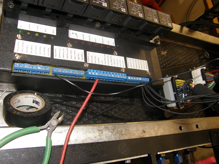
Today we will set up as described in the first point above.  Right behind the dyno stand is a tray where you can put electronics stuff.  In the shot below,
 you can see two boxes, a relay box that I designed and built myself, and the MS3-Pro EFI box. 


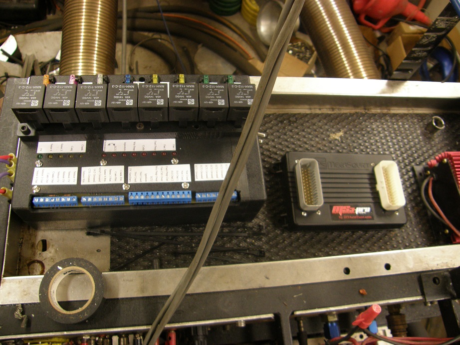
(By the way, those thick gray wires in the front go up to the air turbines and air temperature sensor used by the dyno,
 and are not related to the EFI system.)

I designed the relay box so it can be used for most of the functions in a race car or street rod, so it is a little
bit of overkill on the dyno.  It contains 8 30 amp relays, each one fused, a couple of large bypass capacitors to filter
any noise in the vehicle before the power wires to the EFI box, plus a small circuit board with some simple
 circuits used to power LED indicator lights.  Since most of the functions of the car can be controlled with the EFI
system, many of the wires going into the relay box come from the EFI box.  Here's another picture of the relay box,
from the top showing the labels on the screw-terminal connections:


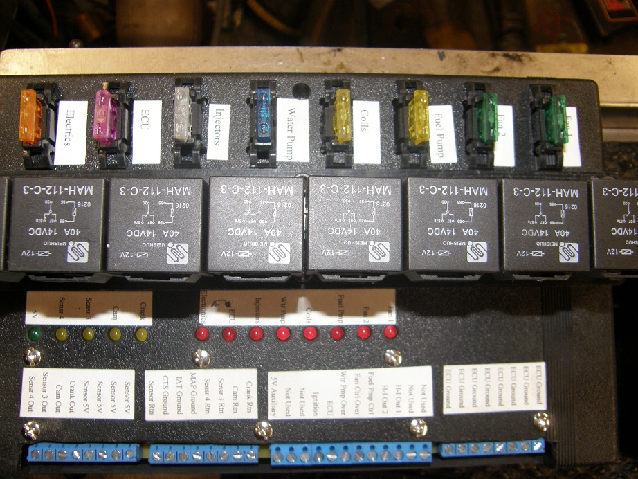
Not all of these terminals will be used for every system, but I wanted to make this box as universal as possible. 
This was the first one I built, and after building it I decided to make a few changes, so I made an updated
version and installed it in my race car last year.  It worked beautifully during Drag Week, giving me no trouble
at all, but there was one feature that I found would make it more useful, and that is having the LEDs on a panel,
rather than directly on the box, because then they could be mounted where they could be more easily seen.  I plan
to make another revision of the box that adds that feature, and make it available for sale at some point.

In any case, don't get thrown by the presence of the relay box; it is not required for the EFI installation, because
stand-alone relays can be used instead.

On the side of the box are two terminal strips, as shown in the photo below.  These are the main, high current
input and output terminals of the relay box, where power comes in and goes out.  The top terminal strip is for the
input power.  I already have the input power wires hooked up in the photo.  The two wires on the left are the power
and ground wires that are dedicated to the EFI system.  This is important:  to minimize electrical noise, always
run separate, #10 or #12 power and ground wires directly from the battery.  In my case I'm running them to the
relay box, and then from the relay box to the EFI box, but that won't matter because the EFI box is right next door.
Without the relay box, you would just run the wires to a 30 amp relay.  Also, it is a very good idea to put a
capacitor across the power and ground wires to the EFI box, to make sure that the EFI box gets a stable, clean
voltage supply.  I have a large capacitor just for this purpose built into the relay box, but if you are not using
the relay box you can also use one of the MSD filter capacitors, MSD part number 8830.

The other two power wires coming in to the top terminal strip are for the non-EFI functions in the relay box, like
the electric fans, electric fuel pump, electric water pump, etc. etc.  These wires can also be run directly from
the battery, but its not as critical.  There is room for two additional 12V wires, not just the one I have connected,
in case you need two wires to handle all the current going through the relays.  In the photo, you can't see the
labels for the top terminal strip, but they are all marked.


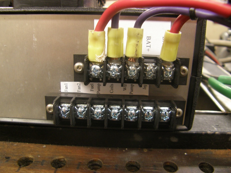
The bottom terminal strip shows all the outputs from the relay box.  These are all 12V 30 amp outputs that run through
the fuses and relays mounted on the box.  On the dyno the only ones we will be using are the output for the electric
water pump and the electric fuel pump, but obviously in the car all of the outputs could be used. 

Next, below there is a photo of the MS3-Pro with the two large wiring harness cables plugged in:


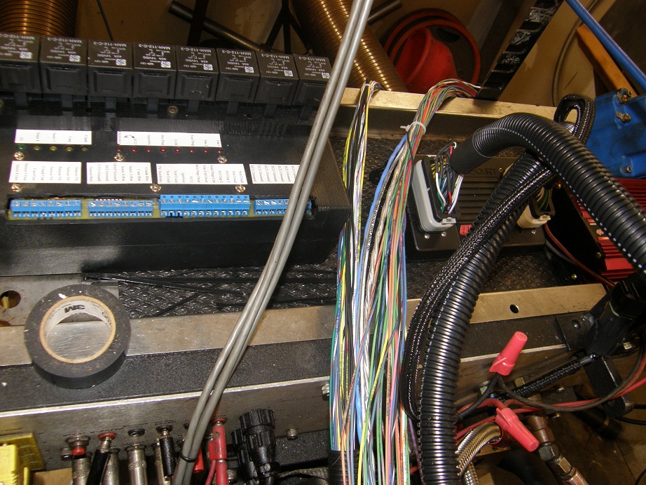
Yep, lots of wires LOL!  Don't panic though, depending on the system, probably 1/2 to 3/4 of them won't even be used. 
They are there to allow all of the options of the EFI system to be used.  Different ignition strategies use different wires,
and the MS3-Pro is set up to work with almost any conceivable engine combination, so the wires for each have to be
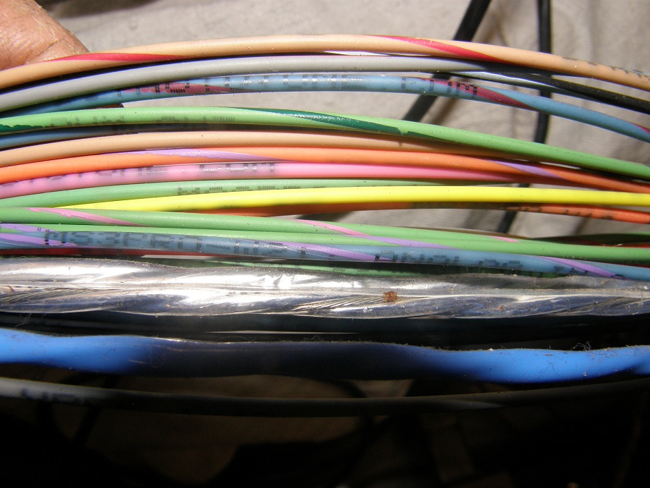
available.  Telling the wires apart is easy, because each one is color coded, and also labeled in print with its
purpose.  I find myself having to take my glasses off to read some of the print, but despite that it is not too
difficult to tell the wires apart.  See the close-up of one bundle of wires below:


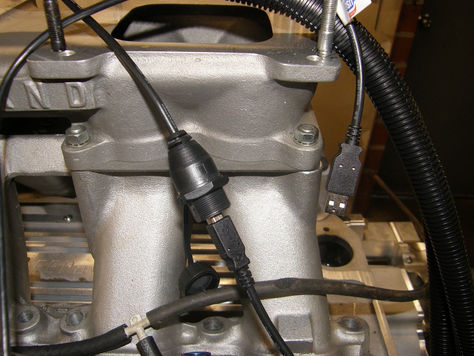
So, now we'll get started hooking everything up.  First, we have to have a way to communicate with the EFI box from
a computer.  The easiest way is via the USB port.  Notice that there are two connectors on the MS3-Pro, one white
and one gray.  The USB port is in the cable from the gray connector.  It has an end that allows for a panel mount,
and the USB cable you need also comes with the MS3-Pro.  Here's a picture of the USB port with the cable plugged
into it:


The other option for connecting up to the EFI box from the computer is the older RS232 method; here's a picture of
that connector, which is found in the wiring bundle from the white connector on the MS3-Pro:


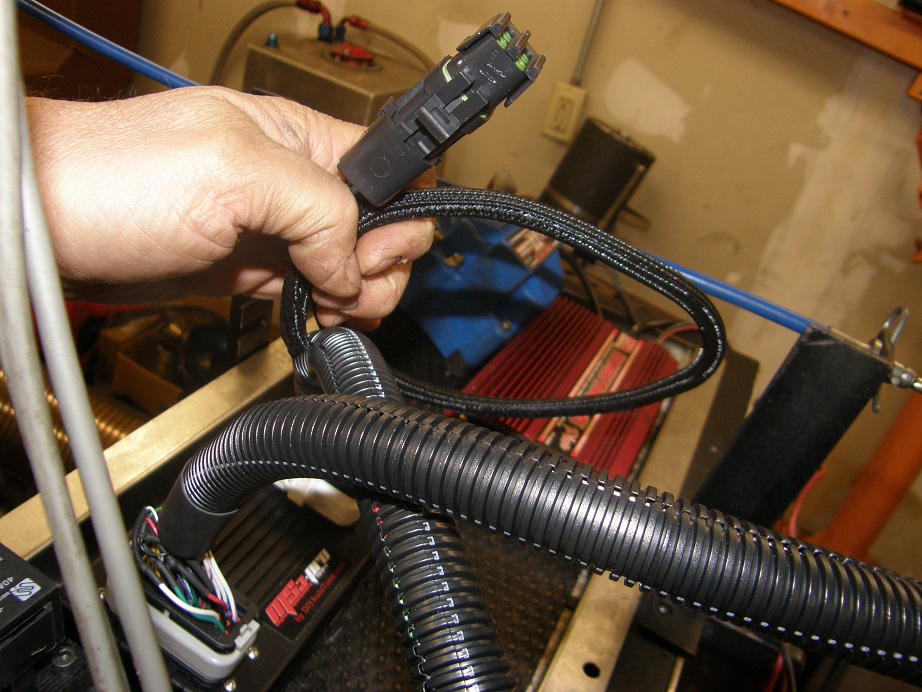
Plugging the USB cable in is easier, so we won't be using the RS232 connector.  I just hung it out of the way, over
the back of the dyno shelf.

Now we'll get started hooking up the necessary wires.  Here's a picture from the MS3-Pro manual, showing the basic
power, ground, and fuel wiring of the EFI system:


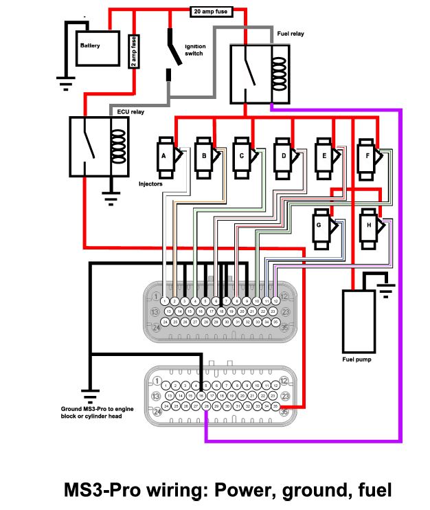
Looking at this wiring diagram, you can see that some of the parts are not part of the MS3-Pro, the car battery and
ignition switch for example.  But you do need two fuses and a couple relays; I've found that automotive style 30
amp relays, available at any auto parts store, work fine.  The two relays and the two fuses are built into my relay
box, but if you haven't got that you have to source the parts from NAPA or some other auto parts place.  There's
nothing complicated here, the ignition switch just energizes the relays when you turn it on.  One of the relays is
marked ECU, and that is just another name for the MS3-Pro box.  Notice that the while the relay that energizes the
MS3-Pro turns on immediately with the ignition switch, the relay that controls the fuel pump doesn't; it is controlled
by the purple wire from the white connector.  The reason for this is that on power-up the MS3-Pro cycles through
the fuel injectors and the ignition system to make sure it is working, and if the fuel pump was on you'd be shooting
fuel out of the injectors, and potentially causing a backfire.  So, the MS3-Pro doesn't connect that purple wire to
ground (allowing the fuel pump relay to turn on) until that power-up system check is complete.

Now let's look at the other important wiring diagram, for the sensors:


Again, not everything shown here is going to be required for every engine.  You do need a minimum of five sensors to
run the EFI system.  First is the crank sensor.  This can be the electronic pickup in a Ford or MSD electronic
distributor, or some other type of pickup in an electronic distributor, or a crank trigger, or a 36 or 60 toothed
wheel with an external sensor.  Something has to provide the tach signal to the MS3-Pro, so that it knows the engine
is turning, and how fast. 

Next, you need a MAP (Manifold Absolute Pressure) sensor, which is basically a vacuum sensor connected to the intake,
under the throttle plates.  You need a throttle position sensor, so the MS3-Pro knows how far the throttle is open.
Finally, you need a coolant temperature sensor and an air temperature sensor, because tuning the engine requires
knowing how hot the incoming air is, and what the engine temperature is. 

Outside of these five sensors, an oxygen sensor is also a really good idea.  The oxygen sensor tells you what your
air/fuel ratio is, and you can use that information to tune the engine.  It can also be used in a feedback loop, so
that if you want your engine to be constantly running at, for example, an air/fuel rato of 13:1, you can put 13 in the
software in something called the Target A/F table, and the MS3-Pro will constantly adjust the fuel going to the
injectors to keep the oxygen sensor reading 13:1.  Now, here's the problem with an oxygen sensor:  they need to be
regularly re-calibrated, and they can wear out.  I'm referring here specifically to wide-band oxygen sensors, which
can read A/F mixtures between 9:1 and 16:1.  Narrow band oxygen sensors are used on production cars, and only read right
around 14.7:1 (which is the ideal mixture), and seem to last forever.  In my experience, though, the wide-band oxygen
sensors don't last that long and are often inaccurate, unless regularly calibrated.  So, my preference with EFI systems
is to use the oxygen sensor to fill in fuel table in the software, and then run the engine in open loop, not in the
feedback loop or "closed loop" mode.  That way, if your oxygen sensor goes bad, it won't matter, because the engine
is getting its instructions from the fuel table.

If you want to run fully sequential fuel injection, you will also need a cam sensor.  You can run batch fire (all 8
injectors opening to release fuel at once, during every other revolution), or bank fire (4 injectors one one cylinder bank
opening at once, then waiting 360 degrees, and the four injectors on the other bank opening), with only the crank
sensor.  But if you want full sequential fuel injection, where each injector squirt is timed to each cylinder, you
need a cam sensor so that the MS3-Pro knows when each cylinder is at TDC on the firing stroke.  A cam sensor can be
built into the engine in a variety of ways, for example as shown previously in this thread, through the timing cover
inspection plate.  You can also use a Ford distributor as a cam sensor, by knocking off 7 of the 8 teeth on the
reluctor, and then using a crank trigger setup or a 36 tooth wheel with a crank sensor.  The single tooth left on the
Ford distributor will give you one output pulse for every other crankshaft revolution.

The MS3-Pro diagram above also shows knock sensors, which are available on some engines, but we won't cover those
here; for the purposes of this build we will ignore the knock sensors.

One last thing to note before we leave this wiring diagram, and that is the ground connection for all the sensors. 
Note that all the grounds are connected together, to a wire called Sensor Return.  This is important for an accurate
result from all the sensors, and has to do with making sure that all the sensor outputs are referenced to a common
ground voltage. 

So, let's start wiring this all up.  In the MS3-Pro instructions there are two tables describing the purpose of all
the wires from the connectors.  I have reprinted the tables below:


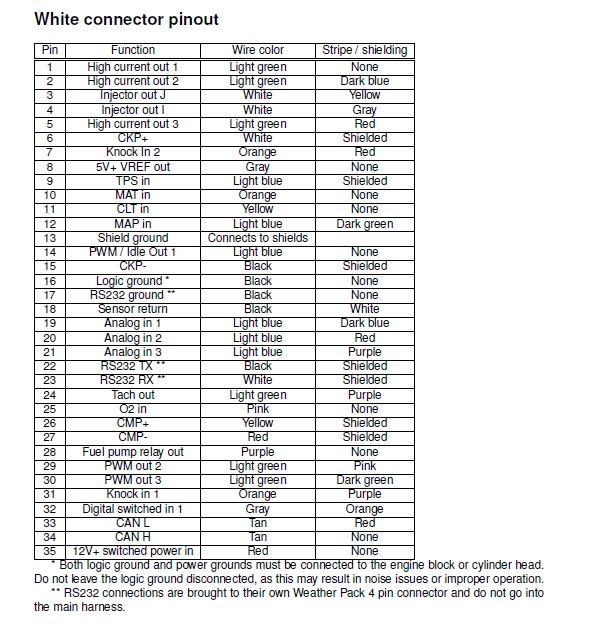
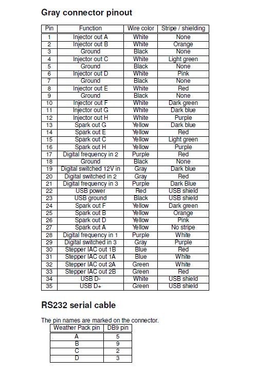
All we have to do is go down the list for each connector, decide if we need to use each wire, and hook it up if we
do.  Before you start, disconnect the battery so that you don't inadvertently short something out with battery power.

We'll start with an easy one, which are the ECU grounds.  These are pins that need to be tied together to the negative
wire coming from the battery, that powers the MS3-Pro.  They are all black, with no stripes. There is one wire from
the white connector (pin 16), and five from the gray connector (pins 3, 5, 7, 9, and 18).  Hook these all together, and
connect them to the negative wire from the battery.  On my relay box I have a separate terminal strip for them, with
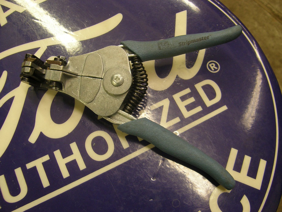
8 stations, labeled ECU Grounds.  Shorten and strip the wires as necessary, and make the connections. By the way, when
you are stripping wires, it pays to have one of these automatic strippers, which are about $18 at my local building
supply store:


Also in the white connector bundle you will find a black wire with a white stripe; this is the sensor return wire,
pin 18 on the connector.  Pull that one out of the bundle and set it aside, because you will need it when you hook
up all the sensors.  On my relay box I have a separate line of screw terminals for all the sensor grounds, so I
stripped mine and hooked it into that line of terminals.

Now let's run the ignition wire.  Remember that the ignition wire has to have 12V both in the run AND in the start
positions.  If you don't have power in the start position, the fuel pump will shut off and the MS3-Pro will power
down, and the engine won't start.  Make sure you confirm this with a test light after you have made this connection. 
If you are sourcing your own relays, the ignition wire goes to one side of the coil of both relays.  On the dyno I
have an ignition switch on the console, and a dedicated screw terminal for that on my relay box, so I just ran a wire
from the switch to the box.  Here's a picture of the relay box as it stands at this point, with the six ECU grounds,
the sensor return wire, and the ignition wire connected:


After you connect the ignition wire to the relay, you have to connect the switched 12V wire on the MS3-Pro (pin 35,
red wire) to the ECU relay, as shown in the wiring diagram.  The other side of the relay should go to the 12V wire
you installed from the battery, through the 2 amp fuse.  On my relay box the fuse and relay are internal, so I just
connect the wire from the MS3-Pro to one of the screw terminals.

Let's keep going with wires from the white connector.  Next up is the fuel pump control wire, purple from pin 28. 
This goes to the fuel pump relay coil, as shown in the wiring diagram.  Again in my relay box this is all internal,
so I just attach the purple wire to the screw terminal on the box labeled Fuel Pump Control. 

Now find the gray wire, labeled 5V VREF, from pin 8 and pull it out of the bundle.  You will need that one when we
hook up the sensors.  Again, I have the connections to the sensors internally in my relay box, so I will attach it
to the appropriate screw terminal.

To control the electric water pump, we will use one of the MS3-Pro's programmable outputs.  I selected the one called
High Current Output 2.  What this output does is act like a switch, that can sink up to 5 amps of current.  It is
normally open, meaning the switch isn't flipped.  Under a certain set of conditions, though, that you program in
the software, the switch closes, allowing current to flow.  If we had an electric water pump, or an electric fan,
that required 5 amps or less of current, we could run it directly from this output.  We would simply attach a constant
12V supply to one side of the pump or fan, and then wire the other side to the output.  When the conditions that we
programmed are met, the switch flips or closes, and the pump or fan turns on.  I will go through the programming in
detail later, but for this particular output I programmed it to turn on after the engine reaches 500 RPM.  So, if you
have the key on to check something in the EFI system with the laptop, or even while
the engine is cranking at 100 RPM or so, the electric water pump stays off, to minimize drain on the battery.  As
soon as the engine fires and exceeds 500 RPM, the electric water pump turns on.  You can also wire in an override
switch on this circuit, so that if you want to sit with the engine off but the water pump turning, to cool the engine
down, you can do that too.

Electric water pumps and fans will normally take more than 5 amps, so its a good idea to use the programmable outputs
to energize the coil of a relay, and run the current from the water pump or fans through the high current relay contacts. 
In case you don't know how a relay works, any internet search ought to bring up all the info you need.

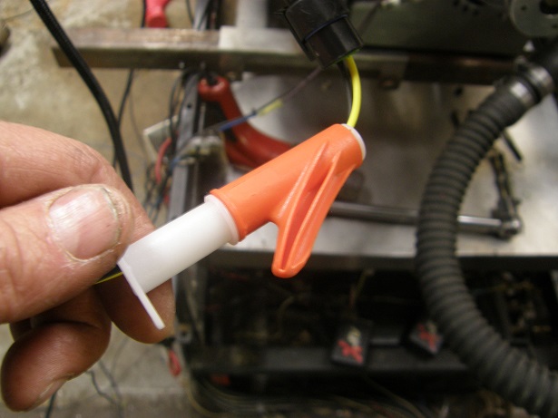
Now let's hook up some of the sensors.  Since we will still be running with carbs to start with, we won't need the throttle
position sensor, but we may as well hook up the coolant temperature sensor (CTS), inlet air temperature sensor (IAT or MAT),
and the manifold pressure sensor.  For both the CTS and IAT sensors, these are two wire devices.  Here's a picture of the IAT
sensor, complete with the pigtail connector with the two wires:


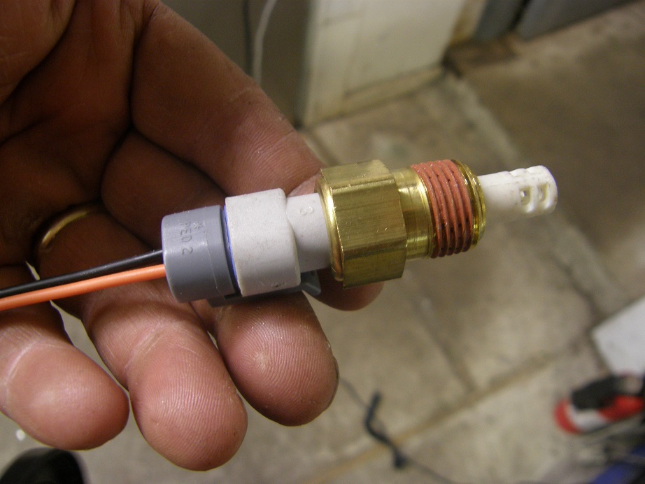
The black wire goes to ground, at the sensor return wire that we pulled out earlier.  The other sensor grounds also go to sensor
return wire, so that wire will have several other wires attached to it when we are finished.  The orange wire is a signal wire, and
goes to the orange wire in the white connector bundle from the MS3-Pro (wire #10, labeled MAT).  Notice that the end of the
IAT sensor is open to expose the sensor element.  This sensor must be installed where it is not subject to water or fuel, like
in the air cleaner.  I like this style of IAT sensor because they respond quickly.  There is another style, though, with a
closed off end, that can be installed in a vacuum port on the intake manifold.  They don't respond as fast, but they still work
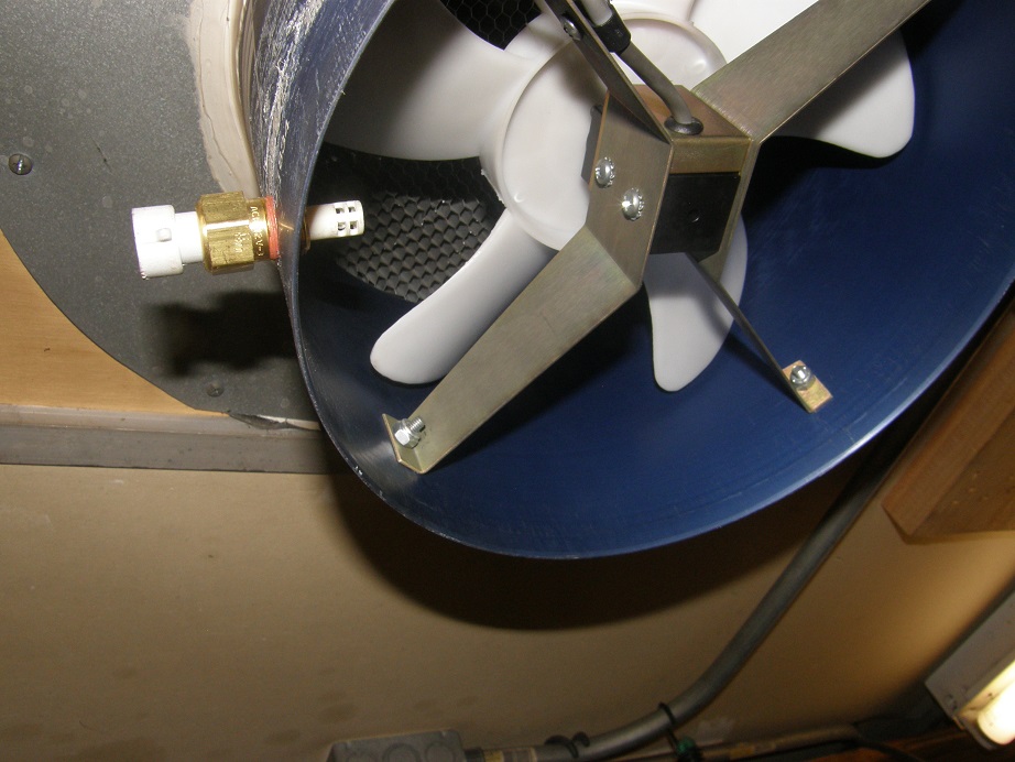
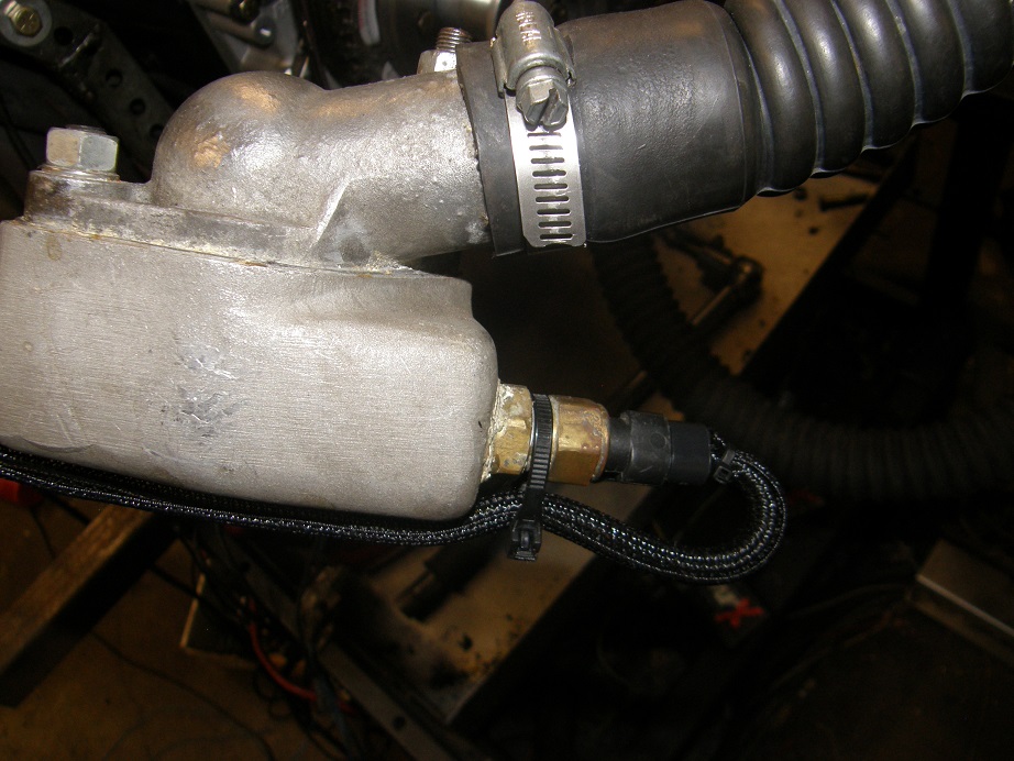
fine.  So, choose the sensor style based on where you want to install it.  Since my installation is on the dyno, I put it up
in the dyno turbine housing that feeds air to the engine:


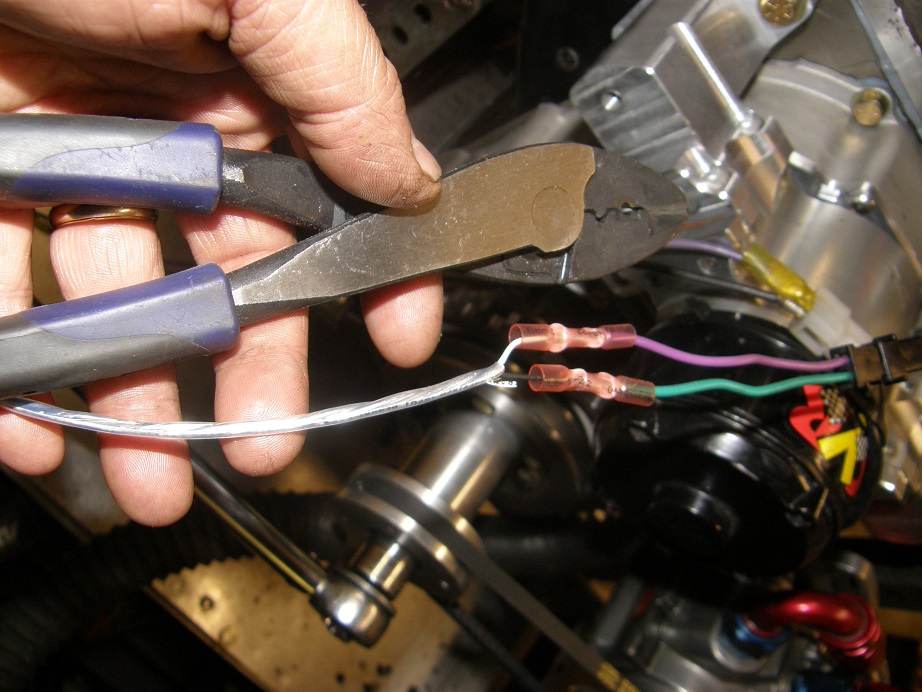
The coolant temperature sensor (CTS) looks just like the IAT, except they all have a closed end because they are exposed to the
coolant in the engine.  The wires coming off the connector on this one are yellow and black.  Again the black wire connects
to sensor return, and the yellow wire connects to the yellow wire (#11) from the MS3-Pro white connector.  I installed the sensor
in the remote thermostat housing I'm using on the dyno:


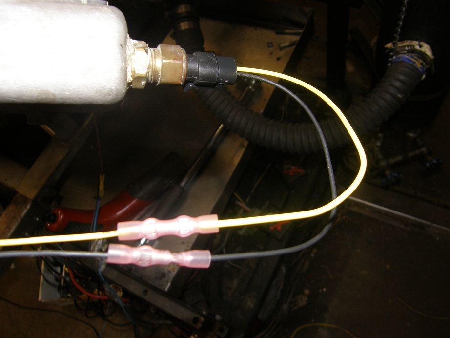
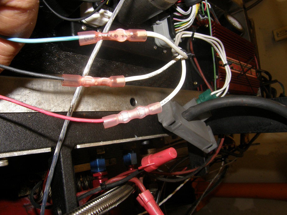
Notice that I'm using crimp style connectors on these wires.  I used to be a solder and heat shrink guy, but that is a whole
bunch of work compared to the crimp connectors.  Further, I have been told of cases where vibration will cause the end of a
solder joint to break the wire, leading to various electrical problems.  For the last couple of years I've been using these
crimp connectors, that come with heat shrink tubing over them, and have not had any issues.  The previous photo was before
heat shrink; here's what the connections look like after heat shrink:


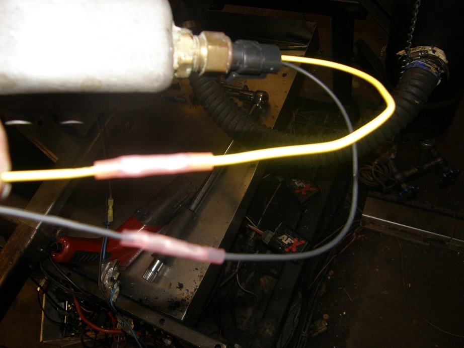
Sorry for the poor photo quality, but you get the idea.  The heat shrink tube seals the end of the connectors to keep water out,
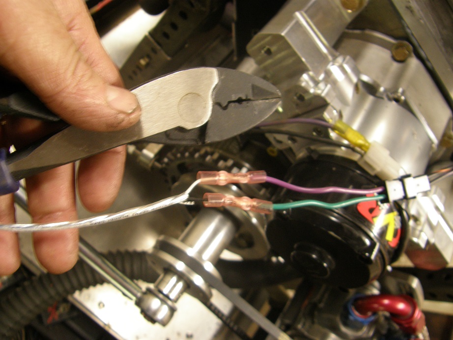
plus it holds the wires rigidly in place so vibration won't bend them back and forth at the joint.  Just make sure you have a
good crimping tool to really put a crimp on those connectors; here's the one I use:


It's pretty heavy duty, and I squeeze the heck out of it when I crimp the wires.  I think it cost about $20 at the local building
supply store (Menards), which is also where I buy the crimp connectors.

Since the CTS sensor is going to be out there where you can see it in the engine compartment, we want the wiring to it to look
nice.  So, I usually cover it with a heat and abrasion resistant covering.  This stuff is sold as Powerbraid by Painless Wiring,
but it turns out you can buy it a lot cheaper at McMaster Carr.  It's on this page, and is called Wrap-Around Sleeving:

https://www.mcmaster.com/#catalog/123/857/=17xa1dj

This stuff just curls around the wire and makes a nice, clean installation, not like that plastic stuff that you see so much. 
It can be hard to install, though, and Painless makes a nice set of installation tools to make this part much easier. See the
link below:

https://www.summitracing.com/parts/prf-70941/overview/

Here's one of them installed on the CTS sensor wires.  The plastic installation tool is in two pieces and rotates around so that
a slot is open to install the wires.  Then, you rotate it closed, feed the wrap over the little nub on the tool, and it slides on
right over the wires.  Here's a couple of pictures:


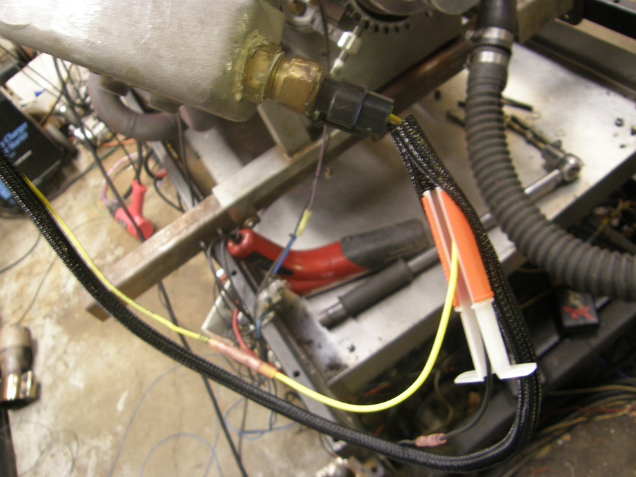
Using this tool you just slide it along the wire, and the wrap goes on without any trouble.  You can tie wrap or heat shring
the end of the wrap at the connector to make a nice, neat installation:


Next let's do the MAP sensor. This sensor has three wires; it needs a 5V power supply from the MS3-Pro.  This is the gray wire
marked 5V VREF that you pulled out of the bundle earlier.  Here's a picture of the sensor with the wires hooked up; the sensor
is the small gray box in the background with the vacuum hose attached to it:


Obviously you plug the vacuum line into a manifold vacuum source.  In the picture the black wire goes to sensor return, and the
blue wire with the dark green stripe goes to pin #12 on the white connector.  The red wire in this photo goes to my relay box,
but if you were hooking up without that it would go to the 5V VREF wire.  This is a GM MAP sensor, and the wiring is shown in
the picture below:


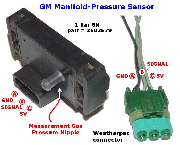
Notice that this sensor is a 1 Bar sensor.  One bar is equal to one atmosphere, which means that this sensor is good for naturally
aspirated applications.  If you are using a supercharger or turbos, and you want to run up to 14.7 psi of boost, you need a two bar
sensor.  Three, four, and five bar MAP sensors are also available, to handle higher boost levels.  Choose the sensor that is
closest to your expected range of operation.

Also, for moving between manifold pressure units, the following conversions may be helpful:

Standard atmospheric pressure = 29.92" of mercury = 14.7 psi = 100 kPa

The EFI units typically use kPa in their fuel and timing tables, which is convenient because of how close the kPa atmospheric
number is to 100. 

One other thing to remember is that people tend to think of manifold pressure as vacuum, i.e. you have 10" of vacuum at idle.
Remember that when we are walking around we are all under atmospheric pressure.  So, as I sit here I'm under about 29.92 inches
of mercury pressure, or 14.7 psi of pressure, or 100 kPa of pressure.  A vacuum condition in the manifold means that
there is less pressure in the manifold than atmospheric pressure.  So, 10" of vacuum is the same as 19.92" of mercury for
pressure (29.92" - 10"), or about 9.8 psi, or about 66 kPa. When tuning the engine the fuel and ignition tables will make sense
if you think of manifold pressure, rather than vacuum.

As a first step in converting this engine to EFI we are going to retain the distributor, but have the timing controlled by the
EFI system.  So, I pulled the distributor on the engine and replaced it with a locked MSD distributor, no mechanical advance.  Next
I hooked up the MSD distributor pickup to the CKP+ and CKP- wires from the white connector on the MS3-Pro, pins 6 and 15.  These
wires come together in a shielded cable.  The white wire is CKP+.  It is important that these are hooked up correctly to the two
wires coming from the MSD pickup.  MSD says that the black wire with the orange stripe from the distributor pickup is +, and the
black wire with the purple stripe is -.  I don't know why, but the MSD extension wire that plugs into the distributor pickup
connector has different color coding, solid purple wire for + and solid green wire for -.  Go figure.  Anyway, the white wire
from the MS3-Pro should go to the solid purple wire on the connector, or the black wire with the orange stripe if you choose to
cut the connector off and wire it up directly.  Here's a picture of the wiring to the distributor, also showing my crimp tool
again:


To make sure the engine start, turn the engine to the maximum advance point, say 35 degrees BTDC.  Then adjust the distributor
so that at the maximum advance one of the tangs on the reluctor wheel is pointed straight at the pickup, and then make sure that
the rotor is pointing toward the #1 plug wire.  You can then tighten the distributor; further timing adjustments will be made
in the software.

The last sensor we will hook up will be the O2 sensor.  I used an LC-1 wideband sensor and control unit from Innovate Motorsports
on this engine.  I've had this setup for a while, and now the LC-1 has been replaced by the LC-2; I assume the hookup is about
the same.  You just have to follow the instructions with the unit, and hook the wideband output wire (brown wire on the LC-1) to
the pink wire, pin 25 on the white connector.  Also, the wideband O2 sensors are heated, and there is a fair amount of electrical
current running through them as a result.  So, rather than ground the LC-1 to the sensor return wire, I grounded all the wires
that require a ground connection to the ECU power inputs at the relay. 

We have one more wire to connect, and that is the tach out wire.  Normally this wire would hook to your vehicles tachometer, or
any other place where you need a tach signal.  However, when running an MSD ignition, this wire is the trigger wire, so it is
connected to the white points input wire on the MSD.  Once that wire is connected, the MSD distributor will feed into the MS3-Pro,
and the MS3-Pro will trigger the MSD to create the spark.

This pretty much completes the wiring required for this type of ignition setup.  The remaining wires are not used, and can be cut
off and moved out of the way.  I would recommend leaving about 12"of wire from each connector, and taping all the ends up so that
they don't short to each other somehow.  Then you could still connect to them if you change your ignition setup later.  In my
case I will be using these wires later as I move from one ignition setup to the next, so I will just tie them up out of the way
on the back of the dyno stand.

Next we will power up the ignition, start up the software package, connect to the MS3-Pro and configure it to work with the wiring
we have installed.

First, you need to install Tuner Studio and Megalog Viewer on your laptop.  These are available at this link:

http://www.tunerstudio.com/

There are free versions of both these programs, but you can also buy them together for about $90 to get all the features.  I've
done that, so the screen shots you will be seeing below are from those versions.  You will also need the most recent version of
Java installed on your laptop; most people have this already.

After installing the software, connect your USB cable between the MS3-Pro and your laptop, and open up Tuner Studio.  (FYI, some
virus checkers will really slow this software down when opening it up; I have a virus checker called ESET and it will take up to
10 minutes to open a project in Tuner Studio if it is active, so I temporarily disable it when running Tuner Studio).  Click on
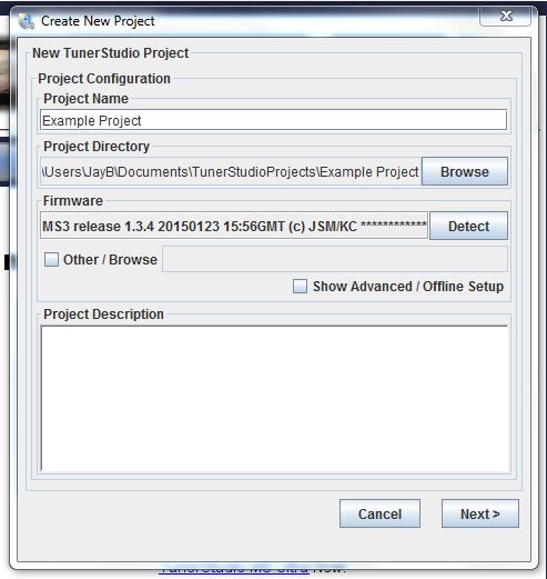
Create New Project.  A screen comes up for you to enter the project name and the directory where the project data will be stored. 
I usually use the default directory.  Then, there is a box called Firmware where you need to detect the MS3-Pro.  Click the little
Detect button next to the box.  The Tuner Studio software will try to connect to the MS3-Pro through the USB cable.  It will
probably find two connections, one via the USB port and one via the RS-232 port, as shown below: 


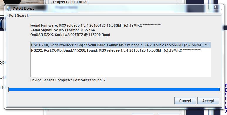
Make sure the one with the USB port is enabled
and click Accept.  You will then be back at the previous screen, as shown below.  Click next.


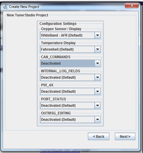
Next is a screen to set up some of the key functions in the software.  The first two items are probably the one ones you need to
worry about, using a Wideband oxygen sensor, and Fahrenheit for the temperature scale.  You can deactivate all the other
functions, as shown in the screen below.  When finished, click Next.


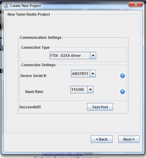
The next screen is mostly filled in for you, and all you are looking for is to see if the computer port you are using will work. 
Click Test Port; if it says Successful, you are in good shape.  If not, you may have to work on getting the USB ports set up
properly in the Device Manager of your computer.


Assuming you have a successful connection, Tuner Studio will now ask you to select a dashboard.  There are a bunch of different
ones you can preview and pick from, but I usually just go with the default at this point, since you can modify the dashboard any
way you want later.  Here's a picture of the default dashboard, which comes up as soon as you click the Finish button in this
screen:


Now its time to configure the software so that the engine will run.  There are dozens of menus that allow use of all the options
that the MS3-Pro is capable of, but we only need to concern outselves with a few.  As an overview of the menus, I made this brief
video, link below.  I took this with my camera pointed at the computer screen, so its a little fuzzy, but I'm sure you'll get the
idea:

https://youtu.be/PpGirKgaMXU

So, we'll get started by pulling down the Basic/Load Settings menu and opening up the Engine/Sequential settings.  A picture of
this menu is below:


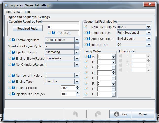
Everything on the left side of the menu relates to fuel, so we won't be using it yet, but we might as well
configure it now.  First thing is to click on the Required Fuel button.  This calculates a typical pulse width for your fuel
injectors; in other words, how long they stay open. You will need to input the size of the engine in cubic inches, the number
of cylinders, the flow rate of your injectors, and the perfect A/F ratio (14.7).  Here's what mine looked like:


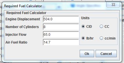
Click OK and the required fuel value will appear in the menu, along with the engine size and injector size in cc.  You can leave
the rest of the parameters as-is for now, but we will be using the Speed Density approach to control the engine, which I believe
is the default filled in to the menu.

On the right side of the screen, modify it to turn sequential EFI off for now (since we are starting with carbs), and also turn
off the injector trim (which allows different injectors to inject different amounts of fuel, to fine tune the engine).  Also, you
have to fill in the engine's firing order.  The Engine and Sequential Settings box should look something like this when you are
done:


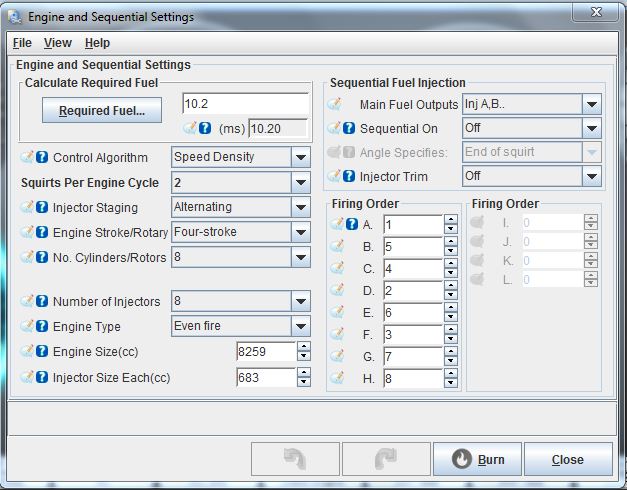
After making all the changes, click Burn; this saves the changes to the program in the MS3-Pro.

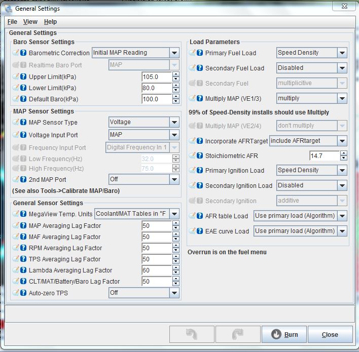
Next lets open General Settings under the Basic/Load settings tab.  Here we are going to set up the MAP sensor.  Just change the
values in the menu to match those in the picture below:


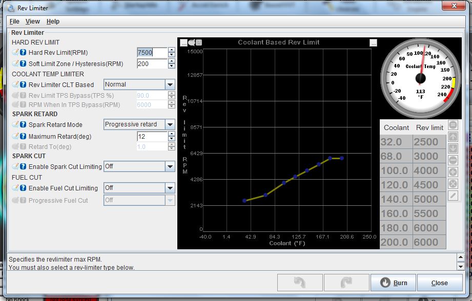
Click Burn, and close.  Next go to the Rev Limiter menu, and set the rev limit where you need to be with your engine.  The soft
limit zone comes in the specified RPM below the hard rev limit, to slow the engine down a bit before it hits the hard rev limit. 
The Coolant Temp Limiter will adjust the rev limit based on engine coolant temperature, for example to keep the engine from
revving way up when it is cold.  If you select Normal here, it is disabled, but if you choose to enable it, you can then adjust
the graph points on the right.  The rev limiter works by removing engine timing, and the progressive retard does this
progressively.  Imagine that.  You can also specify a spark cut-off or fuel cut-off to enforce the rev limit.  I set mine up as
shown in the picture below:


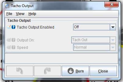
Click Burn, and close this window.  The last screen under this menu that we will address is the Tacho Output screen.  Normally this
output is used to drive your tachometer or other device that needs a digital tach input.  However, since we are setting the
engine up to run off the MSD, we will use the Tacho Output to drive the white points wire on the MSD.  So, we have to tie it to
the ignition table.  In order to do this, we have to disable it here, as shown in the screen below:


Burn and close this window.  Now we will set up the ignition triggering.  Under the Ignition Settings tab, click on Ignition
Options/Wheel Decoder.  You will get this window:


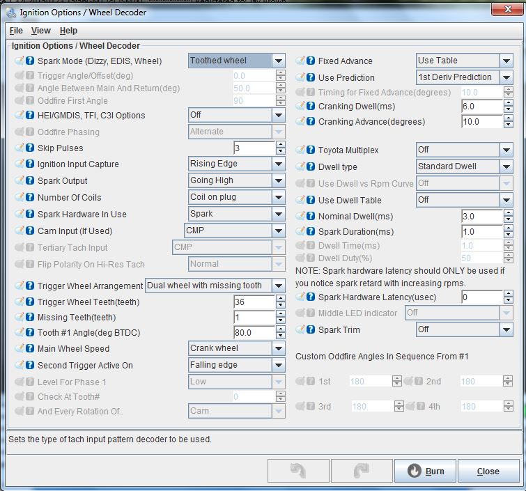
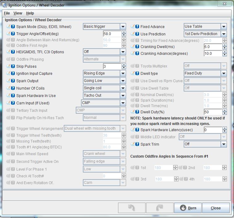
To make this work with the MSD distributor we have to set the spark mode as a Basic Trigger, with capture on the rising edge,
spark output going high, and specify a single coil.  For the Spark Hardware in Use box, we have to change this to Tacho Out; this
makes the Tacho out wire obey the timing setup in the timing table.  One other thing to note here is the Trigger Angle/Offset
box.  This is where you can adjust the base timing in the computer, rather than by twisting the distributor.  When finished the
Ignition Options screen should look like this, when configured for an MSD distributor:


Edit 6/6/17:  Note that the diagram above has been updated, there was one parameter that was incorrect when I captured the screen
the first time.  Spark Output should be Going Low, not Going High.  Also note that the Trigger Angle shown above is what I ended up
with, not what I started with.  I believe I started with 10 degrees for a trigger angle.  See my next instructional post for setting that up.

Now, under the same tab, open up the Ignition Table.  It will look something like this:


The gray boxes on the left side of the table (Y axis) show the manifold pressure, from the MAP sensor.  These can easily be changed
for customization purposes.  When I first opened this table it was set up for a 4 bar MAP sensor, so it went all the way up to
400 kPa.  You can just click on each box and fill in whatever number you want; for a naturally aspirated engine, a range of 30
to 105 kPa, in 5 kPa increments, is sufficient.  This is equivalent to about 20 inches of vacuum to zero inches.  The gray boxes
on the bottom side of the table (X axis) show RPM values. All the numbers in the table show ignition advance.  So, for example at
5000 RPM and 100 kPa (zero vacuum), timing is 35 degrees BTDC.  This would correspond to an engine with wide open throttle at
5000 RPM.  Another example, at 800 RPM regardless of manifold pressure, timing is 20 degrees BTDC.  Tuning the engine involves
driving the vehicle and adjusting these values for best performance.

To change the numbers in any of the boxes, you can just click on the box and type in a new number.  Or, you can highlight a string
of boxes, then click the = sign at the top of the map, and type in your number, and all the boxes that were highlighted will get
that number.  You can also select boxes and add, subtract, or multiply the numbers in them using the operators at the top of the
table.

Sometimes it may be easier to see what the timing table looks like if it is presented in graphical form.  Click the 3D View box
at the top of the timing table and you will see this:


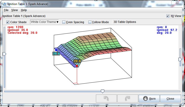
This view can make it easier to see major discontinuities in the table, and point you to the cells that may need to be modified.
Generally, a smoother table is better.

When you get done setting up the timing as best you can at this point, click Burn and close the table.  Sometimes when you make
these changes you will get this message across the dash:


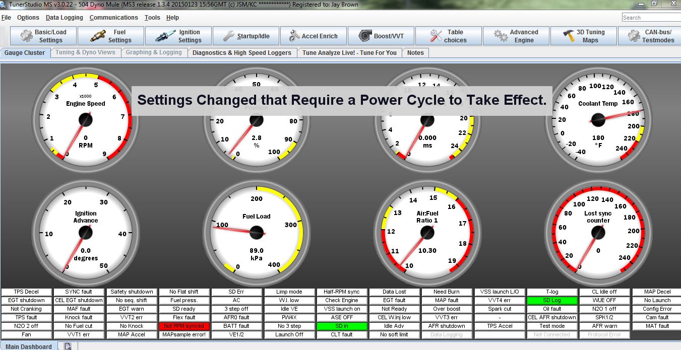
When you see this, just flip the ignition off for 3 seconds or so, then turn it back on.  The MS3-Pro needs the power cycle to
store the new data.

Under the fuel settings tab, you can also look at the fuel table, or VE Table.  Since we are not fueling with the EFI setup yet,
you don't need to do anything to it at this point.  But you will notice it has the same axes as the timing table.  Probably a
good idea to set the manifold pressure and RPM levels the same as you set them in the timing table.  Notice that this table came
in with up to 400 kPa (4 Bar) on the left side.  Just change those numbers, and the RPM numbers, to match the other table.


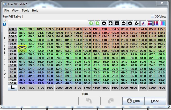
The numbers in the VE table represent Volumetric Efficiency, hence the name VE table.  In practical terms, when you increase a
VE number in the table, you are adding fuel to the engine. We won't mess with this table again until we are actually injecting
fuel with the MS3-Pro.

Now let's set up the O2 sensor.  To do this we need to go to the Tools menu up at the top of the board.  Tuner Studio keeps these
calibrations locked, so that an errant keystroke won't result in a significant calibration change on the engine.  Under Tools,
go to Unlock Calibrations, select Unlock from the drop-down box, then burn and close.  Now, again from the Tools menu, select
Calibrate AFR Table.  From the drop-down menu, select your wideband O2 controller.  I am using the Innovate Motorsports LC-1, as
shown in the picture:


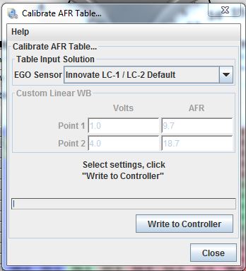
When you have selected your wideband O2 controller from the list, click Write to Controller, then close the window.  Then,
re-lock the calibrations so they don't change.

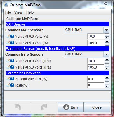
Also under tools, you can click Calibrate MAP/Baro, to set up for the correct MAP sensor.  Since I am using the GM 1 Bar sensor,
that is what I selected:


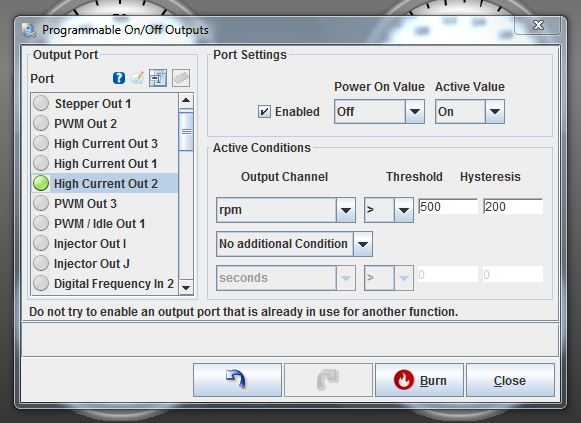
The last thing we are going to do before starting the engine is configure the High Current 2 output, that I am using to control
the electric water pump.  Under the Advanced Engine tab, click on Programmable On/Off Outputs.  On the left side of this menu
is the output port.  Scroll down the list until you find the output that you want to program, in this case High Current Out 2.
On the right side, click Enabled, and make the Power On value OFF, and the Active Value ON.  This means that when the ignition key
is on, the output is off, but will turn on when it is active.  On the lower right side, you can define active conditions.  For the
water pump, I have selected RPM for the output channel, then a "greater than" sign, then 500 RPM for the threshold, and 200 RPM
for hysteresis.  The way this is configured now, the electric water pump will not turn on until the engine speed reaches 500
RPM.  It will stay on until the engine speed drops below 300 RPM, due to the 200 RPM hysteresis value.  Here's a shot of the
screen:


Notice we have not used any additional conditions.  They are available; in the drop down box you can specify AND or OR, and then
add additional conditions.  For example, with an electric fan, you can do the same thing that you do with the electric water pump,
to keep it from running while the engine is cranking.  But you can also add a condition so that it also won't run until the
coolant has reached a certain temperature.  This set of parameters might look like this:

RPM > 500, Hysteresis 200

AND

Coolant Temp > 170, Hysteresis 10 degrees

This way, the fans don't come on until the engine is warmed up to temperature, and is running.  And if the temperature drops
below 160, the fans automatically shut off.

Despite setting it up this way, you can also bypass these programmable outputs with a mechanical switch.  To do this you have to
understand that the outputs on the MS3-Pro are typically current sinking outputs.  They are a transistor that acts like a switch,
and connects the output to ground.  So, when we wired the water pump earlier, we put a constant 12V to the water pump relay coil
when the ignition switch was on, and connected the other side of the relay coil to the High Current Out 2 wire.  With the output
turned off, the "switch" is open, so no electric current can flow, and the relay coil is not energized.  As soon as the output
turns on, the "switch" closes, allowing current to flow and energizing the relay coil, which in turn allows voltage to the water
pump. 

Now let's say we've just made a pass at the track and have pulled back into the pits, and want to cool down the engine between
rounds.  If we wire a toggle switch between High Current Out 2 and ground, and flip the switch, current can then flow through the
relay coil to ground, even if the engine is not running.  On my car I have a switch like this on the electric water pump and also
on the fan circuit.  I don't use them very often, but they are there if I need them.  Most of the time the electric water pump
and electric fans operate automatically, and I don't have to think about them.

One last thing, and that is configuring the dash in Tuner Studio.  There are a multitude of different gauge types, gauge styles
and colors and texts available, so you can customize your dash any way you want.  Rather than trying to explain this in words,
I've created this short video to show how it works. 

https://youtu.be/PW1UdM_4KLQ

This is pretty much the whole setup for adding the MS3-Pro into the dyno mule, while still using the MSD distributor for a trigger
and the MSD Digital 6 for spark.  Next time we will go through a few things we need to do to start the engine, and then work on
transitioning to the 36-1 toothed wheel.


« Last Edit: June 06, 2017, 01:17:35 PM by jayb »
Jay Brown
- 1969 Mach 1, Drag Week 2005 Winner NA/BB, 511" FE (10.60s @ 129); Drag Week 2007 Runner-Up PA/BB, 490" Supercharged FE (9.35 @ 151)
- 1964 Ford Galaxie, Drag Week 2009 Winner Modified NA (9.50s @ 143), 585" SOHC
- 1969 Shelby Clone, Drag Week 2015 Winner Modified NA (Average 8.98 @ 149), 585" SOHC


57 lima bean

  • Guest
Re: Dyno Mule to Test 351C Intakes on the Intake Adapter, Carb and EFI
« Reply #37 on: June 05, 2017, 10:10:14 AM »
hys·ter·e·sis
ˌhistəˈrēsis/Submit
nounPHYSICS
the phenomenon in which the value of a physical property lags behind changes in the effect causing it, as for instance when magnetic induction lags behind the magnetizing force. 8)...

jayb

  • Administrator
  • Hero Member
  • *****
  • Posts: 7404
    • View Profile
    • FE Power
Re: Dyno Mule to Test 351C Intakes on the Intake Adapter, Carb and EFI
« Reply #38 on: June 05, 2017, 11:18:41 AM »
Very good, Professor Pearley!  In this case it refers to the difference between the ON point and the OFF point.  If they were both the same, you would get what we in the electronics world call "jitter", which is the signal hunting back and forth between on and off right at the operate point.  Hysteresis prevents that from happening.
Jay Brown
- 1969 Mach 1, Drag Week 2005 Winner NA/BB, 511" FE (10.60s @ 129); Drag Week 2007 Runner-Up PA/BB, 490" Supercharged FE (9.35 @ 151)
- 1964 Ford Galaxie, Drag Week 2009 Winner Modified NA (9.50s @ 143), 585" SOHC
- 1969 Shelby Clone, Drag Week 2015 Winner Modified NA (Average 8.98 @ 149), 585" SOHC


turbohunter

  • Hero Member
  • *****
  • Posts: 2509
    • View Profile
Re: Dyno Mule to Test 351C Intakes on the Intake Adapter, Carb and EFI
« Reply #39 on: June 05, 2017, 11:57:38 AM »
Whew what a read.
I'm taking my third stab at it. Lots to digest. I'll prolly read it three more.
Thanks Jay for putting all this down. I hope you know its appreciated.
Marc
'61 F100 292Y
'66 Mustang Injected 428
'66 Q code Country Squire wagon


machoneman

  • Hero Member
  • *****
  • Posts: 3851
    • View Profile
Re: Dyno Mule to Test 351C Intakes on the Intake Adapter, Carb and EFI
« Reply #40 on: June 05, 2017, 12:03:52 PM »
Longest post here ever!

Nice explanation, pics and diagrams Jay. I actually understood 1/2 of it!  ;)
Bob Maag

turbohunter

  • Hero Member
  • *****
  • Posts: 2509
    • View Profile
Re: Dyno Mule to Test 351C Intakes on the Intake Adapter, Carb and EFI
« Reply #41 on: June 05, 2017, 12:54:10 PM »
Guess I'll be buying a dedicated lap top also.  ;D
Marc
'61 F100 292Y
'66 Mustang Injected 428
'66 Q code Country Squire wagon


cjshaker

  • Hero Member
  • *****
  • Posts: 4458
    • View Profile
Re: Dyno Mule to Test 351C Intakes on the Intake Adapter, Carb and EFI
« Reply #42 on: June 05, 2017, 01:36:24 PM »
Man I love carburetors ;D ;D

Seriously though, that was an excellent write-up and is very much appreciated! Especially about using the software, which is what gets confusing if it's not explained in simple detail, which you have a knack for. I've been considering moving to EFI for the 445 that will be going in the truck, so I consider this invaluable.

My experience with the crimp/shrink connectors hasn't been as good as yours. I've tried using them at work, and the shrink just didn't seem to 'shrink' as well as the slip on stuff I normally use. It always seems to require too much heat and ends up making the wire coating brittle or burnt. So I just went back to the normal crimp connectors and slip on shrink tube. But I do use the coated stuff that seals internally, for anything that sees weather.

One question, when controling the electric water pump and fans through the MS3 controller, you mentioned wiring up a constant 12v supply TO the pump and fan, yet then you mentioned wiring the other side up to the "output" on the controller. Is the controller a switch to ground or an actual supply? I ask because, like house wiring, I typically like things to be 'dead' and not 'live' when not in use. It's also how most relays are wired. Maybe it was just a typo, or am I missing something?
Doug Smith


'69 R-code Mach 1, 427 MR, 2x4, Jerico, 4.30 Locker
'70 F-350 390
'55 Ford Customline 2dr
'37 Ford Coupe

jayb

  • Administrator
  • Hero Member
  • *****
  • Posts: 7404
    • View Profile
    • FE Power
Re: Dyno Mule to Test 351C Intakes on the Intake Adapter, Carb and EFI
« Reply #43 on: June 05, 2017, 02:07:20 PM »
I probably didn't explain that as well as I should.  The wiring of devices like the water pump and fan should be done through a relay.  Let's figure it's a simple 30 amp SPST relay, with two high current contacts, and a coil.  So, four connections total.  Wire the battery to one side of the high current relay contacts.  Wire  the other high current relay contact to one side of the fan or water pump.  Then, wire the other side of the fan or water pump to ground.  So, when the relay contacts close, the water pump or fan turns on.

Then, wire one side of the relay coil to the ignition switch, and the other side to the wire from the EFI box.  The wire from the EFI box will switch to ground when activated.  So, when the conditions in the software are met, the other side of the relay coil is grounded, and the relay contacts close.
Jay Brown
- 1969 Mach 1, Drag Week 2005 Winner NA/BB, 511" FE (10.60s @ 129); Drag Week 2007 Runner-Up PA/BB, 490" Supercharged FE (9.35 @ 151)
- 1964 Ford Galaxie, Drag Week 2009 Winner Modified NA (9.50s @ 143), 585" SOHC
- 1969 Shelby Clone, Drag Week 2015 Winner Modified NA (Average 8.98 @ 149), 585" SOHC


mbrunson427

  • Hero Member
  • *****
  • Posts: 920
    • View Profile
Re: Dyno Mule to Test 351C Intakes on the Intake Adapter, Carb and EFI
« Reply #44 on: June 05, 2017, 05:23:55 PM »
I'm very interested as well to see if there are any incremental power increases as you bring each system online. I've always wondered how much there is to be gained by buying up to the elaborate ignition systems.

Thanks again for another knowledge dump.
Mike Brunson
BrunsonPerformance.com

cjshaker

  • Hero Member
  • *****
  • Posts: 4458
    • View Profile
Re: Dyno Mule to Test 351C Intakes on the Intake Adapter, Carb and EFI
« Reply #45 on: June 05, 2017, 07:20:28 PM »
I figured that's what you meant, and wasn't trying to nit-pick, but to guys that don't wire stuff much, it may have been confusing. Like a light socket, you don't want it hot when the power is 'off'. In house wiring, it can be deadly. In car wiring, it just helps by avoiding shorts while working on something.
Doug Smith


'69 R-code Mach 1, 427 MR, 2x4, Jerico, 4.30 Locker
'70 F-350 390
'55 Ford Customline 2dr
'37 Ford Coupe

jayb

  • Administrator
  • Hero Member
  • *****
  • Posts: 7404
    • View Profile
    • FE Power
Re: Dyno Mule to Test 351C Intakes on the Intake Adapter, Carb and EFI
« Reply #46 on: June 06, 2017, 03:05:58 PM »
Today I got the engine running and dyno tested with the MS3-Pro running the MSD.  Before I go into how to do that, please note that one of the tables in my preceding post had a wrong entry; the Ignition Options table has been updated on that post to be correct.  You may have to refresh your browser window to see the change.

To get the timing set about where it needs to be to start, I like to turn the engine over without fuel while watching the timing light.  As mentioned previously in this thread, a fully degreed balancer, or a timing tape on a stock balancer, is invaluable.  Looking at the ignition options menu, on the left side you can see an entry labeled Cranking Advance.  This is the timing advance that the MS3-Pro commands when the engine is cranking over.  What we would like to see is this value when the timing light flashes.  Mine is set at 10 degrees BTDC.

First, the MSD Digital 6 can be set up for a 20 degree spark retard when cranking.  Mine was set up this way, so I disabled that feature by turning the screw on the side of the MSD (You set the cranking timing in the MS3-Pro, so there is no need for the spark retard from the MSD).  Turn on the ignition key, but don't pump the accelerator, or give the engine any fuel.  Crank the engine while using the timing light.  Again, you would like to see 10 degrees BTDC, but if you are like me you won't be close  ;D  Mine read something like 45 degrees BTDC.  You have already locked down the distributor so that the reluctor is properly phased with the pickup, so we won't twist the distributor.  Instead, we will go to the Ignition Options menu and change the value in the Trigger Angle Offset box.  Mine was originally set to 25 degrees.  I bumped it up to 45 and checked the timing with the timing light again.  For some reason, the degrees in the box don't match what you see with the timing light, so you can't expect to see a reduction of exactly 20 degrees, with a 20 degree change in the trigger angle.  I was reading something like 17 degrees BTDC at this point with the timing light.  Close enough to start, though.  I turned on the fuel pump and started the engine up.

Once started, what you want to do is put the engine in a spot where the timing commanded by the MS3-Pro is stable.  For my engine, one spot for that was between 1600 and 2000 RPM; at that speed, the timing table says that total timing has to be 25 degrees.  With the engine running, there is a marker on the timing table (and on every other table, for that matter) showing you where the engine is operating.  Here's a picture of the timing table that I captured with the engine running; you can see an oval right between 1600 and 2000 RPM, and at about 60 kPa.  This is where the engine was operating when I captured the picture:


Also notice the little blue gob of color inside the oval.  This is actually a bunch of blue lines, that represent a track of where the engine has been for the last few seconds.

To finalize the timing, you should wait until the engine is warmed up, because there are some parameters in the software that will alter the timing for a cold engine.  So, I waited until the engine was at 150 degrees before making any adjustments.  Then I pulled up the Trigger Wizard menu in the MS3-Pro, which is under the Ignition Settings menu:


This screenshot was captured with the engine not running, but if you are at a stable point in the timing map, the timing that is being commanded by the timing table is in the big black Advance box.  Mine said 25 degrees at this point.  Next I put the timing light on the engine, and it read a little advanced, 30-something.  In the Ignition Offset angle box in the Trigger Wizard, I changed from 45 to 55, Burned the new setting, then checked again with the timing light.  In order to get it exactly at 25 degrees, I ended up with 58 degrees for the offset angle.  But that's all there is to it, now the engine is perfectly timed and we never had to touch the distributor!

One note of caution here, and that is that if you need to put a negative offset angle into the ignition offset box, the MS3-Pro won't be able to recognize it and save it with the software.  If you find yourself decreasing the angle to zero, and you are moving in the right direction but still not at the timing that the table is commanding, then you WILL have to twist the distributor to compensate.  Just twist it in the normal direction to increase or decrease timing advance and give yourself some more range, then lock it down again and go back to the Trigger Wizard to dial it in.

Now I was ready to run a dyno pull.  I ran a checkout pull from 3500 to 5000 RPM, and the engine sounded fine and made essentially the same power as it had before.  Then, I tried a 4500-6500 RPM pull, and was surprised to find that the engine fell flat on its face at about 5400 RPM.  This issue would end up frustrating me for a full day; I re-checked wiring, reviewed all the software settings, etc.  When I switched back to running just off the distributor and MSD, the engine returned to normal behavior, so I figured I had something wrong in the settings, maybe a rev limiter was coming on or something.  But everything seemed correct.  Finally, I tried swapping out MSD boxes, and what do you know, the engine ran great with the new MSD box.  The only thing I can conclude is that the points input on the one MSD Digital 6 doesn't work correctly.  In truth, I have never used the points input until this engine, and I've had the MSD for at least 10 years.  It works fine when triggering off the MSD distributor, but not when using the points wire.  Something wrong in the circuitry I guess, because the replacement MSD works fine.

So, now that I had that issue resolved I decided to do another dyno pull and get some data.  One of the big advantages of any good EFI system is datalogging.  For the MS3-Pro you can do this a couple of different ways, through the computer, or with an external button that starts and stops a datalog that records internally in the unit, and can be retrieved later.  Since I was on the computer already I just used that.  Under the Datalogging menu at the top of the screen, click on Start Logging.  A screen will come up asking you to name the log:


The default file name that comes up is time based; in the screen shot above, this is June 6, 2017, 10:09:18.  I usually just accept the default because it is convenient to have the datalogs in chronological order.  Click Save in the box, and the datalogging starts.

To stop the datalog you can either shut off the ignition, or click Stop under the Datalogging menu.  To view the datalog, open up the other piece of software that you downloaded earlier, Megalog viewer.  When this software opens up, go to File and then Open, and navigate to where your datalog file is.  If you accepted all the defaults when you set up the software, it will go right to the correct location.  When the datalog opens up,  it will look something like this:


This is kind of a confusing screen, but its easy to simplify.  All the boxes at the bottom represent different parameters that are logged by the datalogger.  At the top, there are some default graphs that come up, showing various parameters.  Grab the top edge of the boxes showing the parameters and move it down so that you have more room for the graphs.  You can add more graphs, or delete them by removing all the parameters in them.  In the screen below I have made the graph area bigger, changed to one graph, and the graph shows RPM, Timing, MAP, and A/F from the O2 sensor:


Notice the thin blue vertical line in the middle of the graph.  You can click anywhere in the graph to place that line, or move it left and right with the arrow keys.  Down at the bottom of the line are the numbers that represent the data.  The line is positioned in the middle of the dyno pull in this picture.  So, timing is peaked at 35 degrees, A/F is reading 12.8, MAP is 96.1kPa, which is very close to atmospheric pressure, and engine speed at this point is 5563 RPM.  Also, on the left side of the graph you will see minimum and maximum numbers recorded for all the parameters during the datalog.

A few other comments.  First, notice that before and after the pull, the A/F is reading very lean.  This is a function of the leaks in the dyno exhaust system; air gets into the exhaust and makes the O2 sensor think that the engine is running lean.  Another reason to be a little wary of O2 sensors; if your exhaust develops a leak, and you are relying on the O2 sensor to deliver the correct amount of fuel, you could be overfueling the engine.  Of course, during the pull, the reading looks pretty good.  This is because there is so much exhaust flowing that an air leak in the exhaust system makes very little difference.  This is why you can probably trust the O2 sensor in an open collector while you are going down the racetrack, but not on the return road or the pit lane.

Also, look at the RPM signal in this graph.  It is very, very noisy.  This is typical with distributor-based systems.  When we move this engine to the 36-1 toothed wheel, I expect a big improvement in the smoothness of the RPM signal.

So, how did the engine do with respect to power?  I was expecting no change, since triggering was still being controlled by the MSD distributor and spark by the MSD ignition box.  However, that's not how it came out.  The power and torque curves were a little smoother with the MS3-Pro, and torque was up, while horsepower was down.  In the graph below the red lines are the previous best pull, and the black lines are the pull with the MS3-Pro installed:


If I had to guess, I'd say that the reason that the curves were smoother is that the distributor is locked in this case; I noticed a lot of jumping around with the timing when running with the centrifugal advance in the distributor, but much less when it was locked and timing was controlled by the MS3-Pro.  The difference seen in horsepower and torque is anybody guess, but mine would be that the timing is not rock solid throughout the pull with the centrifugal advance distributor, so maybe variations in timing made the difference.

Also, one more comment about dyno curves.  Many dynos will add in a "smoothing" function to the data, and actually alter the data to make it look smoother than it really is.  This is not a good idea in my opinion, because if the raw data curve is not smooth, the engine is trying to tell you something.  All the dyno plots that I have posted, online and in my book, are raw curves, not smoothed.  In this case, you can see how much difference there is due to the change in ignition control.  This would not necessarily be obvious with a smoothed dyno curve.

Next test will be hooking up the crank and cam sensors, and running off the 36-1 toothed wheel.  It will be interesting to see how that plays out...
Jay Brown
- 1969 Mach 1, Drag Week 2005 Winner NA/BB, 511" FE (10.60s @ 129); Drag Week 2007 Runner-Up PA/BB, 490" Supercharged FE (9.35 @ 151)
- 1964 Ford Galaxie, Drag Week 2009 Winner Modified NA (9.50s @ 143), 585" SOHC
- 1969 Shelby Clone, Drag Week 2015 Winner Modified NA (Average 8.98 @ 149), 585" SOHC


Joey120373

  • Sr. Member
  • ****
  • Posts: 372
    • View Profile
Re: Dyno Mule to Test 351C Intakes on the Intake Adapter, Carb and EFI
« Reply #47 on: June 07, 2017, 04:39:01 PM »
Jay, have you tried using the "Fixed advance" feature pn the MS?
It's in the ignition options/wheel decoder screen on the top right.

This is what i usually use when setting up the trigger angle, it fixes the output at whatever you specify, say 10 degrees before TDC, and ignores the timing table and other timing modifiers all together ( no cold start advance etc ).

Then i do just like you did, adjust the offset angle till the timing light matches my fixed advance setting.

For me its a bit simpler to use because i don't have to worry about all the timing related corrections going on, its also very useful for diagnosing a poor running engine, you can just lock the timing to a set value, if the engine miss or stumble goes away, its a good bet some parameter it the timing set up is wrong, it the engine still doesn't run right, its a good bet its not related to the ignition timing.

Great write up, thanks for all your hard work.

jayb

  • Administrator
  • Hero Member
  • *****
  • Posts: 7404
    • View Profile
    • FE Power
Re: Dyno Mule to Test 351C Intakes on the Intake Adapter, Carb and EFI
« Reply #48 on: June 07, 2017, 04:59:27 PM »
That's a good suggestion, Joe, and I could easily have used that instead.  I just happened to have a fairly wide RPM band where the engine was stable, and timing was stable in that area too.  But setting the advance to fixed would have been really easy too.
Jay Brown
- 1969 Mach 1, Drag Week 2005 Winner NA/BB, 511" FE (10.60s @ 129); Drag Week 2007 Runner-Up PA/BB, 490" Supercharged FE (9.35 @ 151)
- 1964 Ford Galaxie, Drag Week 2009 Winner Modified NA (9.50s @ 143), 585" SOHC
- 1969 Shelby Clone, Drag Week 2015 Winner Modified NA (Average 8.98 @ 149), 585" SOHC


jayb

  • Administrator
  • Hero Member
  • *****
  • Posts: 7404
    • View Profile
    • FE Power
Re: Dyno Mule to Test 351C Intakes on the Intake Adapter, Carb and EFI
« Reply #49 on: June 12, 2017, 08:58:56 PM »
The next step along this path to EFI was to go away from the distributor pickup, and instead use the 36-1 toothed wheel to trigger the crank sensor.  As shown previously in this thread I have already set up the 36-1 wheel and the crank and cam sensors on the engine, so all that was necessary was to wire them up.  The ZF sensors I use are Hall effect sensors that require something called a pullup resistor.  Since these sensors are pretty popular, the MS3-Pro comes with the resistors that you need included with the EFI unit.  These are just small, 1K Ohm resistors that need to be wired in along with the sensors themselves.  Here's what they look like when they come in the MS3-Pro box:


Next, here is the wiring scheme for the sensors.  The sensors come with a European color code for the wiring.  Brown is for the power supply, 5 volts in this case, blue is for ground, and black is the output.  The 1K resistors need to be connected between the power supply wire and the output wire.  Since the resistors come already configured with wires, you can just crimp them together just like all the other connections, or solder them if you prefer.  A wiring diagram is below:


So, as shown in the diagram the brown wire connects to the 5V VREF wire from the MS3-Pro.  The blue wire connects to the Sensor Return wire from the MS3-Pro.  And the black wire connects to the CKP+ wire (white color) if you are wiring up the crank sensor, or the CMP+ wire (yellow color) if you are wiring up the cam sensor.  When I wired this today I decided to do both the crank and cam sensors, even though we aren't using the cam sensor yet since we are not installing the fully sequential EFI system yet. 

Once this wiring is complete, the distributor is now only distributing the spark from the coil; it no longer is being used to trigger the ignition.  So, the wires to the pickup of the distributor are now disconnected.

Now that we are using the 36-1 toothed wheel, we have to reconfigure the Ignitions Options in the software.  So, hook up the computer to the EFI box, and turn on the ignition switch, then pull down the Ignition Settings menu and go to Ignition Options.  The new settings in this menu should look like this:


Notice the Tooth #1 Angle (deg BTDC) box.  Way back at the beginning of this thread I set up the 36-1 wheel so that the first tooth after the gap (tooth #1) was about 90 degrees before TDC.  In this box I had originally written 90, not 97 as shown.  Changing to 97 was the adjustment I had to make in order to get the timing perfect, as explained below.

I decided to start the engine using Joe's suggestion, with Fixed Timing in the Fixed Advance box, instead of Use Table as shown in the picture above.  I also put 25.0 degrees in the Timing For Fixed Advance box just below.  However I was still using 10 degrees BTDC for cranking timing, so that's what I wanted to see on the timing light, before the engine started.  With the menus changed and burned into the MS3-Pro, I cranked the engine with no fuel and watched the timing light.  It looked like it was reading about 15 degrees BTDC, so I changed the Tooth #1 Angle to 95 degrees.  I repeated the cranking with the timing light and now I was pretty close to 10 degrees, so I added fuel and started the engine.  It started noticeably quicker with this ignition setup.  With the timing fixed I checked the light, and was a couple degrees off, so I changed the Tooth #1 Angle to 97 degrees to get the timing light to flash at exactly 25 degrees BTDC.  The timing looked rock solid with this setup, better than I had ever seen it before with the distributor, even with the locked distributor.  Last thing I did was to change the Fixed Advance box back to Use Table, instead of Fixed Timing.  Now the engine was running off the same timing table as it was with the previous setup.

I ran a dyno pull and the short story is that the engine didn't change much, except that the top end horsepower came back up.  But the major difference was that it just sounded a lot better.  This was reflected in the datalog from today's dyno pull, shown below:


Take a look at the white curve, which is the RPM signal from the sensor.  Look how smooth it is, compared to the RPM signal from the distributor pickup, reprinted below:


Quite a difference, and you can really hear it when the engine is running.  Its starts quicker and more easily, and it sounds cleaner through the pull, even though it is making about the same power as before.  That white line represents the speed of the signal being output to the MSD, which will then fire the coil.  It is more consistent, and less electrically "noisy", than the distributor setup.

Here's the data from the pull, with the most recent pull in black and the previous pull, where the MS3-Pro was getting its signal from the distributor pickup, in red:


Peak torque is identical at 671 lb-ft, and peak horsepower was up to 715.  Now it looks like the engine wants to rev higher too, although that last data point on the dyno plots can be deceiving.

Next, I will finish off this experiment by going to individual coil packs to fire the plugs.  I'm hoping that will make for a significant power increase, like the one I observed on my big SOHC;  we will see...
Jay Brown
- 1969 Mach 1, Drag Week 2005 Winner NA/BB, 511" FE (10.60s @ 129); Drag Week 2007 Runner-Up PA/BB, 490" Supercharged FE (9.35 @ 151)
- 1964 Ford Galaxie, Drag Week 2009 Winner Modified NA (9.50s @ 143), 585" SOHC
- 1969 Shelby Clone, Drag Week 2015 Winner Modified NA (Average 8.98 @ 149), 585" SOHC


jayb

  • Administrator
  • Hero Member
  • *****
  • Posts: 7404
    • View Profile
    • FE Power
Re: Dyno Mule to Test 351C Intakes on the Intake Adapter, Carb and EFI
« Reply #50 on: July 12, 2017, 06:50:56 PM »
Well, as usual I've been delayed a few times in getting back to this, but over the last few days I managed to convert the engine to full distributorless operation.  I started off last weekend by machining a new set of coil brackets, to mount the IGN-1A coil packs.  These are billet 6061 brackets with some basic lettering on them, which is customizable for each application:


Here's a shot of one of the brackets with the coils mounted, and a couple of separate coils:


In addition to the coils, you need the connectors, or "pigtails", that plug into the connector on each coil.  The connectors come with about four feet of wiring which makes it pretty easy to wire them up:


Each connector has five wires.  The red wire is for the 12V power supply, which should come through a relay with a fuse.  The coil relay should be wired up the same as the fuel pump relay; see the wiring diagram earlier in this thread.  The reason for this is that with the fuel pump wire from the MS3-Pro controlling the relay, the coils are not powered up immediately when power is applied.  This prevents a random spark from happening when the ignition switch is turned on, and a subsequent pop from the engine.

The yellow wire is the trigger wire for each coil.  There are eight wires from the gray connector of the MS3-Pro that drive these wires.  The MS3-Pro wires are all yellow also, but with different colored stripes and lettering to distinguish them.  They are labeled Spark Output A, Spark Output B, and so on up to Spark Output H.  They are connected to the coils in the firing order.  So, with the FE firing order of 1-5-4-2-6-3-7-8, Spark Output A connects to the coil on cylinder 1, Spark Output B connects to the coil on cylinder 5, Spark Output C connects to the coil on cylinder 4, etc. 

The three other wires from each coil are ground wires.  They are grounded to different places for noise reasons.  All three wires are black, but two of them have stripes, one green and one white.  All the solid black wires from the 8 coils can be connected together and then connected to the negative terminal of the battery, or to the engine block where the ground strap is connected if there is one.  The eight black wires with the green stripe can all be connected together, and then connected to one of the cylinder heads.  And finally the eight black wires with the white stripe can all be connected together, and then connected to the same location as the MS3-Pro ground.

I wired these up one coil bracket at a time, by hooking the ground wires together on one side of a crimp connector and adding a few feet of #12 wire to the other side, so that I had three #12 ground wires coming from each coil bracket.  I did the same thing with the power wires, so that I had one #12 power wire coming from each coil bracket.  With the four yellow coil trigger wires that made 8 wires from each coil bracket.  Once this preliminary wiring was done, I fabricated a couple of small aluminum brackets for each side to hold the coil brackets, and mounted them in place.  Normally I'd have mounted the coil brackets somewhere on the intake, inboard of the valve covers, but since I'm planning to do a bunch of intake manifold testing on this engine, to minimize disruptions I decided to mount the coil brackets to the header bolts.  After the brackets were mounted I cut a new set of plug wires.  Here's a few pictures of the coil brackets mounted on the engine:


So, now there was no need for the distributor, so I pulled it out.  However, there still had to be a mechanism to turn the oil pump.  When I did the first distributorless FE for my high riser several years back, I figured out a way to cut down a distributor to a stub and drive the oil pump that way.  This is helpful for me on this project because I want to be able to test intake manifolds that have not been modified to work with the intake adapter, and the distributor gets in the way of some of these intakes.

The pictures below show one of my stub distributors.  This particular one was modified from an MSD distributor:


To make this unit I cut off the distributor above the rubber seal area, then counterbored it in my lathe to accept a bearing with the same ID as the distributor shaft (1/2", I think).  The distributor shaft itself was cut off to a length so that it would protrude through the bearing.  Then I machined a simple cap for the unit and drilled and tapped the modified distributor housing so that I could screw the cap to the top.  A little RTV for seal, and Voila!  A stub distributor for driving the oil pump.  Here's a picture of it installed in the engine; I used the original hold down clamp, but spaced it up a bit with a spacer so it would clamp the stub distributor.  Of course, it can be installed anywhere, since it no longer has any influence on the timing of the engine:


Finally I finished up the wiring by connecting the yellow coil trigger wires to the wires coming from the MS3-Pro, the 12V power wire to the coil relay as described earlier, and the ground wires to their respective places.  I connected the power and ground wires from the two sides together on one side of a crimp connector, then ran a wire from the other side of each crimp connector to its final destination.

Now that everything was wired up into place, I went into the software to configure it for the individual coil packs.  All the changes are on the Ignition Options screen.  Here's what it should look like when it is properly configured:


Here's what changed on the left side of the screen:

Spark Output:  Going High
Number of Coils:  Coil on Plug
Spark Hardware in Use:  Spark

And on the right side:

Dwell type:  Standard Dwell
Nominal Dwell (ms):  3.0
Spark Duration (ms):  2.9

Naturally, when I first made the changes I forgot to make the changes on the right side of the screen.  This left the Dwell type as Fixed Dwell, and I had the duty cycle set for 50%.  When I tried to start the engine with this setup, it would cough once and quit.  Investigating, I found that the coil fuse had burned up.  I assumed of course that I had screwed up the wiring, or had a short inside my wiring box, or something like that.  I checked and re-checked, disconnected the coils one at a time looking for a bad one, etc.  I blew about six fuses trying to chase this down.  Finally, I went back to the Ignition Options screen and discovered my mistake; with all that dwell the coils were trying to draw a whole bunch of current at once, blowing the fuse.  Once I had the dwell set correctly, the engine fired right up.

So, I was looking forward to the results on this setup, to see if it made a big difference in power like it had on my SOHC.  Short story is that it showed an improvement, but not a dramatic one.  Horsepower peaked at 723, and torque at 675, which are the highest values I've seen with this engine.  But there was no 20 HP jump or anything.  Here's a dyno plot showing the difference between this setup and the last one, where the distributor was still distributing the MSD's spark to the plugs:


And here's the latest pull compared to the original best pull with the distributor and MSD only, with no MS3-Pro involvement.


Just a guess, but I'd say that somewhere in the 800 to 900 HP range, the improvement due to the individual coil packs starts to make a more significant difference.  Or, the added power I got from my SOHC with the conversion was a fluke  ;D

Now that I'm finished with all this testing, I will start with the intake comparison testing on the 351C intakes that I have on hand.  I should have some results to post this weekend - Jay
« Last Edit: July 12, 2017, 06:56:00 PM by jayb »
Jay Brown
- 1969 Mach 1, Drag Week 2005 Winner NA/BB, 511" FE (10.60s @ 129); Drag Week 2007 Runner-Up PA/BB, 490" Supercharged FE (9.35 @ 151)
- 1964 Ford Galaxie, Drag Week 2009 Winner Modified NA (9.50s @ 143), 585" SOHC
- 1969 Shelby Clone, Drag Week 2015 Winner Modified NA (Average 8.98 @ 149), 585" SOHC


Heo

  • Hero Member
  • *****
  • Posts: 3284
    • View Profile
Re: Dyno Mule to Test 351C Intakes on the Intake Adapter, Carb and EFI
« Reply #51 on: July 12, 2017, 07:23:33 PM »
What you have there is basicaly a Model-T ignition :o with more refined control  you dont need
a spark lever on the stearing column and the coils is not made of wood ;D
One coil for each cyl fed with battery or Mag. current from a Comutator on the camshaft, coils with a built in "relay".
As long as they get current the relay opens and close and coil produce spark .
If you turn ignition on and one cyl is at ignition point it often starts the engine


The defenition of a Gentleman, is a man that can play the accordion.But dont do it

Barry_R

  • Hero Member
  • *****
  • Posts: 1915
    • View Profile
    • Survival Motorsports
Re: Dyno Mule to Test 351C Intakes on the Intake Adapter, Carb and EFI
« Reply #52 on: July 12, 2017, 08:47:56 PM »
Couple things to add.  Really targeted to the guys without a lot of EFI experience who are following along.

One is that when I have used distributor triggering on EFI I have found that the easy to do advance lock out feature on MSD or Mallory stuff still sometimes leaves some "wobble" in the distributor.  I use the "hot glue gun" to make certain that locked out remains locked out.

Other is that the FAST system I am used to has a similar fixed timing enable function to check against a timing light.  The FAST stuff has the ability to use variable timing to smooth out idle by adding or dropping a couple degrees to minimize RPM changes.  The fixed timing function knocks out all the variables and controls to give you a single clean reference point.  Not sure if that applies to the MegaSquirt or not - but it's worth considering. 

I also see any timing chain slop as wandering timing light under no load - but as you wind it up the timing seems fine.  It will mess with you if setting timing at idle and find inconsistent readings at higher RPM.

If you make that distributor stub cover teardrop shaped you can have it bolt right down onto the hold down position - eliminating the need for a clamp.  Easy to do and cleans things up a little.

My427stang

  • Hero Member
  • *****
  • Posts: 3929
    • View Profile
Re: Dyno Mule to Test 351C Intakes on the Intake Adapter, Carb and EFI
« Reply #53 on: July 13, 2017, 06:07:58 AM »
Very interesting stuff Jay, I am not surprised with the cleaner curve doing what you did, but when plotted it certainly hits home, especially with power gains across the entire curve.  Well done and well presented.  I am going to consider MS for my next one, I haven't used that software, it looks pretty intuitive and effective.

The dwell adjustment must have been a hair puller.  Can you answer a few questions?

1 - I reread it a couple times, but just to be clear, you tested - standard distributor w/ MSD, then trigger wheel with distributor, then coil on plug and trigger wheel?  I likely misunderstood it.  With MS3 Pro, do you eliminate the MSD?

2 - If I understood that correctly, can an MSD feed a distributorless ignition for low speed multi-spark?

3 - Did you experiment with any other dwell and duration or is that a calculated value based on the coils?

4 - Does MS3 Pro control injector timing based on the trigger wheel? I assume it used the skipped tooth and does it have input to adjust injector timing?  Only bringing this up for Drag Week driving because as soon as you are above idle the injectors are more of a fog than a timed event, but I have been making big gains in drivability with cam event adjusted injector timing, and with your man-sized injectors (LOL) and big cams it may be more beneficial. 

FYI, what I do in that case is for a desired injector duty cycle at high RPM, knowing cam timing events, I change rise and duration to stay within that duty cycle and volume but inject at valve opening.  You can do it with timing alone, but by manipulating the injector curve itself gets you a little farther, at least if you can control the injector.  I haven't seen it, but I understand some injectors don't like to be far off one slope.  The thought both of those controls is that it cleans up fuel falling out of suspension when there is less air charge movement at low rpm.

Ever the racer, your O2 sensor comment was clear.  This will sound like a poke back, but it's not, is it not possible to seal up a dyno exhaust?  You aren't the first person to tell me that and you certainly make a valid point on it being less of a factor (likely no factor) when volume is up especially with the air being moved by that engine, and I agree completely. and I am not sure if it really matters to you on the bottom of the curve.  I, of course, do not own, run, or even spend a significant time in a dyno, but what is leaky that close to the sensors?

« Last Edit: July 13, 2017, 06:15:43 AM by My427stang »
---------------------------------
Ross
Bullock's Power Service, LLC
- 70 Fastback Mustang, 489 cid FE, Victor, SEFI, Erson SFT cam, TKO-600 5 speed, 4.11 9 inch.
- 71 F100 shortbed 4x4, 461 cid FE, headers, Victor Pro-flo EFI, Comp Custom HFT cam, 3.50 9 inch

machoneman

  • Hero Member
  • *****
  • Posts: 3851
    • View Profile
Re: Dyno Mule to Test 351C Intakes on the Intake Adapter, Carb and EFI
« Reply #54 on: July 13, 2017, 06:36:19 AM »
Very cool Jay!

I wonder if you can now just list the "C" intakes you plan to run.

The Parker Funneleweb, among other mainly Aussie tall intakes like the AFD units, look to be real killers, but I don't know if you have access to them. Wish I had a intake to send you!

http://www.ausfordparts.com/FW4V.html
Bob Maag

ToddK

  • Sr. Member
  • ****
  • Posts: 437
    • View Profile
Re: Dyno Mule to Test 351C Intakes on the Intake Adapter, Carb and EFI
« Reply #55 on: July 13, 2017, 07:58:17 AM »
The Parker Funneleweb, among other mainly Aussie tall intakes like the AFD units, look to be real killers, but I don't know if you have access to them. Wish I had a intake to send you!

I have a brand new Parker Funnelweb manifold sitting in my shed. Would cost a fair bit in shipping, but if you really want to test one......

jayb

  • Administrator
  • Hero Member
  • *****
  • Posts: 7404
    • View Profile
    • FE Power
Re: Dyno Mule to Test 351C Intakes on the Intake Adapter, Carb and EFI
« Reply #56 on: July 13, 2017, 09:27:32 AM »
I have a Funnel Web here to test guys, I should be able to get that one tested this weekend.
Jay Brown
- 1969 Mach 1, Drag Week 2005 Winner NA/BB, 511" FE (10.60s @ 129); Drag Week 2007 Runner-Up PA/BB, 490" Supercharged FE (9.35 @ 151)
- 1964 Ford Galaxie, Drag Week 2009 Winner Modified NA (9.50s @ 143), 585" SOHC
- 1969 Shelby Clone, Drag Week 2015 Winner Modified NA (Average 8.98 @ 149), 585" SOHC


machoneman

  • Hero Member
  • *****
  • Posts: 3851
    • View Profile
Re: Dyno Mule to Test 351C Intakes on the Intake Adapter, Carb and EFI
« Reply #57 on: July 13, 2017, 09:42:27 AM »
Yeah! My money is on this one to win, save for a dual carb tunnel ram!
Bob Maag

jayb

  • Administrator
  • Hero Member
  • *****
  • Posts: 7404
    • View Profile
    • FE Power
Re: Dyno Mule to Test 351C Intakes on the Intake Adapter, Carb and EFI
« Reply #58 on: July 13, 2017, 10:00:39 AM »
Very interesting stuff Jay, I am not surprised with the cleaner curve doing what you did, but when plotted it certainly hits home, especially with power gains across the entire curve.  Well done and well presented.  I am going to consider MS for my next one, I haven't used that software, it looks pretty intuitive and effective.

The dwell adjustment must have been a hair puller.  Can you answer a few questions?

1 - I reread it a couple times, but just to be clear, you tested - standard distributor w/ MSD, then trigger wheel with distributor, then coil on plug and trigger wheel?  I likely misunderstood it.  With MS3 Pro, do you eliminate the MSD?


Tests were as follows:

1.  MSD Digital 6 and MSD 8594 distributor with mechanical advance, HVC2 coil, no EFI system involved.
2.  MSD 8594 distributor, advance locked and feeding into the MS3-Pro, using the MSD pickup in the distributor as the timing input to the MS3-Pro, and using the timing table in the MS3-Pro to control timing.  The MS3-Pro was configured to drive the MSD Digital 6, which provided the input to the HVC2 coil.  Spark then went to the distributor.
3.  Next I added 36-1 toothed wheel with crank sensor, and also added the cam sensor, and used the crank sensor as the timing input to the MS3-Pro.  The MS3-Pro output was configured as before, to trigger the MSD Digital 6, which drove the HVC2 coil.  With this test there was no timing input coming from the distributor, it was only being used to distribute the sparks from the coil.
4.  Last test was to totally removed the MSD distributor and MSD Digital 6 ignition, and replace them with coil packs driven by the MS3-Pro.  No distributor or MSD ignition box was required with this setup.

Quote

2 - If I understood that correctly, can an MSD feed a distributorless ignition for low speed multi-spark?


That's correct Ross, in scenarios 2 and 3 above the MSD Digital 6 is providing the multiple sparks at low engine speeds.  By the way, do you know what the spark duration is for an MSD ignition box at low speeds?  In their literature the individual coil packs claim that the spark duration they provide is much longer than a CD ignition box; seems that they are claiming due to the spark duration (2.9ms) there is no need for multiple sparks.  I always wanted to know how long the MSD sparks lasted, and how many of them there were, to try to compare with that 2.9ms number.

Edit:  Hmmm, rethinking this is is not really distributorless, since the MSD is firing the coil and the distributor is still distributing the sparks.  But in scenario 3 above the distributor does not control timing, the crank trigger does.  Is that what you meant?  As far as I know you couldn't go completely distributorless and still use the MSD.

Quote

3 - Did you experiment with any other dwell and duration or is that a calculated value based on the coils?


I didn't experiment with the dwell numbers.  I know from my blown fuse episode that too much dwell will cause the coils to draw too much power.  Scott Clark, who is a friend of mine and an EFI tuner extraordinaire, set the dwell for my big SOHC at 3ms, so I just used that for this engine too.  The 2.9ms spark duration came from the IGN-1A coil information.

Quote

4 - Does MS3 Pro control injector timing based on the trigger wheel? I assume it used the skipped tooth and does it have input to adjust injector timing?  Only bringing this up for Drag Week driving because as soon as you are above idle the injectors are more of a fog than a timed event, but I have been making big gains in drivability with cam event adjusted injector timing, and with your man-sized injectors (LOL) and big cams it may be more beneficial. 


Yes, the injector timing is controlled via the trigger wheel, and it can be adjusted a couple of different ways.  There is a global adjustment that will put each injector pulse at some point in that cylinder's cycle, for example 360 degrees before TDC on the firing stroke, and there are also individual cylinder trims, so that each cylinder can be adjusted from this global adjustment individualy.  Same with cylinder timing and the VE map, by the way, you can basically tune each cylinder individually for any parameter.

Quote

FYI, what I do in that case is for a desired injector duty cycle at high RPM, knowing cam timing events, I change rise and duration to stay within that duty cycle and volume but inject at valve opening.  You can do it with timing alone, but by manipulating the injector curve itself gets you a little farther, at least if you can control the injector.  I haven't seen it, but I understand some injectors don't like to be far off one slope.  The thought both of those controls is that it cleans up fuel falling out of suspension when there is less air charge movement at low rpm.

Ever the racer, your O2 sensor comment was clear.  This will sound like a poke back, but it's not, is it not possible to seal up a dyno exhaust?  You aren't the first person to tell me that and you certainly make a valid point on it being less of a factor (likely no factor) when volume is up especially with the air being moved by that engine, and I agree completely. and I am not sure if it really matters to you on the bottom of the curve.  I, of course, do not own, run, or even spend a significant time in a dyno, but what is leaky that close to the sensors?

It would certainly be possible to seal up the exhaust on the dyno, but probably not practical.  For example, there is a hole in each header primary where I install a thermocouple to monitor exhaust temperature.  The thermocouples kind of just lay in the holes, they are not particularly well sealed.  Then, to adapt the collector to the dyno's exhaust system there are a series of pipe to pipe adapters, going from the collector diameter up to the 6" diameter of the flexible stainless steel tubes that exit the dyno cell.  The pipe adapters tend to leak, and there is certainly not a perfect seal between the last one and the stainless steel flexible tube.

If you wanted to run without the thermocouples, and do a dedicated exhaust for just one engine out to the dyno exhaust, you could seal it all up.  But because engines come on and off the dyno, its not really practical to do that.  Funny thing about A/F on the dyno is that the dyno's A/F measurement, which relies on the air turbines and fuel turbines, is not very accurate at low engine speeds either.  So, until I get into a dyno pull, I can't really trust any of the A/F numbers that the dyno is providing. 
« Last Edit: July 13, 2017, 12:16:21 PM by jayb »
Jay Brown
- 1969 Mach 1, Drag Week 2005 Winner NA/BB, 511" FE (10.60s @ 129); Drag Week 2007 Runner-Up PA/BB, 490" Supercharged FE (9.35 @ 151)
- 1964 Ford Galaxie, Drag Week 2009 Winner Modified NA (9.50s @ 143), 585" SOHC
- 1969 Shelby Clone, Drag Week 2015 Winner Modified NA (Average 8.98 @ 149), 585" SOHC


fekbmax

  • Hero Member
  • *****
  • Posts: 1457
    • View Profile
Re: Dyno Mule to Test 351C Intakes on the Intake Adapter, Carb and EFI
« Reply #59 on: July 13, 2017, 10:36:43 PM »
Can't wait to see some of the results from the adapter/manifold testing.
Keith.  KB MAX Racing.

My427stang

  • Hero Member
  • *****
  • Posts: 3929
    • View Profile
Re: Dyno Mule to Test 351C Intakes on the Intake Adapter, Carb and EFI
« Reply #60 on: July 14, 2017, 06:07:36 AM »
[That's correct Ross, in scenarios 2 and 3 above the MSD Digital 6 is providing the multiple sparks at low engine speeds.  By the way, do you know what the spark duration is for an MSD ignition box at low speeds?  In their literature the individual coil packs claim that the spark duration they provide is much longer than a CD ignition box; seems that they are claiming due to the spark duration (2.9ms) there is no need for multiple sparks.  I always wanted to know how long the MSD sparks lasted, and how many of them there were, to try to compare with that 2.9ms number.

I do not know what the duration and number of the multi-sparks are at low speed and not sure if it is even constant.  They say 20 degrees of spark rotation up to 3300 rpm, but if it was constant 20 degrees, they would have to change in quantity or duration, my guess quantity to allow a consistent coil saturation, but to do that  they would have to calculate the start and stop of the "burst"  I have no idea if they do that, or if it's really a max duration of 20 crank degrees or potentially arbitrary average number, but it would be interesting to know.  As I think it through, if it switches to single spark at some time, they must be using some sort of RPM reference to change the duration, but I don't know. We could probably figure it out if we could get hold of some testing documents.

Edit:  Hmmm, rethinking this is is not really distributorless, since the MSD is firing the coil and the distributor is still distributing the sparks.  But in scenario 3 above the distributor does not control timing, the crank trigger does.  Is that what you meant?  As far as I know you couldn't go completely distributorless and still use the MSD.

Quote

Yes that is what I meant, thanks for interpreting and answering what I was thinking instead of what I asked :).
---------------------------------
Ross
Bullock's Power Service, LLC
- 70 Fastback Mustang, 489 cid FE, Victor, SEFI, Erson SFT cam, TKO-600 5 speed, 4.11 9 inch.
- 71 F100 shortbed 4x4, 461 cid FE, headers, Victor Pro-flo EFI, Comp Custom HFT cam, 3.50 9 inch

jayb

  • Administrator
  • Hero Member
  • *****
  • Posts: 7404
    • View Profile
    • FE Power
Re: Dyno Mule to Test 351C Intakes on the Intake Adapter, Carb and EFI
« Reply #61 on: July 23, 2017, 09:28:32 PM »
Sorry I'm late (as usual) with this.  I have now tested a bunch of 351C intakes, including both a carbed Performer
RPM and an EFI version of the Performer RPM, provided by my pal Marc (turbohunter).  We spent all day yesterday
on the EFI intake, so I could get Marc familiar with how to wire up his injectors and his throttle body, and
also how to tune the VE table (fuel map) for his engine once he gets it running.  In addition to the Performer
RPM tests, I have also tested an Offenhauser tunnel ram with both dual four barrel and single four barrel tops
(courtesy of Bob Sprowl), a Parker funnel web (courtesy of Kevin Rolph), an Edelbrock Torker that I have on hand
(and took off my 68 Mustang for the tests), and a Holley Strip Dominator (courtesy of Earl).  These tests
are all detailed in the post below.

Since I had been running with the Weiand tunnel ram and two 660 Holleys, I decided to test the Offy tunnel ram
first.  Here's a picture of that intake mounted on the dyno mule:


I noticed that the runners on this intake were a bit shorter than the runners on the Weiand tunnel ram, but the
plenum was way, way taller, so overall this was a taller induction system.  Here's a close-up of the top of the
plenum:


Wow, Turbo-Thrust 360 Power Port!  This thing had to make power LOL!

Here's a picture with the carbs mounted, this is certainly a tall induction system:


So,how did it do?  Well, not as well as I'd hoped.  It was down significantly from the Weiand tunnel ram.  Here
is the dyno data from both the Offy and Weiand on the same chart:


The Offy intake really seems to fall off at the top end compared to the Weiand.  Still makes pretty good
power though.

When I got the Offy intake I received two tops with it, one for the dual four barrel setup as was run above,
and one for a single four barrel.  I have very little confidence in a single four carb on a tunnel ram, but as
long as I had the top I figured I'd throw it on there and test it.  Here's a picture of that top mounted on
the intake:


The best 4150 carb I had here was a Holley 1000HP,so I bolted that on to the intake:


As expected, this arrangement was way down on HP compared to the dual four setup.  Here is the dyno data from
both induction setups:


I was curious about the vacuum conditions under the carb; how much more manifold vacuum was there with the single
carb, as compared to the dual carb setup?  Here is the manifold vacuum data from both setups:


Obviously the single carb is not supplying all the air that the engine can get with the dual carb setup, but the
very large disparity in power doesn't really correlate with the difference in vacuum.  I wanted to investigate
this a little further, so I borrowed one of those 4500 to 4150 carb adapters from a friend of mine, and bolted
on my 1150 Dominator carb.  This is a really high induction system, now LOL:


I was certain I'd pick up some power with this arrangement, but was surprised to see that it was actually down
on power.  Here's the pull, graphed along with the 4150 carb for comparison:


Next I checked the manifold vacuum conditions, to compare the dual carbs with the Dominator carb.  As you can
see from the graph below, they are much closer:


So, not to be Captain Obvious or anything, but it is clear that the intake path forced on the air due to the
central location of the single carb is really hurting the single carb plenum version of this intake.  And the
additional airflow from the Dominator carb seems to be more than offset by the funnel-shaped adapter.  The moral
of the story is to use TWO carbs on your tunnel ram setup.

On to the next intake.  I decided to run the Performer RPM next, first because I had it just laying around and
was easy to bolt on, and also because the following day Marc was going to be here with his EFI version, and I
wanted to be able to compare the two.  I used the same 1000HP Holley carb as was used on the Offy tunnel ram. 
Here's a picture of the intake on the engine:


I was expecting a big power loss compared to the tunnel ram, but it wasn't as big as I thought it would be. 
In fact, from 3000 RPM up the engine made over 600 foot-pounds of torque with this intake, and early in the
pull it made more torque than the tunnel ram.  Edelbrock really seems to have these Performer RPM intakes
dialed in.  Here's a couple of dyno graphs for the Performer RPM, with the Weiand tunnel ram also shown.  Note
that in the first graph, the tunnel ram was on the engine when it was equipped with the 1-3/4" primary Hooker
headers, which made more low end torque than the Hooker adjustable race headers that are on the engine now.  So,
the Performer RPM would look even better down low with the smaller primary headers:


I thought that performance was very, very impressive for a dual plane intake.  My opinion was reinforced when I
tested the next intake manifold, the Parker Funnel web.  This intake just looks badass; here's a picture of it
on the engine:


Note that this intake wasn't port matched for the testing (and neither was the Performer RPM in the previous
test), and I don't know how well the ports match up to the ports on the adapter.  The intake didn't do badly,
but I was expecting over 700 HP from this intake, and didn't get it.  Here is a graph of the dyno results
showing a total of four dyno pulls, comparing the Performer RPM and the Funnel Web across two ranges, 3000 to
5000 RPM, and 4500 to 6500 RPM:


Peak HP with this intake was 685, and peak torque was 650.  As expected the Performer RPM beat it down low, but
around 4500 RPM the single plane Funnel Web took over.  Typical single plane vs. dual plane performance.  The
surprise to me was how well the Performer RPM hung in there compared to the funnel web.

On Saturday I got a visit from our forum member turbohunter, who had previously sent me his Performer RPM intake,
outfitted with an EFI setup from Wilson manifolds.  I think they did a beautiful job on it; here are some pics
of Marc's intake:


Marc and I had been talking prior to his visit, and since I didn't have a 4150 throttle body that would fit his
intake, Marc ordered one to arrive in time for the dyno testing also.  The one he got was a Holley throttle body,
 which seems like a really good deal compared to the other ones on the market.  I have often wondered how long
companies like Wilson and Accufab can continue to sell their throttle bodies for these outrageous sums of $600
or $700; they are a lot less complicated than a carb, and just as expensive.  Holley seems to have cut them off
at the knees with this throttle body, which according to Marc was around $350:


This throttle body also includes the TPS (throttle position sensor), IAC (Idle Air Control valve), and the
ATS (Air Temperature Sensor).  The only thing it didn't come with was wiring connectors for those items, but we
fixed that with a quick order from Summit.

When Marc and his brother Ryan arrived on Saturday we got his intake installed on the dyno mule and then set to
work wiring up the TPS and the injectors.  For the ATS, we just plugged in my wiring to the Holley throttle body,
and we used the throttle stop in the throttle body rather than fuss with the IAC on the dyno (Marc will have
plenty of time to do that later).  The following two paragraphs describe briefly what's required to wire the TPS
and the injectors.

The TPS is simply a potentiometer, if you happen to know what that is.  It has three connections, three wires
coming from the plug that snaps into the TPS.  If you check the electrical resistance between any two of the
wires with an Ohm meter, you will find either no change in resistance when the throttle is opened and closed,
or you will see a change in resistance.  To wire the TPS first find the two wires that do not change in electrical
resistance when you open and close the throttle.  Those two wires are power and ground for the TPS.  The third
wire is the signal wire.  The signal wire has to be connected to the "TPS in" wire, which is a blue shielded wire
from pin #9, coming from the white connector on the MS3-Pro.  For the other two wires, one should be connected to
Sensor Return, pin #18 from the white connector, and the other should be connected to 5V+ VREF, pin #8 from the
white connector.  See the pinout listing earlier in the thread.  It doesn't matter which of the two wires goes
to Sensor Return, and which one goes to 5V+ VREF; either way will work.  This will be configured in the software
later.

For the injectors, the connectors that snap on to the Ford Racing injectors have two wires each.  Each connector
has one black wire and one red wire.  I'm pretty sure that the color code doesn't matter, but in any case I
always hook the red wires to the 12V battery supply, because that seems intuitive.  All 8 of the red injector
wires are connected together, and run to the fuel pump relay (see the wiring diagram earlier in this topic). 
The black wires from the injector connectors are wired into the MS3-Pro injector wires.  These are 8 white wires
with various stripe colors that come from the gray connector on the MS3-Pro, pins 1, 2, 4, 6, 8, 10, 11, and 12.
 These wires are labeled Injector Out A, Injector Out B, C, D, etc., all the way up to H.  This is the same
scheme that the coil wires were labeled with, and in the same way, the A-B-C-D-E-F-G-H sequence has to line up
with the FE's 1-5-4-2-6-3-7-8 firing order.  So, Injector Out A has to go to the injector feeding cylinder #1,
Injector Out B has to go to the injector feeding cylinder #5, etc.

It took us an hour and a half or so to get the intake installed and the wiring finished.  Next, we had to
configure the software to work with our setup.  I opened Tuner Studio, hooked up my laptop via the USB cable
to the MS3-Pro, and turned on the ignition switch so that the laptop was connected.  At the top of the menu bar
is Tools; click on Tools, and then click on Calibrate TPS in the sub-menu.  The screen that comes up will look
like this:


We closed the throttle completely against the idle stop, and then clicked the Get Current button.  The number
in the box will change to what the MS3-Pro is reading at that point.  Then, go to wide open throttle, and click
the Get Current button next to the Full Throttle line.  Again, the number in that box will change.  Click Accept, and you are
done.  However, when Marc and I did this, we got a warning that our closed throttle number was higher than our
full throttle number.  We could have changed that by switching the Sensor Return and 5V+ VREF wires to the TPS
sensor.  But its not necessary to do that, the MS3-Pro compensates either way.  So we OK'd the warning.  On the
Tuner Studio dash I have a gauge that shows throttle position, based on the TPS sensor.  Now with the throttle fully closed
the gauge read 0%, and with it wide open the gauge read 100%, so we knew that everything was working.

Next we went to configure the fuel injection system; up to now of course I've been focused on ignition parts of
the MS3-Pro.  However, at the very beginning I did use the required fuel calculator, shown earlier in this
thread.  The injectors I will be using for much of the testing are 65 pound/hour injectors, but Marc was set up
with 60 pound per hour injectors.  So, we had to go back to Engine and Sequential Settings, under the Basic/Load
Settings tab, and re-run the Required Fuel calculator. We also set up the engine for full sequential operation;
see the computer screen shot below: 


Notice that Fully Sequential is selected in the Sequential On box.  Also, Injector Trim is set to off, so that
all the injectors are squirting the same amount of fuel.  For really fine tuning, you can turn this on, and
adjust each injector individually, to provide the exact amount of fuel that each cylinder requires.  I've done
a little experiementation with this with an O2 sensor in each primary tube, and you can pick up a little power
that way.  Finally, Angle Specifies is set to End of Squirt.  This can be changed to Middle of Squirt or
Beginning of squirt.  The angle is defined as the degrees of crankshaft rotation past TDC on the firing stroke,
and the MS3-Pro instructions say that it is typically set so that the end of the squirt occurs just before the
intake valve opens.  The default value is 360, and is set for various fuel loads and RPM, using the Injector
Timing table, which is under the Fuel Settings tab.  For our testing with this intake we just left everything at
the default values.  Here is what the Injector Timing table looks like:


The other part of the configuration is in the General Settings menu under the Basic/Load Settings tab.  We set
up the parameters as shown in the screen shot below:


Some of the parameters, for example the ones under the General Sensor Settings at the bottom left, are just copied
from the settings in my other EFI cars, and I really don't have any experience changing them.  I rely on my friend
Scott Clark to know the correct settings there, and that's how he set those up.  But the Load parameters on the
right hand side are important; you need Speed Density in Primary Fuel Load, Multiply in Multiply MAP, 14.7 in
Stoichiometric AFR, Speed Density in Primary Ignition Load and Use Primary Load in AFR Table Load and EAE curve
Load.  Secondary Fuel Load and Secondary Ignition Load are disabled because we are not using a blended fuel
table (which is a whole 'nother animal).  Finally, we set Incorporate AFR Target to Don't Include AFR Target;
this means we are running open loop, and tuning the system ourselves, rather than running closed loop, and
having the computer correct the fuel table to some specific A/F value.  As we will see later, running closed
loop would have very likely caused us some trouble with this installation.

With the General Settings menu completed, we were now ready to fire the engine on the injectors.  I cranked it
and gave it a little throttle, and it fired right up.  It was running kind of rough at first, which is normal
for these setups because there hadn't been any tuning done in the VE (fuel) table, and the initial settings that
are put into the MS3-Pro are extremely rich.  I think they figure that you are better off running rich at first
than running lean.  Anyway, while the engine is cold there are also other parameters at work to change the fuel
calculation; for example, there is a table you can modify to add fuel when the engine is cold, kind of like a
choke would make the engine run richer.  Before starting the tuning its a good idea to get the engine warmed up
to normal operating temperature so that any temp related enrichment is finished.

Once the engine was warmed up and running at around 1600 RPM, I started making changes to the VE table.  A
screen shot of the starting VE table is shown below:


The blue oval on the VE table shows where the engine is operating at that particular moment.  With the engine
more or less stable at 1600 RPM I started changing the numbers in the boxes in that area, while watching the
A/F readout on the main Tuner Studio dash.  I was taking the A/F numbers with a grain of salt, because this
engine has a big cam, which can tend to fool the wideband O2 sensor, and also the dyno's exhaust is not perfectly
sealed.  However, we were reading about 9.2:1 for A/F, and the engine sounded really fat, so I started reducing
the VE table numbers.  We moved the engine RPM around some and made changes to 3 or 4 different spots on the
VE table.  Then, we tried to fill in the areas between these spots to make a more or less continuous table. 
This can be seen by looking at the color change between the cells in the table, and also by looking at the 3D
view of the table:


You don't want a lot of peaks and valleys in this table, you want it fairly smooth to keep the fueling of the
engine consistent.  This table is far from perfect, but it gives you an idea of what you can look at in the
software to help tune the engine.

After spending some time on this we were able to get the engine running and sounding pretty good.  We had a
stable idle at right about 1000 RPM, which was at least 300 RPM lower than what I could get it to idle at with
the carburetor.  In addition, it seemed to rev cleanly from one point to another on the map.  And it started
with no throttle input at all; just push the start button and it fired right up. 

Finally we started making some dyno pulls.  I will cover that in the next post, because I've had enough of
typing tonight LOL!  I will try to get the remaining dyno results posted tomorrow night - Jay
Jay Brown
- 1969 Mach 1, Drag Week 2005 Winner NA/BB, 511" FE (10.60s @ 129); Drag Week 2007 Runner-Up PA/BB, 490" Supercharged FE (9.35 @ 151)
- 1964 Ford Galaxie, Drag Week 2009 Winner Modified NA (9.50s @ 143), 585" SOHC
- 1969 Shelby Clone, Drag Week 2015 Winner Modified NA (Average 8.98 @ 149), 585" SOHC


turbohunter

  • Hero Member
  • *****
  • Posts: 2509
    • View Profile
Re: Dyno Mule to Test 351C Intakes on the Intake Adapter, Carb and EFI
« Reply #62 on: July 24, 2017, 06:42:18 AM »
Can't thank you enough for all the tutelage and hands on experience Jay.
Ryan and I enjoyed the heck out of our day. I was especially glad to meet Kevin and Jeff.
Really stoked about the RPMs performance. With a bit of port tweaking (not to much) it should be fantastic in a 440 size engine. And with the efi I can throw a bit of cam at it and still keep its manners.
Thanks again.
Seems as though this is getting to be an annual trek. :)
Marc
'61 F100 292Y
'66 Mustang Injected 428
'66 Q code Country Squire wagon


machoneman

  • Hero Member
  • *****
  • Posts: 3851
    • View Profile
Re: Dyno Mule to Test 351C Intakes on the Intake Adapter, Carb and EFI
« Reply #63 on: July 24, 2017, 07:54:51 AM »
Wow, I really surprised the Funnelweb didn't do better Jay. Why not? Is it the runner size versus the dyno engine's CID? Other?

Or, put another way, if this intake were ported (I assume it was out-of-the-box stock) would it have hit 700+ hp?
Bob Maag

blykins

  • Hero Member
  • *****
  • Posts: 4812
    • View Profile
    • Lykins Motorsports
Re: Dyno Mule to Test 351C Intakes on the Intake Adapter, Carb and EFI
« Reply #64 on: July 24, 2017, 09:18:35 AM »
Hey Jay, whose Funnel Web is that? 
Brent Lykins
Lykins Motorsports
Custom FE Street, Drag Race, Road Race, and Pulling Truck Engines
Custom Roller & Flat Tappet Camshafts
www.lykinsmotorsports.com
brent@lykinsmotorsports.com
www.customfordcams.com
502-759-1431
Instagram:  brentlykinsmotorsports
YouTube:  Lykins Motorsports

turbohunter

  • Hero Member
  • *****
  • Posts: 2509
    • View Profile
Re: Dyno Mule to Test 351C Intakes on the Intake Adapter, Carb and EFI
« Reply #65 on: July 24, 2017, 09:27:17 AM »
I believe it's Kevin Rolphs Brent.
Marc
'61 F100 292Y
'66 Mustang Injected 428
'66 Q code Country Squire wagon


machoneman

  • Hero Member
  • *****
  • Posts: 3851
    • View Profile
Re: Dyno Mule to Test 351C Intakes on the Intake Adapter, Carb and EFI
« Reply #66 on: July 24, 2017, 09:34:39 AM »
Hey Jay, whose Funnel Web is that?

Don't know whose it is but......

I asked Jay that question above since I have read dyno reports that (Aussie) builders have achieved 700+ hp with 351C or 351W based strokers that IIRC were of a lesser CID than Jay's dyno engine. Perhaps I read the specs. wrong or maybe they were full-race, Comp/Eliminator type engines? :o
« Last Edit: July 24, 2017, 09:39:05 AM by machoneman »
Bob Maag

blykins

  • Hero Member
  • *****
  • Posts: 4812
    • View Profile
    • Lykins Motorsports
Re: Dyno Mule to Test 351C Intakes on the Intake Adapter, Carb and EFI
« Reply #67 on: July 24, 2017, 11:07:28 AM »
Jay, shot you a text message but in case you don't see it....

Would you want to try my unmolested Holley Strip Dominator with a 2" Super Sucker 4150/4500 adapter on it?  I'd like to see how it measures up to the Funnel Web.
Brent Lykins
Lykins Motorsports
Custom FE Street, Drag Race, Road Race, and Pulling Truck Engines
Custom Roller & Flat Tappet Camshafts
www.lykinsmotorsports.com
brent@lykinsmotorsports.com
www.customfordcams.com
502-759-1431
Instagram:  brentlykinsmotorsports
YouTube:  Lykins Motorsports

fekbmax

  • Hero Member
  • *****
  • Posts: 1457
    • View Profile
Re: Dyno Mule to Test 351C Intakes on the Intake Adapter, Carb and EFI
« Reply #68 on: July 24, 2017, 11:53:47 AM »
I believe if the funnel web was atleast port matched to tbe adapter it would have done quite a bit better. I know with my funnel web to adapter there was quite a bit of port matching that needed done.
 Maybe the engine combo also had something to do with it. If neither is the case then i reckon i can shelf my tunnel web.. ☹
Keith.  KB MAX Racing.

turbohunter

  • Hero Member
  • *****
  • Posts: 2509
    • View Profile
Re: Dyno Mule to Test 351C Intakes on the Intake Adapter, Carb and EFI
« Reply #69 on: July 24, 2017, 12:09:43 PM »
Keith on my RPM there was a quarter inch mismatch at the top.
Looked like the funnelweb was about the same at a quick glance. Also smaller and more square than oval.
Obviously you have yours and can compare but it seems to me the numbers would pick up with some work but I ain't nobody. :)
Marc
'61 F100 292Y
'66 Mustang Injected 428
'66 Q code Country Squire wagon


blykins

  • Hero Member
  • *****
  • Posts: 4812
    • View Profile
    • Lykins Motorsports
Re: Dyno Mule to Test 351C Intakes on the Intake Adapter, Carb and EFI
« Reply #70 on: July 24, 2017, 12:54:09 PM »
Both the RPM Air Gap and Funnel Web are meant for smaller head ports.  The RPM Air Gap is actually sized for a 2V head and needs to be opened up to work with a 4V setup.  The Funnel Web is actually cast to work with a 4V head with tongues. 

I'd like to think that the Strip Dominator will do better better since it has a full 4V port opening....I've been wrong before though. 

I'm gonna try to get a Super Sucker 2" 4150/4500 adapter in the mail to Jay today/tomorrow so he can use it for testing. 
Brent Lykins
Lykins Motorsports
Custom FE Street, Drag Race, Road Race, and Pulling Truck Engines
Custom Roller & Flat Tappet Camshafts
www.lykinsmotorsports.com
brent@lykinsmotorsports.com
www.customfordcams.com
502-759-1431
Instagram:  brentlykinsmotorsports
YouTube:  Lykins Motorsports

fekbmax

  • Hero Member
  • *****
  • Posts: 1457
    • View Profile
Re: Dyno Mule to Test 351C Intakes on the Intake Adapter, Carb and EFI
« Reply #71 on: July 24, 2017, 01:11:14 PM »
That sounds about right turbohunter. I had a good friend of mine, well respected head porter in my aera,  same fella that did the porting and valve work on my heads back in the early 2000's before i sent them to Kuntz a couple years ago to have him dohis magic and he even commented on what a nice nob it was. Sorry, got off track lol. Anyway he put alot of effort and time into matching the Kuntz heads, jays adapter and both my funnel web and simi fab tunnel ram.  It took some work but he sure did a nice job. Well worth the few plumbing jobs i did for him .
Keith.  KB MAX Racing.

turbohunter

  • Hero Member
  • *****
  • Posts: 2509
    • View Profile
Re: Dyno Mule to Test 351C Intakes on the Intake Adapter, Carb and EFI
« Reply #72 on: July 24, 2017, 01:55:05 PM »
Thanks Brent for the confirmation.
Marc
'61 F100 292Y
'66 Mustang Injected 428
'66 Q code Country Squire wagon


cjshaker

  • Hero Member
  • *****
  • Posts: 4458
    • View Profile
Re: Dyno Mule to Test 351C Intakes on the Intake Adapter, Carb and EFI
« Reply #73 on: July 24, 2017, 02:13:09 PM »
The manifold swaps will be a cake walk compared to the first compairo.Should have it wrapped up in a weekend....... ;D

Boy, that's the truth.  But I'll probably stretch out the tests to be dramatic  ;D ;D

Guys, he wasn't tired of typing, he's just building up the drama. ;)

Interesting to see such a difference between the 2 tunnel rams.
Doug Smith


'69 R-code Mach 1, 427 MR, 2x4, Jerico, 4.30 Locker
'70 F-350 390
'55 Ford Customline 2dr
'37 Ford Coupe

jayb

  • Administrator
  • Hero Member
  • *****
  • Posts: 7404
    • View Profile
    • FE Power
Re: Dyno Mule to Test 351C Intakes on the Intake Adapter, Carb and EFI
« Reply #74 on: July 24, 2017, 02:30:10 PM »
Hey Jay, whose Funnel Web is that?

Don't know whose it is but......

I asked Jay that question above since I have read dyno reports that (Aussie) builders have achieved 700+ hp with 351C or 351W based strokers that IIRC were of a lesser CID than Jay's dyno engine. Perhaps I read the specs. wrong or maybe they were full-race, Comp/Eliminator type engines? :o

That is indeed Kevin's funnel web.  I gave it back to him on Saturday, but I had neglected to look at the port mismatch between the intake adapter and the manifold, so he is going to bring it back over here tonight.  I will get some pictures and try to quantify the port mismatch.  I'm sure it would pick up some with a port match to the adapter.  In fact, yesterday in my spare time (LOL!!!!) I port matched the Performer RPM, because I wanted to see how that changed the power curve.  I will be running that one later today, hopefully posting an update tonight.  Or maybe later in the week, to build more drama  ;D ;D
Jay Brown
- 1969 Mach 1, Drag Week 2005 Winner NA/BB, 511" FE (10.60s @ 129); Drag Week 2007 Runner-Up PA/BB, 490" Supercharged FE (9.35 @ 151)
- 1964 Ford Galaxie, Drag Week 2009 Winner Modified NA (9.50s @ 143), 585" SOHC
- 1969 Shelby Clone, Drag Week 2015 Winner Modified NA (Average 8.98 @ 149), 585" SOHC


turbohunter

  • Hero Member
  • *****
  • Posts: 2509
    • View Profile
Re: Dyno Mule to Test 351C Intakes on the Intake Adapter, Carb and EFI
« Reply #75 on: July 24, 2017, 03:32:14 PM »
"In fact, yesterday in my spare time (LOL!!!!) I port matched the Performer RPM, because I wanted to see how that changed the power curve.  I will be running that one later today, hopefully posting an update tonight."


Woohooo ;D
« Last Edit: July 24, 2017, 03:34:46 PM by turbohunter »
Marc
'61 F100 292Y
'66 Mustang Injected 428
'66 Q code Country Squire wagon


machoneman

  • Hero Member
  • *****
  • Posts: 3851
    • View Profile
Re: Dyno Mule to Test 351C Intakes on the Intake Adapter, Carb and EFI
« Reply #76 on: July 24, 2017, 03:56:17 PM »
Cool! Even though spare time is precious!
Bob Maag

Joe-JDC

  • Hero Member
  • *****
  • Posts: 1490
  • Truth stands on its own merit.
    • View Profile
Re: Dyno Mule to Test 351C Intakes on the Intake Adapter, Carb and EFI
« Reply #77 on: July 24, 2017, 04:14:31 PM »
Sure would be interesting to know just how much horsepower Royce's MEL build would have picked up with the two four top.  That is a big difference.  Joe-JDC
Joe-JDC '70GT-500

jayb

  • Administrator
  • Hero Member
  • *****
  • Posts: 7404
    • View Profile
    • FE Power
Re: Dyno Mule to Test 351C Intakes on the Intake Adapter, Carb and EFI
« Reply #78 on: July 24, 2017, 04:24:20 PM »
Joe, I'm betting it would have picked up 50 HP.  Single 4 is NOT the way to go on a tunnel ram.
Jay Brown
- 1969 Mach 1, Drag Week 2005 Winner NA/BB, 511" FE (10.60s @ 129); Drag Week 2007 Runner-Up PA/BB, 490" Supercharged FE (9.35 @ 151)
- 1964 Ford Galaxie, Drag Week 2009 Winner Modified NA (9.50s @ 143), 585" SOHC
- 1969 Shelby Clone, Drag Week 2015 Winner Modified NA (Average 8.98 @ 149), 585" SOHC


babybolt

  • Hero Member
  • *****
  • Posts: 516
    • View Profile
Re: Dyno Mule to Test 351C Intakes on the Intake Adapter, Carb and EFI
« Reply #79 on: July 24, 2017, 05:21:31 PM »
New book in progress?  The Great FE Cleveland Tranmorghification-o.

Heo

  • Hero Member
  • *****
  • Posts: 3284
    • View Profile
Re: Dyno Mule to Test 351C Intakes on the Intake Adapter, Carb and EFI
« Reply #80 on: July 24, 2017, 05:44:08 PM »
Joe, I'm betting it would have picked up 50 HP.  Single 4 is NOT the way to go on a tunnel ram.
Confirming the rumors that run around here since to 70s


The defenition of a Gentleman, is a man that can play the accordion.But dont do it

Royce

  • Hero Member
  • *****
  • Posts: 777
    • View Profile
Re: Dyno Mule to Test 351C Intakes on the Intake Adapter, Carb and EFI
« Reply #81 on: July 24, 2017, 09:50:26 PM »
I just sent Jay's report to the owner of the 510 MEL that used the Offy single 4
1955 Thunderbird Competition Coupe Altered Chassis "War Bird" 383 Lincoln Y block 520 hp
1955 Thunderbird 292 275 hp Y Block
1956 Ford Victoria 292 Y block

1957 Mercury 2dr Wagon "Battle Wagon" drag car 
1957 Thunderbird Glass body Tube Chassis drag car 333 cu in 500 hp Ford Y block
1961 Starliner 390/375 clone
1965 GT40 tribute w/FE
1966 Falcon Pro Touring project
Kaase Boss 547. 840 HP 698 Torque  pump gas
1992 BMW V-12 5.0
2001 Lincoln 5.4 4 cam.
1968 Cougar XR7

bsprowl

  • Full Member
  • ***
  • Posts: 213
    • View Profile
    • Ford FE Information
Re: Dyno Mule to Test 351C Intakes on the Intake Adapter, Carb and EFI
« Reply #82 on: July 24, 2017, 10:33:15 PM »
Well that's not what I was hoping for.  Anybody want to but a Offy Cleveland tunnel ram intake.  :P
« Last Edit: July 24, 2017, 10:35:42 PM by bsprowl »

jayb

  • Administrator
  • Hero Member
  • *****
  • Posts: 7404
    • View Profile
    • FE Power
Re: Dyno Mule to Test 351C Intakes on the Intake Adapter, Carb and EFI
« Reply #83 on: July 25, 2017, 12:00:48 AM »
OK, we are back on the dyno results.  Saturday after getting the EFI setup on the Performer RPM tuned for idle
and some low speed areas, we decided to go for some dyno pulls.  This is a lot easier to do, because you are
always working up at the top of the VE table, where the manifold pressure is close to atmospheric pressure.  All
you really have to do is monitor the A/F and RPM numbers for each dyno pull, and then adjust the numbers at the
top of the table to compensate.

It only took us two tries to get the lower RPM range (3000-5000) pretty well dialed in.  Here's where we ended
up for HP and torque in that range:


At the lower end of the scale, it appears that the carb has a slight power advantage, but by 4200 RPM the curves
are right on top of each other.  We may have been able to do some more tuning to improve the performance of the
EFI version, but one other factor working against us was heat.  By this time, we had been running the engine
quite a bit, and the intake manifold was really, really hot.  We all know that heat added to the induction system
will tend to decrease power (hence the need for cold air inlets to the engine), and my guess would be that the
heat would have conspired against us in the search for more power increases.  So, we stopped at this point in
the lower RPM range.

In as much as this whole topic has been about educating people about EFI, I want to take a quick moment to
address the carb vs EFI debate, as it relates to power.  There are people who say that a carb will always make
more power than direct port EFI, and vice versa.  I don't have enough experience to know one way or the other,
but I can present the arguments.  On the carb side, the advantage is supposed to be that the fuel is entering
the air stream far in advance of where it would be in an EFI system.  This gives the fuel more time to atomize,
and cool the air-fuel mixture before it hits the cylinders, resulting in more power.  On the EFI side, the
advantage is supposed to be that you have better control of the amount of fuel going to each cylinder, and so
you can tune each cylinder to deliver its peak power.  You can never do that with a carb because you are relying
on perfect distribution from the carb venturis to the head ports, and no intake will have perfect distribution.

I don't know which argument is the best, but they both have merits.  Personally, I think in most cases the
results are very close, and with the other advantages of EFI, I tend to swing that way.

Now here is one more topic I'd like to discuss before I get off my soapbox, and that is wide band oxygen sensors.
As it turned out, tuning the engine with Marc's EFI intake provided a great example of why those things scare me
a little.  Let me start by explaining that when I'm running a carb on the dyno, I have three A/F readings.  There
is the A/F calculated by the dyno, which it does by measuring the amount of air and the amount of fuel going into
the engine.  The dyno has what they call "air turbines" and "fuel turbines" to make these measurements, and it
uses the measurements to calculate and display an A/F number.  On my dyno I also have two wideband O2 sensors,
one in each header collector.  I trust the dyno's A/F number the most, but when the sensors are working right
all three of the measurements will be very close.  Here's some data I took today when I tested the Holley strip
Dominator intake, showing all three A/F measurements:


As you can see, they are all in pretty close agreement over the course of the dyno pull.  This indicates that the
O2 sensors are working properly.

When I move to an EFI system, I lose the dyno's A/F reading, because I can't run the high pressure fuel pump
required for EFI through the dyno's fuel turbines.  However, I gain a third O2 sensor, one which is hooked up to
the MS3-Pro.  During a dyno pull I datalog the O2 sensor connected to the MS3-Pro, so I can see how it is reading
and compare it to the other two O2 sensors hooked to the dyno.  On the last Performer RPM pull shown above with the EFI system,
the chart below shows the readings from the two O2 sensors hooked to the dyno:


Now, here is the datalog downloaded from the MS3-Pro from the same run.  Look at the A/F number coming from this
O2 sensor:


At the vertical line it is reading 10.8, almost two points down from what the other two O2 sensors hooked into
the dyno are showing.  And I know those two are accurate, because they closely match the dyno A/F number when
I'm running a carburetor.  You can't see a scale on this datalog, but that whole string of A/F numbers is in the 10.5 to
11.5 range, way richer than the dyno sensors.  While testing Marc's intake we saw this repeatedly with this sensor.  Now, this sensor
was brand new a few weeks ago, when I first hooked up the MS3-Pro.  At that time, it was a close match to the
other two sensors hooked into the dyno.  Sometime over the last 40 dyno pulls on this engine, this sensor became
inaccurate.  While Marc was here we re-calibrated the sensor to try to solve the problem, and I also checked all
the software settings to make sure they were correct.  FYI, the sensor controller is an Innovate Motorsports LC-1,
which is a good unit, so I have no reason to suspect that.  None of the checks or the re-cal made a difference.

The danger here is for someone who is relying on this sensor to tune the engine; if he thought the engine was
running as rich as the sensor indicated, he would be trying to lean it way out to improve this situation, and
could damage the engine that way.  Worse would be one of those self tuning systems, that will automatically try
to correct for this false rich condition, and could also damage the engine. 

I always run race gas on the dyno, to minimize the chance of detonation and engine damage, and the wideband O2
sensors are known to be sensitive to race gas.  Maybe that is why I continue to have problems with them.  But I
have seen some of these sensors last on the dyno literally for years, and some of them, like the one described
above, last less than 3 or 4 hours of run time.  My advice will be to take the sensor readings with a grain of
salt, and don't rely on it to control the A/F ratio of the engine.

OK, I'm done now.  Sorry   ;D ;D  Back to the tuning, we started on the 4500-6500 RPM range, guided by the A/F
numbers from the two sensors hooked to the dyno.  We went rich and lean, and once we went really lean when we
ran out of gas LOL!  In the end, the numbers we got were very close the same as the carb numbers; here is the
dyno data:


Right around 5700 RPM we had a dip in the EFI curves, and I think some further tuning may have benefited us there. 
But otherwise, the data looked nearly identical.  The engine was really hot at this point, and it was late
afternoon, so we called it a day on this intake.  I would like to take this opportunity to thank Marc and Ryan
for coming up to visit, and especially thank Marc for sending his intake up for testing; it was a great way to
illustrate setting up an EFI fuel system.

On Sunday I was back to testing again.  The test results from Sunday and today could be best described by Gomer
Pyle:  Suuuuprise, suuuuprise, suuuuprise! (Apologies to the younger folks who've never heard of Gomer Pyle). 
First, I decided to take an hour or so and port match my Performer RPM to the intake adapter.  Here's a picture
of a couple of the ports, with the outline from the intake adapter scribed on them:


Notice that the mismatch is at the roof of the port.  The flow wants to concentrate along the roof as it bends
down towards the valve, so I was 100% certain that smoothing that big step there would pay power dividends.  Also
it has been my experience that increasing the volume of the intake tract will cost you some power down low, so
I was pretty sure that I'd give away a little power there.  After porting, the intake looked like this:


Not Joe Craine quality, but good enough for the test.  I slapped the manifold back on the dyno mule and spun it
up in the low RPM range.  As I had expected, there was a bit of a loss in this lower RPM range:


I thought that wasn't too bad of a tradeoff if I could pick up 10-15 horsepower on the top end.  I increased the
RPM range and ran it again.  Here are the results:


Essentially no change!  I couldn't believe it.  This performance is significantly different than what I've seen
before when port matching intakes.  Moral of the story, you really don't know if port matching will help until
you test. 

Next up was the Edelbrock Torker.  I was actually having second thoughts about even testing this intake, because
I needed to pull it off my 68 Mustang to run the test.  I just got that car together, and here I was going to
take it apart again.  Oh well, I decided I had to do it, so this afternoon I took the Torker off the car and
mounted it on the dyno mule.  Here's a picture:


When I tested this intake on my 428CJ dyno mule, it lost some power to the Performer RPM on the low end, but
beat it on the top end.  I expected the same kind of performance on this engine.  In the 3000 to 5000 RPM range,
I wasn't disappointed:


In fact, it even looked like the Torker's high RPM advantage was disappearing, and might be gone by 5500 RPM.  I
set it up for the higher speed range and ran the pull:


Wow, look at that string of 700 HP numbers!  I was not expecting that!  Looking at the graph it seems like the
Torker got a second wind around 5300 RPM and just took off, exceeding my expectations by a long shot.  For a
relatively unassuming single plane intake, it performed exceptionally well.

The last intake I went to test today was the Holley Strip Dominator.  This is a single plane intake with a pretty
good reputation for power in the 351C community, and I was hoping to see another 700 HP performance from this
one.  Here's a picture of the intake, which was loaned to me courtesy of Earl M.:


Flipping the intake over, though, it looked like there might be a problem bolting it on the engine.  The Holley
manifold has a very low center which made it appear like it would interfere with the center plate of my intake
adapter.  See the photo below:


Sure enough, when I tried to set it in place on the adapter, the extended bottom hit the center plate, so that
the intake would not sit down on the intake adapter flange:


If this had been my intake I would have just cut it off and made it fit, but since I don't know what Earl plans
for this manifold, I figured I'd better not do that.  Instead, I pulled the center plate of the intake adapter,
figuring I would make a cover that would allow the Strip Dominator to fit.  This also gave me the opportunity to
take a look in the valley and make sure everything looked normal.  Picture below:


After checking out the valley I tried to figure out the best way to seal it off.  In the end, I resorted to my
best Red Green imitation, and covered the whole thing with duct tape LOL!  I figured it would last a couple of
dyno pulls, and then I could put the plate back on, so I got out the sticky stuff and went to work.  Here's the
completed Mickey Mouse arrangement:


Amazing what you can get away with on the dyno.  After finishing this little arts and crafts project I got the
Strip Dominator bolted on:


I fired up the engine with some trepidation, but the duct tape seemed to be holding as I warmed the engine up. 
It was at this point that I glanced over at the dyno readout and saw that I had zero crankcase vacuum; I had
forgotten all about that.  This engine has a vacuum pump, and of course there was no way that a patchwork of
duct tape was going to hold vacuum.  So, the engine was going to be down a little on power as a result.  Didn't
really have a choice in this regard, so I continued with warming the engine up to operating temperature. Finally
I went into the low speed pull, and was pleased to see that during the pull the duct tape seemed to be holding;
no big clouds of oil smoke or anything like that.  Inspection after the pull showed that it was still in good
shape.  I downloaded the data from the pull and took a look; I decided to graph it against the Torker to see if
it would measure up.  Here's the low speed data:


Pretty close to parallel curves, with 15-20 ft-lbs separating them.  I would say that the vacuum pump would close
that gap up by quite a bit, but I don't think there's enough power there to make them completely equal.  Just
for fun I might run the Torker again, with the vacuum pump disconnected, just to see.

I restarted the engine and ran the 4500-6500 RPM pull.  This time, at about 6000 RPM I started to see smoke from
oil hitting the headers; the duct tape had given up.  But I finished the pull, then instantly shut off the engine.
Here are the results:


Quite a big gap there at the higher RPM range; I think even with the vacuum pump, the Torker would have the
Strip Dominator covered.

Tonight I went back through all the data and created a table showing the results so far.  The table lists the
intake and carb combinations that I've tested, the peak torque and peak horsepower that was recorded, and also
the average torque and horsepower for the two RPM ranges that I've been running the engine at.  As expected, the
Weiand tunnel ram has all the manifolds covered.  Unexpectedly, the Torker is in a strong second place position.
The table is shown below:


I have a few more intakes to test, and a 4150 to 4500 Super Sucker spacer coming courtesy of Brent, so I can try
again with the 1150 Dominator carb.  The intakes include an Offy Port-O-Sonic lent to me by my friend Kevin, plus
the Trick Flow Box-R EFI intakes that Joe Craine has lent me for testing.  Those will be very interesting to test.
Hopefully I can get those done this week, and then I will take a break with this project for a while, because
Joe has offered to port one of my adapters plus the Weiand tunnel ram to really try to max that one out.  Plus I
am having him port one of my 13006 intake adapters, with an Edelbrock 2863 single plane Yates style intake, to
see how that does.  In the end I will finish up with some dedicated FE intakes, to see how a Victor and a tunnel
wedge do on this engine.  Should be interesting...
« Last Edit: July 25, 2017, 02:49:33 PM by jayb »
Jay Brown
- 1969 Mach 1, Drag Week 2005 Winner NA/BB, 511" FE (10.60s @ 129); Drag Week 2007 Runner-Up PA/BB, 490" Supercharged FE (9.35 @ 151)
- 1964 Ford Galaxie, Drag Week 2009 Winner Modified NA (9.50s @ 143), 585" SOHC
- 1969 Shelby Clone, Drag Week 2015 Winner Modified NA (Average 8.98 @ 149), 585" SOHC


thatdarncat

  • Hero Member
  • *****
  • Posts: 1865
    • View Profile
Re: Dyno Mule to Test 351C Intakes on the Intake Adapter, Carb and EFI
« Reply #84 on: July 25, 2017, 01:00:31 AM »
Well that's not what I was hoping for.  Anybody want to but a Offy Cleveland tunnel ram intake.  :P

LOL you and me both. I picked up a used Offy tunnel ram a while back too, been waiting for Jay to run the test. Jay has consoled me - "...It's not bad, just not great" Oh well.
Kevin Rolph

1967 Cougar Drag Car ( under constuction )
1966 7 litre Galaxie
1966 Country Squire 390
1966 Cyclone GT 390
1968 Torino GT 390
1972 Gran Torino wagon
1978 Lincoln Mk V

cjshaker

  • Hero Member
  • *****
  • Posts: 4458
    • View Profile
Re: Dyno Mule to Test 351C Intakes on the Intake Adapter, Carb and EFI
« Reply #85 on: July 25, 2017, 02:15:43 AM »
That is exactly what I was hoping to see. The PSE intake I have has a Weiand style top. While I realize there are plenty of differences between my intake and Jays set-up, I'm happy, and a little surprised, to see that the tunnel rams make such good low end torque.
Doug Smith


'69 R-code Mach 1, 427 MR, 2x4, Jerico, 4.30 Locker
'70 F-350 390
'55 Ford Customline 2dr
'37 Ford Coupe

blykins

  • Hero Member
  • *****
  • Posts: 4812
    • View Profile
    • Lykins Motorsports
Re: Dyno Mule to Test 351C Intakes on the Intake Adapter, Carb and EFI
« Reply #86 on: July 25, 2017, 04:58:14 AM »
Color me very puzzled. 

In the Cleveland world, the Funnel Web and the Strip Dominator are *it* when it comes to hipo single plane intakes.  The Torker is always found to be lacking.   

Brent Lykins
Lykins Motorsports
Custom FE Street, Drag Race, Road Race, and Pulling Truck Engines
Custom Roller & Flat Tappet Camshafts
www.lykinsmotorsports.com
brent@lykinsmotorsports.com
www.customfordcams.com
502-759-1431
Instagram:  brentlykinsmotorsports
YouTube:  Lykins Motorsports

turbohunter

  • Hero Member
  • *****
  • Posts: 2509
    • View Profile
Re: Dyno Mule to Test 351C Intakes on the Intake Adapter, Carb and EFI
« Reply #87 on: July 25, 2017, 06:11:10 AM »
Maybe one of the factors to remember is this is a 504 with a big cam sucking a lot of air so the single planes are working well.
It was obvious to me (a casual observer :) ) that the dual plane RPMs just couldn't give that big engine what it needed. Even though they did well.
What puzzles me is that the porting didn't gain anything and actually gave up a bit in the low range.
As Mr. Craine always warns, "be careful".

Edit:
One other thing from "Jay's soap box". The carbed RPM would not idle well below 1300 rpm. The efi RPM idled beautifully at 1000 rpm. After every pull with the efi manifold the engine returned to idle like it was no big deal and the starts were no fuel button pushes. Pretty impressive.
« Last Edit: July 25, 2017, 06:38:04 AM by turbohunter »
Marc
'61 F100 292Y
'66 Mustang Injected 428
'66 Q code Country Squire wagon


blykins

  • Hero Member
  • *****
  • Posts: 4812
    • View Profile
    • Lykins Motorsports
Re: Dyno Mule to Test 351C Intakes on the Intake Adapter, Carb and EFI
« Reply #88 on: July 25, 2017, 06:26:06 AM »
The Strip Dominator is a single plane intake though and should be head/shoulders above the Torker and on par with the Funnel Web.  I suppose the lack of pulling vacuum on the engine could knock quite a bit off of it though.
« Last Edit: July 25, 2017, 06:29:54 AM by blykins »
Brent Lykins
Lykins Motorsports
Custom FE Street, Drag Race, Road Race, and Pulling Truck Engines
Custom Roller & Flat Tappet Camshafts
www.lykinsmotorsports.com
brent@lykinsmotorsports.com
www.customfordcams.com
502-759-1431
Instagram:  brentlykinsmotorsports
YouTube:  Lykins Motorsports

turbohunter

  • Hero Member
  • *****
  • Posts: 2509
    • View Profile
Re: Dyno Mule to Test 351C Intakes on the Intake Adapter, Carb and EFI
« Reply #89 on: July 25, 2017, 07:21:01 AM »
True dat.
BTW epic post Jay, thanks.
Marc
'61 F100 292Y
'66 Mustang Injected 428
'66 Q code Country Squire wagon


machoneman

  • Hero Member
  • *****
  • Posts: 3851
    • View Profile
Re: Dyno Mule to Test 351C Intakes on the Intake Adapter, Carb and EFI
« Reply #90 on: July 25, 2017, 08:02:09 AM »
Color me very puzzled. 

In the Cleveland world, the Funnel Web and the Strip Dominator are *it* when it comes to hipo single plane intakes.  The Torker is always found to be lacking.

Me too Brent. I'll venture Jay doesn't peruse the 'C' sites which would verify what you stated. I also can't understand why the Torker here did so, so well yet the usual 'stars' of the C world were found lacking. Very puzzling and begs of course the question: why? 
Bob Maag

Royce

  • Hero Member
  • *****
  • Posts: 777
    • View Profile
Re: Dyno Mule to Test 351C Intakes on the Intake Adapter, Carb and EFI
« Reply #91 on: July 25, 2017, 08:11:31 AM »
Let me float this question since I am not really a C or FE guy, but it would seem to me that the length of the runners with Jay's adapters are influencing the results vs on a C engine. This coupled with different cross sectional area of the runners could account for the differences. The Torquer with the adapter seems to have hit a sweet spot.  Remember back to Jay's FE intake test.  We were all amazed how well the small runner single planes performed against manifolds with a bigger reputation for power production.
1955 Thunderbird Competition Coupe Altered Chassis "War Bird" 383 Lincoln Y block 520 hp
1955 Thunderbird 292 275 hp Y Block
1956 Ford Victoria 292 Y block

1957 Mercury 2dr Wagon "Battle Wagon" drag car 
1957 Thunderbird Glass body Tube Chassis drag car 333 cu in 500 hp Ford Y block
1961 Starliner 390/375 clone
1965 GT40 tribute w/FE
1966 Falcon Pro Touring project
Kaase Boss 547. 840 HP 698 Torque  pump gas
1992 BMW V-12 5.0
2001 Lincoln 5.4 4 cam.
1968 Cougar XR7

jayb

  • Administrator
  • Hero Member
  • *****
  • Posts: 7404
    • View Profile
    • FE Power
Re: Dyno Mule to Test 351C Intakes on the Intake Adapter, Carb and EFI
« Reply #92 on: July 25, 2017, 09:39:18 AM »
Color me very puzzled. 

In the Cleveland world, the Funnel Web and the Strip Dominator are *it* when it comes to hipo single plane intakes.  The Torker is always found to be lacking.

I was surprised by this too, but I'm sure it has to do with the entire induction tract, rather than just the intake.  The FE heads plus the intake adapter plus the Torker are what this engine wanted.  I have no doubt that on a normal 351C build, the Funnel Web and the Strip Dominator would be better, just based on other's experience.  But I'm running these tests to try to determine the best combination for an FE with my intake adapter, and the Torker appears to be it for a single plane intake. 

FYI, I had my friend Kevin bring the Funnel Web back over last night so we could look at how the ports line up to the adapter.  They are nearly a perfect match on the roof and on the sides, but the floor of the Funnel Web is quite a bit higher than the floor of the intake adapter port.  Just doing some quick airflow math, the 504" engine at 6500 RPM would be equivalent to a 351" Cleveland at 9300 RPM; maybe there's just not enough cross sectional area in the Funnel Web ports to support the airflow this engine wants, given the intake tract constraints.  Of course, that doesn't explain the performance of the Strip Dominator, which does have the larger ports.  Again I'm just speculating, but maybe those two intakes deliver the air in a way that the Cleveland head ports can use to their advantage, while on the FE + intake adapter this approach is not right.

I was so surprised by these results that I plan on re-running the tests using the Dominator carb and the adapter you are sending me.  I won't re-run the Strip Dominator, since I want to conserve oil  ;D  But I think I will run the Torker without the vacuum pump, then with the Dominator, and also the Funnel Web with the Dominator, to try to flesh out these differences a little more.

This whole series of tests reminds me a lot of the initial testing I did on FE intakes back in 2006.  Back then I tested a Performer RPM, a Blue Thunder intake, an Edelbrock F427, a Ford PI intake, a Ford 428CJ intake, and the Edelbrock Streetmaster.  When the Streetmaster came out on top, no one could believe it (me included).  But, the data doesn't lie.  Sure is an interesting result...
Jay Brown
- 1969 Mach 1, Drag Week 2005 Winner NA/BB, 511" FE (10.60s @ 129); Drag Week 2007 Runner-Up PA/BB, 490" Supercharged FE (9.35 @ 151)
- 1964 Ford Galaxie, Drag Week 2009 Winner Modified NA (9.50s @ 143), 585" SOHC
- 1969 Shelby Clone, Drag Week 2015 Winner Modified NA (Average 8.98 @ 149), 585" SOHC


fekbmax

  • Hero Member
  • *****
  • Posts: 1457
    • View Profile
Re: Dyno Mule to Test 351C Intakes on the Intake Adapter, Carb and EFI
« Reply #93 on: July 25, 2017, 09:46:15 AM »
Ill be interested in seeing the results with the funnel web + dominator + adapter as thats the combo i have, along with the port matching.
Keith.  KB MAX Racing.

jayb

  • Administrator
  • Hero Member
  • *****
  • Posts: 7404
    • View Profile
    • FE Power
Re: Dyno Mule to Test 351C Intakes on the Intake Adapter, Carb and EFI
« Reply #94 on: July 25, 2017, 10:01:19 AM »
Maybe one of the factors to remember is this is a 504 with a big cam sucking a lot of air so the single planes are working well.
It was obvious to me (a casual observer :) ) that the dual plane RPMs just couldn't give that big engine what it needed. Even though they did well.
What puzzles me is that the porting didn't gain anything and actually gave up a bit in the low range.
As Mr. Craine always warns, "be careful".

Edit:
One other thing from "Jay's soap box". The carbed RPM would not idle well below 1300 rpm. The efi RPM idled beautifully at 1000 rpm. After every pull with the efi manifold the engine returned to idle like it was no big deal and the starts were no fuel button pushes. Pretty impressive.

Marc, thinking about the results of port matching the Performer RPM, I'd guess that there is a bottleneck somewhere in that manifold, probably where the airflow turns into the runners from the plenum, that is holding the manifold back.  Port matching did not address this bottleneck, and so did not show a power increase.  However, port matching did increase the volume of the intake port, slowing port velocity in that area.  Apparently smoothing the transition between the intake and the adapter did not trump the increase in volume, so a little power was lost at the low end.  My advice to you would be to leave that intake as is, and don't port match it - Jay
Jay Brown
- 1969 Mach 1, Drag Week 2005 Winner NA/BB, 511" FE (10.60s @ 129); Drag Week 2007 Runner-Up PA/BB, 490" Supercharged FE (9.35 @ 151)
- 1964 Ford Galaxie, Drag Week 2009 Winner Modified NA (9.50s @ 143), 585" SOHC
- 1969 Shelby Clone, Drag Week 2015 Winner Modified NA (Average 8.98 @ 149), 585" SOHC


blykins

  • Hero Member
  • *****
  • Posts: 4812
    • View Profile
    • Lykins Motorsports
Re: Dyno Mule to Test 351C Intakes on the Intake Adapter, Carb and EFI
« Reply #95 on: July 25, 2017, 10:20:36 AM »
I have had pretty good luck with using a Dominator to 4150 spacer adapter.  I think the way the Super Sucker is made really picks up the velocity. 

Jay, what would it take to make the Strip Dominator fit on your adapter?  If it would just take a little milling, I'd loan you my intake to use. 
Brent Lykins
Lykins Motorsports
Custom FE Street, Drag Race, Road Race, and Pulling Truck Engines
Custom Roller & Flat Tappet Camshafts
www.lykinsmotorsports.com
brent@lykinsmotorsports.com
www.customfordcams.com
502-759-1431
Instagram:  brentlykinsmotorsports
YouTube:  Lykins Motorsports

afret

  • Guest
Re: Dyno Mule to Test 351C Intakes on the Intake Adapter, Carb and EFI
« Reply #96 on: July 25, 2017, 10:42:13 AM »
Hi Jay.  You can go ahead and do what it takes to make that Strip Dominator intake fit if you have the time and don't mind doing the work.  It doesn't have to be pretty.   :)

BTW, any idea how a FE Victor would compare to these Cleveland intakes with adapter?
« Last Edit: July 25, 2017, 10:44:44 AM by afret »

jayb

  • Administrator
  • Hero Member
  • *****
  • Posts: 7404
    • View Profile
    • FE Power
Re: Dyno Mule to Test 351C Intakes on the Intake Adapter, Carb and EFI
« Reply #97 on: July 25, 2017, 11:10:03 AM »
Thanks Earl, I may go ahead with that.  It would be nice to test that intake with the crankcase under vacuum.  Also, thanks for being so patient with me on this, I'll bet its been two years or more since you sent me that intake for testing LOL!

I will be testing a Victor and a tunnel wedge for an FE at the end of this whole process, but probably that's a couple months down the road.  Should be an interesting comparison...
Jay Brown
- 1969 Mach 1, Drag Week 2005 Winner NA/BB, 511" FE (10.60s @ 129); Drag Week 2007 Runner-Up PA/BB, 490" Supercharged FE (9.35 @ 151)
- 1964 Ford Galaxie, Drag Week 2009 Winner Modified NA (9.50s @ 143), 585" SOHC
- 1969 Shelby Clone, Drag Week 2015 Winner Modified NA (Average 8.98 @ 149), 585" SOHC


jayb

  • Administrator
  • Hero Member
  • *****
  • Posts: 7404
    • View Profile
    • FE Power
Re: Dyno Mule to Test 351C Intakes on the Intake Adapter, Carb and EFI
« Reply #98 on: July 25, 2017, 11:13:03 AM »
I have had pretty good luck with using a Dominator to 4150 spacer adapter.  I think the way the Super Sucker is made really picks up the velocity. 

Jay, what would it take to make the Strip Dominator fit on your adapter?  If it would just take a little milling, I'd loan you my intake to use.

Brent, it sounds like Earl is OK with me modifying his intake.  I will probably do that and re-test.
Jay Brown
- 1969 Mach 1, Drag Week 2005 Winner NA/BB, 511" FE (10.60s @ 129); Drag Week 2007 Runner-Up PA/BB, 490" Supercharged FE (9.35 @ 151)
- 1964 Ford Galaxie, Drag Week 2009 Winner Modified NA (9.50s @ 143), 585" SOHC
- 1969 Shelby Clone, Drag Week 2015 Winner Modified NA (Average 8.98 @ 149), 585" SOHC


turbohunter

  • Hero Member
  • *****
  • Posts: 2509
    • View Profile
Re: Dyno Mule to Test 351C Intakes on the Intake Adapter, Carb and EFI
« Reply #99 on: July 25, 2017, 12:49:22 PM »
Marc, thinking about the results of port matching the Performer RPM, I'd guess that there is a bottleneck somewhere in that manifold, probably where the airflow turns into the runners from the plenum, that is holding the manifold back.  Port matching did not address this bottleneck, and so did not show a power increase.  However, port matching did increase the volume of the intake port, slowing port velocity in that area.  Apparently smoothing the transition between the intake and the adapter did not trump the increase in volume, so a little power was lost at the low end.  My advice to you would be to leave that intake as is, and don't port match it - Jay
I'm curious how it would react with a smaller (I'm thinking of my 440 here) engine.
While it was obvious that it couldn't supply the needs of your mule I'm thinking it would be a better match with less air demand.
As far as the porting I'm with you there but again I wonder again how a smaller engine would react.
Damn, I need my own dyno and the time and money to play with it. ::)
Marc
'61 F100 292Y
'66 Mustang Injected 428
'66 Q code Country Squire wagon


Joe-JDC

  • Hero Member
  • *****
  • Posts: 1490
  • Truth stands on its own merit.
    • View Profile
Re: Dyno Mule to Test 351C Intakes on the Intake Adapter, Carb and EFI
« Reply #100 on: July 25, 2017, 12:58:42 PM »
Jay, I sent you a Torker with a divider welded in it.  Do you think now would be a good time to compare it to your Torker test?  Joe-JDC
Joe-JDC '70GT-500

jayb

  • Administrator
  • Hero Member
  • *****
  • Posts: 7404
    • View Profile
    • FE Power
Re: Dyno Mule to Test 351C Intakes on the Intake Adapter, Carb and EFI
« Reply #101 on: July 25, 2017, 01:22:07 PM »
Ha, I completely forgot about that one until you just mentioned it!  It's still sitting here in the box.  Yep, I will be doing that one this week too, Joe.
Jay Brown
- 1969 Mach 1, Drag Week 2005 Winner NA/BB, 511" FE (10.60s @ 129); Drag Week 2007 Runner-Up PA/BB, 490" Supercharged FE (9.35 @ 151)
- 1964 Ford Galaxie, Drag Week 2009 Winner Modified NA (9.50s @ 143), 585" SOHC
- 1969 Shelby Clone, Drag Week 2015 Winner Modified NA (Average 8.98 @ 149), 585" SOHC


blykins

  • Hero Member
  • *****
  • Posts: 4812
    • View Profile
    • Lykins Motorsports
Re: Dyno Mule to Test 351C Intakes on the Intake Adapter, Carb and EFI
« Reply #102 on: July 25, 2017, 01:24:47 PM »
Go Strip Dominator, Go!!!!
Brent Lykins
Lykins Motorsports
Custom FE Street, Drag Race, Road Race, and Pulling Truck Engines
Custom Roller & Flat Tappet Camshafts
www.lykinsmotorsports.com
brent@lykinsmotorsports.com
www.customfordcams.com
502-759-1431
Instagram:  brentlykinsmotorsports
YouTube:  Lykins Motorsports

Joe-JDC

  • Hero Member
  • *****
  • Posts: 1490
  • Truth stands on its own merit.
    • View Profile
Re: Dyno Mule to Test 351C Intakes on the Intake Adapter, Carb and EFI
« Reply #103 on: July 25, 2017, 04:44:45 PM »
When porting an intake, whether it is a Single Plane (SP), or Dual Plane (DP), I usually flow it to find out where the runners are for flow, and start with the plenum in making changes.  If I get the plenum and entry to all the ports the way I like them, then I flow every port again to see what change the work made.  Then I go into the ports, and lastly the last few inches at the head.  That is the ideal way.  When you simply gasket match an intake, you will pick up flow, but now the high speed velocity point will have moved back up the runner, and the velocity will not be as high at the gasket match, even though the flow will be up.  You need to keep the velocity up all the way to the back side of the valve, and ideally the fastest part of the port is going over the backside of the valve, not the short turn.  It is the old principle of the garden hose, squeeze the end of the hose, and it will squirt the water a long ways out from you, but release the end, and it will only pour at your feet.  Same amount of water, just not as useable in most circumstances.  Joe-JDC
Joe-JDC '70GT-500

turbohunter

  • Hero Member
  • *****
  • Posts: 2509
    • View Profile
Re: Dyno Mule to Test 351C Intakes on the Intake Adapter, Carb and EFI
« Reply #104 on: July 25, 2017, 05:02:46 PM »
Thanks for that Joe.
So if I understand you correctly there is a kind of a Venturi effect built into the ports. And I'm guessing here that the engine didn't care about the atomized fuel traveling into a larger opening from the manifold to the adapter, in fact it may have atomized the fuel even better?
Sorry if I'm bothering you guys with this, I'm just fascinated.
Marc
'61 F100 292Y
'66 Mustang Injected 428
'66 Q code Country Squire wagon


machoneman

  • Hero Member
  • *****
  • Posts: 3851
    • View Profile
Re: Dyno Mule to Test 351C Intakes on the Intake Adapter, Carb and EFI
« Reply #105 on: July 25, 2017, 06:58:25 PM »
Go Strip Dominator, Go!!!!

Hah!

I say....Go Funnelweb Go!
Bob Maag

WConley

  • Hero Member
  • *****
  • Posts: 1160
  • No longer walking funny!
    • View Profile
Re: Dyno Mule to Test 351C Intakes on the Intake Adapter, Carb and EFI
« Reply #106 on: July 25, 2017, 08:30:05 PM »
Thanks for that Joe.
So if I understand you correctly there is a kind of a Venturi effect built into the ports. And I'm guessing here that the engine didn't care about the atomized fuel traveling into a larger opening from the manifold to the adapter, in fact it may have atomized the fuel even better?
Sorry if I'm bothering you guys with this, I'm just fascinated.

It's pretty complex stuff, and every engine / head design seems to like a different port cross-section profile.  Several years ago I worked on an advanced DOHC intake port design for a client.  He was pitching the concept to a major German automaker, and he had worked out what the port area had to be at 3 mm intervals.  (He used NASA-level compressible flow software to model what the ideal flow should be...)

The thing was incredibly hard to develop in CAD, and in the end the profile looked a bit like a rocket nozzle.  The neck-down occurs just before the dividing wall for the individual intake runners.  Apparently the thing flows like hell and he patented it:

A careful study of failure will yield the ingredients for success.

fekbmax

  • Hero Member
  • *****
  • Posts: 1457
    • View Profile
Re: Dyno Mule to Test 351C Intakes on the Intake Adapter, Carb and EFI
« Reply #107 on: July 25, 2017, 08:37:05 PM »
WConley,
Sent you a PM.

Keith.  KB MAX Racing.

bsprowl

  • Full Member
  • ***
  • Posts: 213
    • View Profile
    • Ford FE Information
Re: Dyno Mule to Test 351C Intakes on the Intake Adapter, Carb and EFI
« Reply #108 on: July 25, 2017, 09:39:59 PM »
Question: How well do the Offy Tunnel Ram ports match up?  Are they better or worse than the Weiand?

427Fastback

  • Hero Member
  • *****
  • Posts: 603
    • View Profile
Re: Dyno Mule to Test 351C Intakes on the Intake Adapter, Carb and EFI
« Reply #109 on: July 25, 2017, 10:39:58 PM »
Pretty interesting data..I have both the performer air gap and the 4V torker..I had already planned to run the air gap as the primary intake but swapping the two will be interesting...I have a road car.High rpm stuff is short and sweet and not that often.It spends a lot of time between 3500 and 4500 rpm...Should be interesting...

Thanks for all the work...
1968 Mustang Fastback...427 MR 5spd (owned since 1977)
1967 Mustang coupe...Trans Am replica
1936 Diamond T 212BD
1990 Grizzly pick-up

Dumpling

  • Sr. Member
  • ****
  • Posts: 394
    • View Profile
Re: Dyno Mule to Test 351C Intakes on the Intake Adapter, Carb and EFI
« Reply #110 on: July 27, 2017, 05:04:11 PM »
Willing to provide a Holley Scorpion, Bud Moore boxram, and a BXR efi intake (with adapter to fit 351C heads), though I'm guessing the 24lb injectors might not support the HP (and the whole intake might just be a giant cork on a large cube engine).  I have a homemade 2x4 top for the boxram, which, based on the findings posted above about single vs double 4v's on tunnelrams, might be the good choice.

Let me know.

The old PSE Black Widow setup came with either a Weiand tunnelram center or a Torker center;  seems Paul knew a little something :-)

I also have a 1x4 top for the Weiand tunnelram if you want to verify the same results you found with the Offy.
« Last Edit: July 27, 2017, 05:05:52 PM by Dumpling »

jayb

  • Administrator
  • Hero Member
  • *****
  • Posts: 7404
    • View Profile
    • FE Power
Re: Dyno Mule to Test 351C Intakes on the Intake Adapter, Carb and EFI
« Reply #111 on: July 27, 2017, 06:22:05 PM »
Thanks for the offer; PM sent.
Jay Brown
- 1969 Mach 1, Drag Week 2005 Winner NA/BB, 511" FE (10.60s @ 129); Drag Week 2007 Runner-Up PA/BB, 490" Supercharged FE (9.35 @ 151)
- 1964 Ford Galaxie, Drag Week 2009 Winner Modified NA (9.50s @ 143), 585" SOHC
- 1969 Shelby Clone, Drag Week 2015 Winner Modified NA (Average 8.98 @ 149), 585" SOHC


mbrunson427

  • Hero Member
  • *****
  • Posts: 920
    • View Profile
Re: Dyno Mule to Test 351C Intakes on the Intake Adapter, Carb and EFI
« Reply #112 on: July 27, 2017, 06:40:01 PM »

The thing was incredibly hard to develop in CAD, and in the end the profile looked a bit like a rocket nozzle. 

It's very interesting that you say this! I was walking around SEMA with an engine builder friend of my family's trying to soak in some of his knowledge. I only see him once every 3 or 4 years and every time he's around I learn something new and cool. He told me that his best performing intake and exhaust designs have been something of a rocket nozzle. Of course he's not figuring all of this out with a computer program, he's figured it out with 35-40 years of grinding on metal haha
Mike Brunson
BrunsonPerformance.com

Joe-JDC

  • Hero Member
  • *****
  • Posts: 1490
  • Truth stands on its own merit.
    • View Profile
Re: Dyno Mule to Test 351C Intakes on the Intake Adapter, Carb and EFI
« Reply #113 on: July 27, 2017, 09:42:57 PM »
Willing to provide a Holley Scorpion, Bud Moore boxram, and a BXR efi intake (with adapter to fit 351C heads), though I'm guessing the 24lb injectors might not support the HP (and the whole intake might just be a giant cork on a large cube engine).  I have a homemade 2x4 top for the boxram, which, based on the findings posted above about single vs double 4v's on tunnelrams, might be the good choice.

Let me know.

The old PSE Black Widow setup came with either a Weiand tunnelram center or a Torker center;  seems Paul knew a little something :-)

I also have a 1x4 top for the Weiand tunnelram if you want to verify the same results you found with the Offy.
  Jay, the Torker that I sent you came off a PSE adapter, so you don't need to pay for shipping of another one.  Joe-JDC
Joe-JDC '70GT-500

blykins

  • Hero Member
  • *****
  • Posts: 4812
    • View Profile
    • Lykins Motorsports
Re: Dyno Mule to Test 351C Intakes on the Intake Adapter, Carb and EFI
« Reply #114 on: July 28, 2017, 11:45:08 AM »
Dumpling, can you post a picture of your 2x4 top for the Bud Moore intake?
Brent Lykins
Lykins Motorsports
Custom FE Street, Drag Race, Road Race, and Pulling Truck Engines
Custom Roller & Flat Tappet Camshafts
www.lykinsmotorsports.com
brent@lykinsmotorsports.com
www.customfordcams.com
502-759-1431
Instagram:  brentlykinsmotorsports
YouTube:  Lykins Motorsports

Dumpling

  • Sr. Member
  • ****
  • Posts: 394
    • View Profile
Re: Dyno Mule to Test 351C Intakes on the Intake Adapter, Carb and EFI
« Reply #115 on: July 28, 2017, 07:59:19 PM »
Trying, but the photo "failed site security checks.  See administrator". Or something like that.

jayb

  • Administrator
  • Hero Member
  • *****
  • Posts: 7404
    • View Profile
    • FE Power
Re: Dyno Mule to Test 351C Intakes on the Intake Adapter, Carb and EFI
« Reply #116 on: July 28, 2017, 09:04:10 PM »
That's weird, I don't know what would have caused that...
Jay Brown
- 1969 Mach 1, Drag Week 2005 Winner NA/BB, 511" FE (10.60s @ 129); Drag Week 2007 Runner-Up PA/BB, 490" Supercharged FE (9.35 @ 151)
- 1964 Ford Galaxie, Drag Week 2009 Winner Modified NA (9.50s @ 143), 585" SOHC
- 1969 Shelby Clone, Drag Week 2015 Winner Modified NA (Average 8.98 @ 149), 585" SOHC


blykins

  • Hero Member
  • *****
  • Posts: 4812
    • View Profile
    • Lykins Motorsports
Re: Dyno Mule to Test 351C Intakes on the Intake Adapter, Carb and EFI
« Reply #117 on: July 29, 2017, 06:57:29 AM »
You can email it to me, I'll get it here.

brent@lykinsmotorsports.com
Brent Lykins
Lykins Motorsports
Custom FE Street, Drag Race, Road Race, and Pulling Truck Engines
Custom Roller & Flat Tappet Camshafts
www.lykinsmotorsports.com
brent@lykinsmotorsports.com
www.customfordcams.com
502-759-1431
Instagram:  brentlykinsmotorsports
YouTube:  Lykins Motorsports

jayb

  • Administrator
  • Hero Member
  • *****
  • Posts: 7404
    • View Profile
    • FE Power
Re: Dyno Mule to Test 351C Intakes on the Intake Adapter, Carb and EFI
« Reply #118 on: July 30, 2017, 12:15:26 PM »
Just a quick update on this project; unfortunately I am delayed until next weekend to finish the carb testing, due to a health issue.  I think a lot of folks were looking forward to these results (for heaven's sake, there has been CHEERING for a couple of the manifolds LOL!), so I apologize for the short delay, but it can't be helped.  When I resume, hopefully next Saturday, I will be testing (and in some cases re-testing) the following carbed intakes:

- Holley Strip Dominator with 1000 HP carb (this manifold has now been cut to allow fitment on the engine, so testing will be with crankcase vacuum).
- Holley Strip Dominator with 1150 Dominator carb and Super Sucker 4150 to 4500 Adapter (Super Sucker courtesy of Brent Lykins).
- Parker Funnel Web with 1000 HP carb
- Parker Funnel Web with 1150 Dominator carb and Super Sucker 4150 to 4500 Adapter
- Edelbrock Torker with 1000 HP carb
- Edelbrock Torker with 1150 Dominator carb and Super Sucker 4150 to 4500 Adapter
- Edelbrock Torker with plenum divider welded in, with Holley 1000 HP carb (courtesy of Joe Craine)
- Offy Port-O-Sonic with 1000 HP carb (manifold courtesy of Kevin Rolph)
- Offy Port-O-Sonic with 1150 Dominator carb and Super Sucker 4150 to 4500 Adapter
- Offy tunnel ram with single 4 top, and with 1150 Dominator carb and Super Sucker 4150 to 4500 Adapter

I think with as easy as it is to change intakes with the adapter, I should be able to get this all done in a day, and the writeup done the day after, so with luck next Sunday night I'll post a bunch of new data.

After this I will get Joe Craine's Trick Flow EFI intakes set up to run early the following week, and then I will try to run my 3D printed version of the billet intake I designed.  That will be interesting...

There are also a few other intakes that others have volunteered to lend me for testing, and I will sneak those in as they become available.  Thanks, Jay
Jay Brown
- 1969 Mach 1, Drag Week 2005 Winner NA/BB, 511" FE (10.60s @ 129); Drag Week 2007 Runner-Up PA/BB, 490" Supercharged FE (9.35 @ 151)
- 1964 Ford Galaxie, Drag Week 2009 Winner Modified NA (9.50s @ 143), 585" SOHC
- 1969 Shelby Clone, Drag Week 2015 Winner Modified NA (Average 8.98 @ 149), 585" SOHC


fekbmax

  • Hero Member
  • *****
  • Posts: 1457
    • View Profile
Re: Dyno Mule to Test 351C Intakes on the Intake Adapter, Carb and EFI
« Reply #119 on: July 30, 2017, 01:28:33 PM »
when you test your 3D intake will you be testing it with carbs as well as TB/EFI ?
Keith.  KB MAX Racing.

jayb

  • Administrator
  • Hero Member
  • *****
  • Posts: 7404
    • View Profile
    • FE Power
Re: Dyno Mule to Test 351C Intakes on the Intake Adapter, Carb and EFI
« Reply #120 on: July 30, 2017, 04:04:44 PM »
The 3D printed intake I have that fits the standard intake adapter is for carbs, not EFI.
Jay Brown
- 1969 Mach 1, Drag Week 2005 Winner NA/BB, 511" FE (10.60s @ 129); Drag Week 2007 Runner-Up PA/BB, 490" Supercharged FE (9.35 @ 151)
- 1964 Ford Galaxie, Drag Week 2009 Winner Modified NA (9.50s @ 143), 585" SOHC
- 1969 Shelby Clone, Drag Week 2015 Winner Modified NA (Average 8.98 @ 149), 585" SOHC


afret

  • Guest
Re: Dyno Mule to Test 351C Intakes on the Intake Adapter, Carb and EFI
« Reply #121 on: July 30, 2017, 10:22:51 PM »
Just a quick update on this project; unfortunately I am delayed until next weekend to finish the carb testing, due to a health issue.

Hope it's not too serious and you're doing better.  The intake tests can wait.  Take care of yourself first.

jayb

  • Administrator
  • Hero Member
  • *****
  • Posts: 7404
    • View Profile
    • FE Power
Re: Dyno Mule to Test 351C Intakes on the Intake Adapter, Carb and EFI
« Reply #122 on: July 31, 2017, 11:52:31 AM »
Thanks Earl, I'll be fine by the end of this week.  FYI, here's a picture of your Strip Dominator with the bottom cut out.  I tried to remove just the hump in the middle but it still wouldn't fit, so I had to take the whole lowered area out of the bottom.  I will send you a PM on this - Jay

Jay Brown
- 1969 Mach 1, Drag Week 2005 Winner NA/BB, 511" FE (10.60s @ 129); Drag Week 2007 Runner-Up PA/BB, 490" Supercharged FE (9.35 @ 151)
- 1964 Ford Galaxie, Drag Week 2009 Winner Modified NA (9.50s @ 143), 585" SOHC
- 1969 Shelby Clone, Drag Week 2015 Winner Modified NA (Average 8.98 @ 149), 585" SOHC


jayb

  • Administrator
  • Hero Member
  • *****
  • Posts: 7404
    • View Profile
    • FE Power
Re: Dyno Mule to Test 351C Intakes on the Intake Adapter, Carb and EFI
« Reply #123 on: July 31, 2017, 06:33:21 PM »
Here are some pics of the Bud Moore Boxram intake that I hope to be testing in the next couple weeks:


Jay Brown
- 1969 Mach 1, Drag Week 2005 Winner NA/BB, 511" FE (10.60s @ 129); Drag Week 2007 Runner-Up PA/BB, 490" Supercharged FE (9.35 @ 151)
- 1964 Ford Galaxie, Drag Week 2009 Winner Modified NA (9.50s @ 143), 585" SOHC
- 1969 Shelby Clone, Drag Week 2015 Winner Modified NA (Average 8.98 @ 149), 585" SOHC


Barry_R

  • Hero Member
  • *****
  • Posts: 1915
    • View Profile
    • Survival Motorsports
Re: Dyno Mule to Test 351C Intakes on the Intake Adapter, Carb and EFI
« Reply #124 on: August 05, 2017, 10:50:06 AM »
I ran one of those Bud Moore C intakes on the 412 Cleveland I have here - an IR engine that has repeatedly gone 595HP in multiple iterations.  Can't remember the exact numbers - but the box manifold was down by eleventy thousand horsepower.

cjshaker

  • Hero Member
  • *****
  • Posts: 4458
    • View Profile
Re: Dyno Mule to Test 351C Intakes on the Intake Adapter, Carb and EFI
« Reply #125 on: August 05, 2017, 01:15:02 PM »
Can't remember the exact numbers - but the box manifold was down by eleventy thousand horsepower.

LOL! I've always been under the impression that those intakes were meant for sustained high RPM's only. I would think it would be horrible for anything other than that.
Doug Smith


'69 R-code Mach 1, 427 MR, 2x4, Jerico, 4.30 Locker
'70 F-350 390
'55 Ford Customline 2dr
'37 Ford Coupe

jayb

  • Administrator
  • Hero Member
  • *****
  • Posts: 7404
    • View Profile
    • FE Power
Re: Dyno Mule to Test 351C Intakes on the Intake Adapter, Carb and EFI
« Reply #126 on: August 06, 2017, 09:33:39 PM »
Back on the dyno testing today, finally  ::)  It was a semi-abbreviated session due to some unexpected problems that were encountered, but in the end we got some very good, and very interesting data.  My friend Kevin was over giving me a hand with the testing.

We started off with the Holley Strip Dominator, after I had machined it to fit on the engine so that we still had crankcase vacuum.  First couple of runs were with the 1000 HP Holley carb.  On the first pull we ran the 3000-5000 RPM test, and got results that I had more or less expected; the engine picked up about 10 HP and 10 lb-ft of torque with the vacuum pump working.  Here's the dyno data:


However, when we tried to go into the next pull, the engine ran strong up to 6000 RPM and then started missing badly.  This was a surprise; the engine had never behaved like this before.  After giving it a good once over in the dyno room, and finding nothing wrong, I decided to hook my laptop up to the MS3-Pro so that I could datalog all the parameters monitored by the MS3-Pro during the dyno pull.  We ran the pull again, and sure enough the miss was still there.  But when I pulled up the datalog and started looking at some of the ignition parameters, I saw what is called a "sync" loss in the data.  This means that the crank sensor signal is being interrupted somehow, and the MS3-Pro kicks out a code that is visible in the datalog, indicating a problem.

We checked the wiring from the MS3-Pro and my electronics box down to the sensor, and everything looked fine.  The sensor has been around for a while, and I don't recall its history but I've had it for five years or so.  I had a new sensor in my parts department, so I decided to swap with the old sensor and see if that resolved the problem.  Sure enough, the problem was solved and the next pull ran cleanly to 6500 RPM.  This is the first time I've seen one of those sensors go bad, and it only quit working at high engine speeds.  Go figure...

Anyway, the Strip Dominator pull to 6500 RPM was another surprise, and this time a pleasant one.  Having the vacuum pump operational made a huge difference for this manifold.  The graph below shows the results with and without the vacuum pump:


What a difference, and it was nice to see some more 700 HP numbers from this engine.  The results were nearly identical to those of the Torker, although the average numbers across the pull showed the Torker to be a hair stronger.  But nevertheless, a big improvement for the Strip Dominator.  Here is a graph showing the Torker vs. the Strip Dominator, this time on equal footing for crankcase vacuum:


Brent Lykins was kind enough to send me his Super Sucker adapter that would allow bolting a Dominator carb onto an intake designed for a 4150 carb, so the next test was to bolt on the Dominator carb and see what happened.  It was clear from looking at the manifold vacuum numbers on the single 4 carbs that the engine wanted more carburetor, and I was hoping with the Super Sucker spacer I'd have better luck with the Dominator carb.  I was not disappointed; here is a graph showing the difference between the two carbs on the Strip Dominator intake:


Peak horsepower was nearly as high as the Weiand tunnel ram, and it appears that it might go higher if I wanted to rev the engine a bit more.  Overall an excellent performance from the Strip Dominator.

After seeing the Dominator carb's improvement on the Strip Dominator intake, I was anxious to try it out on the Parker Funnel Web.  We installed that intake on the dyno, with the Dominator carb and the Super Sucker spacer, and ran the test.  The results were disappointing:


There doesn't seem to be a significant gain from using the Dominator carb on the Funnel Web intake.  However, the size of the Funnel Web ports presents a plausible explanation; they are smaller than the ports of the Strip Dominator and Torker, and they may be a bottleneck for this engine.  Further, when we were installing this intake, I was surprised to see a significant mismatch at the roof of the ports between the Funnel Web and the intake adapter.  Kevin and I had previously checked for that, and not found it, but it appears that it is on one side of the intake only.  The left runners line up pretty well with the ports in the intake adapter, but the right runners don't; they are positioned higher, leading to about a 3/16" lip at the roof junction between the Funnel Web and the intake adapter.  See the picture below, looking into the plenum:


Combined with the smaller port size I think this really handicaps this intake manifold.  It would be an interesting test to port the Funnel Web, and the intake adapter, so that the port size is the same as the one on the Strip Dominator or Torker, and have the ports matched up.  I'll bet the funnel web would do better.

Next we decided to test the Torker again, but this time with the Dominator carb and Super Sucker adapter.  I was anxious to see if this combination would show the same improvement as we had seen with the Strip Dominator.  After getting the Funnel Web removed and the Torker installed, I went to start the engine, but got nothing.  A look at the electronics box showed that both the crank sensor and cam sensor LEDs were dark, indicating that they weren't getting power.  I checked for power to the MS3-Pro, and it was there.  It was then I noticed that I had made the cardinal mistake of leaving the ignition switch on while doing the manifold swap.  There are still a lot of loose, unconnected wires on the dyno setup, and I figured that I must have shorted one to ground, and blown the internal fuse in the MS3-Pro.  I disconnected it from the wiring and took the case apart, and pulled both internal fuses to check them.  Sure enough, one was blown.

This would not normally be a problem, but the MS3-Pro uses a rather unique, and very small, fuse that is not available in an auto parts store.  I have a little strip of 8 of them around here, but of course finding them was the problem  ::)  After hunting around for half an hour I gave up and stole one out of my race car.  I replaced the blown fuse, put the case back on the MS3-Pro, and the engine fired right up.

Unfortunately, the Torker did not respond to the Dominator carb as well as the Strip Dominator had.  Here's a graph showing comparison between the two carbs on the Torker:


There was a slight improvement, but nothing like what we saw with the Strip Dominator.  Its a little baffling to me, because with the Dominator carb the manifold vacuum at the high engine speeds was down significantly from the 1000HP.  So, the engine was getting more air.  But for whatever reason, that didn't translate into any significant horsepower gain.  Go figure...

The last manifold we tested today was Kevin's Offy Port-O-Sonic.  This thing has rather small ports, and we didn't have high hopes for it at all, but it provided another data point for comparison's sake.  We tested it first with the Dominator carb and Super Sucker; here's a picture of it on the engine:


As expected, the results were a little underwhelming.  We ran again with the 1000HP carb, and for sure the manifold liked the Dominator carb setup better, but neither carb gave particularly good results.  The graph below shows a comparison of the two carbs on this intake:


I ran out of  time to do any more testing today, but I expect to test the Offy tunnel ram with the single 4 top and the Dominator carb plus Super Sucker sometime this week.  Also I should be able to test that Bud Moore boxram intake on Wednesday if everything goes according to plan, a factory Ford D1Zx single plane Dominator intake, the split plenum Torker, and then finish this series of tests with the 3D printed intake.  I hope to be able to post all this data by next weekend.  For now, here are the results that I have, updated from the table in the previous post:

« Last Edit: August 07, 2017, 12:08:36 PM by jayb »
Jay Brown
- 1969 Mach 1, Drag Week 2005 Winner NA/BB, 511" FE (10.60s @ 129); Drag Week 2007 Runner-Up PA/BB, 490" Supercharged FE (9.35 @ 151)
- 1964 Ford Galaxie, Drag Week 2009 Winner Modified NA (9.50s @ 143), 585" SOHC
- 1969 Shelby Clone, Drag Week 2015 Winner Modified NA (Average 8.98 @ 149), 585" SOHC


blykins

  • Hero Member
  • *****
  • Posts: 4812
    • View Profile
    • Lykins Motorsports
Re: Dyno Mule to Test 351C Intakes on the Intake Adapter, Carb and EFI
« Reply #127 on: August 07, 2017, 04:54:20 AM »
Go Strip Dominator!

Brent Lykins
Lykins Motorsports
Custom FE Street, Drag Race, Road Race, and Pulling Truck Engines
Custom Roller & Flat Tappet Camshafts
www.lykinsmotorsports.com
brent@lykinsmotorsports.com
www.customfordcams.com
502-759-1431
Instagram:  brentlykinsmotorsports
YouTube:  Lykins Motorsports

mbrunson427

  • Hero Member
  • *****
  • Posts: 920
    • View Profile
Re: Dyno Mule to Test 351C Intakes on the Intake Adapter, Carb and EFI
« Reply #128 on: August 07, 2017, 09:17:21 AM »
Jay, do you plan on running any standard FE intakes on this engine for comparison? Maybe a Victor? Just for an apples to apples idea of how the engine is responding across breeds. You know, they say that when you do testing like this you always end up with more questions than answers.
Mike Brunson
BrunsonPerformance.com

Joe-JDC

  • Hero Member
  • *****
  • Posts: 1490
  • Truth stands on its own merit.
    • View Profile
Re: Dyno Mule to Test 351C Intakes on the Intake Adapter, Carb and EFI
« Reply #129 on: August 07, 2017, 11:46:10 AM »
Still curious about the Torker with the plenum divider welded in that I sent you.  Have you tried it yet?  Joe-JDC
Joe-JDC '70GT-500

jayb

  • Administrator
  • Hero Member
  • *****
  • Posts: 7404
    • View Profile
    • FE Power
Re: Dyno Mule to Test 351C Intakes on the Intake Adapter, Carb and EFI
« Reply #130 on: August 07, 2017, 12:09:05 PM »
Not yet Joe, that one is also on the list for this week - Jay
Jay Brown
- 1969 Mach 1, Drag Week 2005 Winner NA/BB, 511" FE (10.60s @ 129); Drag Week 2007 Runner-Up PA/BB, 490" Supercharged FE (9.35 @ 151)
- 1964 Ford Galaxie, Drag Week 2009 Winner Modified NA (9.50s @ 143), 585" SOHC
- 1969 Shelby Clone, Drag Week 2015 Winner Modified NA (Average 8.98 @ 149), 585" SOHC


Dumpling

  • Sr. Member
  • ****
  • Posts: 394
    • View Profile
Re: Dyno Mule to Test 351C Intakes on the Intake Adapter, Carb and EFI
« Reply #131 on: August 07, 2017, 04:20:48 PM »
I ran one of those Bud Moore C intakes on the 412 Cleveland I have here - an IR engine that has repeatedly gone 595HP in multiple iterations.  Can't remember the exact numbers - but the box manifold was down by eleventy thousand horsepower.

But now we'll know, scientifically, and not just from a WAG. Which is the whole point.
Personally I think it is for sustained high-rpm use myself, but who knows how it will work on a large cube engine.  Let's see.

Royce

  • Hero Member
  • *****
  • Posts: 777
    • View Profile
Re: Dyno Mule to Test 351C Intakes on the Intake Adapter, Carb and EFI
« Reply #132 on: August 07, 2017, 04:39:04 PM »
Was the box ram intended for NASCAR or Trans Am racing.

Did Weiand or Offy make a 6x2 intake for a Cleveland....  LOL 
1955 Thunderbird Competition Coupe Altered Chassis "War Bird" 383 Lincoln Y block 520 hp
1955 Thunderbird 292 275 hp Y Block
1956 Ford Victoria 292 Y block

1957 Mercury 2dr Wagon "Battle Wagon" drag car 
1957 Thunderbird Glass body Tube Chassis drag car 333 cu in 500 hp Ford Y block
1961 Starliner 390/375 clone
1965 GT40 tribute w/FE
1966 Falcon Pro Touring project
Kaase Boss 547. 840 HP 698 Torque  pump gas
1992 BMW V-12 5.0
2001 Lincoln 5.4 4 cam.
1968 Cougar XR7

Dumpling

  • Sr. Member
  • ****
  • Posts: 394
    • View Profile
Re: Dyno Mule to Test 351C Intakes on the Intake Adapter, Carb and EFI
« Reply #133 on: August 07, 2017, 04:48:55 PM »
351 version for NASCAR.
302 version for Trans-Am.

Barry_R

  • Hero Member
  • *****
  • Posts: 1915
    • View Profile
    • Survival Motorsports
Re: Dyno Mule to Test 351C Intakes on the Intake Adapter, Carb and EFI
« Reply #134 on: August 07, 2017, 05:27:34 PM »
I ran one of those Bud Moore C intakes on the 412 Cleveland I have here - an IR engine that has repeatedly gone 595HP in multiple iterations.  Can't remember the exact numbers - but the box manifold was down by eleventy thousand horsepower.

But now we'll know, scientifically, and not just from a WAG. Which is the whole point.
Personally I think it is for sustained high-rpm use myself, but who knows how it will work on a large cube engine.  Let's see.

Oh - it was exact - on a dyno - on a Cleveland engine as it was designed for - actually a bit bigger on cubes.
I will need to dig up the data now.  It was a genuine pooch in that application.

Maybe Jay's results will be different as used on an FE with an adapter?

Barry_R

  • Hero Member
  • *****
  • Posts: 1915
    • View Profile
    • Survival Motorsports
Re: Dyno Mule to Test 351C Intakes on the Intake Adapter, Carb and EFI
« Reply #135 on: August 08, 2017, 02:07:28 PM »
I found the dyno sheets on the Bud Moore we tested here.

Engine is an all aluminum 412 inch Cleveland with Scott Cook CNC heads
The engine made 570 HP @ 5800-5900, and 534 TQ at 5100 running an Inglese IR system

Stuck the Moore manifold on it just for the sake of trying it.
After two pulls we removed it and went back to work with the IR EFI deal

Best pull on the Moore was 482 HP @5800, and 475 TQ @ 4800

Cannot remember much about the carb etc - but A/F on the Moore pull was mainly in the mid-12s to mid 13s

I am sure there was more "in it" but it was never, ever gonna catch up to what we were already using.

jayb

  • Administrator
  • Hero Member
  • *****
  • Posts: 7404
    • View Profile
    • FE Power
Re: Dyno Mule to Test 351C Intakes on the Intake Adapter, Carb and EFI
« Reply #136 on: August 08, 2017, 04:13:53 PM »
Thanks for that data, Barry, it will be interesting to see how that manifold does on my engine...
Jay Brown
- 1969 Mach 1, Drag Week 2005 Winner NA/BB, 511" FE (10.60s @ 129); Drag Week 2007 Runner-Up PA/BB, 490" Supercharged FE (9.35 @ 151)
- 1964 Ford Galaxie, Drag Week 2009 Winner Modified NA (9.50s @ 143), 585" SOHC
- 1969 Shelby Clone, Drag Week 2015 Winner Modified NA (Average 8.98 @ 149), 585" SOHC


Ford428CJ

  • Sr. Member
  • ****
  • Posts: 383
  • FE FREAK!
    • View Profile
    • Hillside Auto
Re: Dyno Mule to Test 351C Intakes on the Intake Adapter, Carb and EFI
« Reply #137 on: August 08, 2017, 08:48:47 PM »
WOW!!! Very cool Jay! I run that adapter on my .020 over 390 with a Torker intake. Topped with a Holley 4011 800CFM. Works very well. I'm  very curious to see how well it will do on a 360ci high revving FE.... Guess I'll find out
Wes Adams FORD428CJ 
Hillside Auto- Custom Curved, Blueprinted Distributors
03 F-250 Crew Cab 4x4 6.0 and 35's
64 Falcon 428FE
55 FORD Truck 4-link Rides on air with 428FE

Dumpling

  • Sr. Member
  • ****
  • Posts: 394
    • View Profile
Re: Dyno Mule to Test 351C Intakes on the Intake Adapter, Carb and EFI
« Reply #138 on: August 14, 2017, 06:21:21 PM »
Thank you for running the two intakes in various configurations.  It was a rainy day of interesting results.

Thank you for the time, tour, and input.

jayb

  • Administrator
  • Hero Member
  • *****
  • Posts: 7404
    • View Profile
    • FE Power
Re: Dyno Mule to Test 351C Intakes on the Intake Adapter, Carb and EFI
« Reply #139 on: August 15, 2017, 08:19:56 AM »
You're very welcome, and thank-you for bringing them to test.  I thought the results were very interesting.  I will post the results in the next few days, along with some others I have tested in the meantime...
Jay Brown
- 1969 Mach 1, Drag Week 2005 Winner NA/BB, 511" FE (10.60s @ 129); Drag Week 2007 Runner-Up PA/BB, 490" Supercharged FE (9.35 @ 151)
- 1964 Ford Galaxie, Drag Week 2009 Winner Modified NA (9.50s @ 143), 585" SOHC
- 1969 Shelby Clone, Drag Week 2015 Winner Modified NA (Average 8.98 @ 149), 585" SOHC


machoneman

  • Hero Member
  • *****
  • Posts: 3851
    • View Profile
Re: Dyno Mule to Test 351C Intakes on the Intake Adapter, Carb and EFI
« Reply #140 on: August 15, 2017, 08:38:21 AM »
I found the dyno sheets on the Bud Moore we tested here.

Engine is an all aluminum 412 inch Cleveland with Scott Cook CNC heads
The engine made 570 HP @ 5800-5900, and 534 TQ at 5100 running an Inglese IR system

Stuck the Moore manifold on it just for the sake of trying it.
After two pulls we removed it and went back to work with the IR EFI deal

Best pull on the Moore was 482 HP @5800, and 475 TQ @ 4800

Cannot remember much about the carb etc - but A/F on the Moore pull was mainly in the mid-12s to mid 13s

I am sure there was more "in it" but it was never, ever gonna catch up to what we were already using.

Well, so much for a Bud Moore box intake!

Your post and results though triggered another thought. I'm sure I've seen a box top type FE intake on NASCAR engines long ago. Come to think of it, not much has been said here, if ever, nor at the old FE Forum about this intake. Now that intake must have worked on certain tracks as they had lots of other intakes to run if they had to.

Anyone here have one of those rare beasts?   
Bob Maag

Dumpling

  • Sr. Member
  • ****
  • Posts: 394
    • View Profile
Re: Dyno Mule to Test 351C Intakes on the Intake Adapter, Carb and EFI
« Reply #141 on: August 15, 2017, 11:44:49 AM »
FElony had an example of that intake I believe.

You can close a factory hood down on a box intake, which was a requirement it needed to meet, along with other various restrictive parameters called for by class rules (single 4V).
« Last Edit: August 18, 2017, 03:51:51 PM by Dumpling »

mtburger

  • Jr. Member
  • **
  • Posts: 37
    • View Profile
Re: Dyno Mule to Test 351C Intakes on the Intake Adapter, Carb and EFI
« Reply #142 on: August 15, 2017, 02:38:24 PM »
I would like to add some additional dyno information from my 351c build with a Bud Moore dominator top Maxi Box intake.

The engine is 408 inches, 4v iron heads with closed chambers. It has Roush intake inserts installed and PME hi-port exhaust plates.

The Roush hi-port plates were no longer available at the time when I bought the BME intake and inserts from Red at Roush racing in 1990.

It is 10.0:1 compression so it is pump gas friendly and has a custom solid flat tappet cam.

The only work done to the intake was the floor of the ports were epoxied up to match the height of the intake inserts about 6 inches into the intake runners, and it has Pro Systems 1050 dominator installed on top.

The engine made 582 HP at 6800.

Please PM me if you have questions not related to the thread topic.

Thanks, Mike H.

fekbmax

  • Hero Member
  • *****
  • Posts: 1457
    • View Profile
Re: Dyno Mule to Test 351C Intakes on the Intake Adapter, Carb and EFI
« Reply #143 on: August 17, 2017, 08:58:37 PM »
Jay,
Would it be practical to 0 ring the intake side of the adapter ? (You may have commented on this before).  I have thought about it a few times, especially not having dyno access and having to use the drag strip and data acquisition for back to back test and tuning. It could possibly help make the intake switch a little easier. Unless you guys can recommend a good gasket that would be re usable a few times and wouldn't need any sealant.  I like the way the Mr gasket's fit but for some reason i just cant help myself and always use a tiny bit of sealant.  Is the O ring plausible or just a plane bad idea ?
« Last Edit: August 17, 2017, 09:00:14 PM by fekbmax »
Keith.  KB MAX Racing.

Joe-JDC

  • Hero Member
  • *****
  • Posts: 1490
  • Truth stands on its own merit.
    • View Profile
Re: Dyno Mule to Test 351C Intakes on the Intake Adapter, Carb and EFI
« Reply #144 on: August 17, 2017, 09:41:29 PM »
Jay,
Would it be practical to 0 ring the intake side of the adapter ? (You may have commented on this before).  I have thought about it a few times, especially not having dyno access and having to use the drag strip and data acquisition for back to back test and tuning. It could possibly help make the intake switch a little easier. Unless you guys can recommend a good gasket that would be re usable a few times and wouldn't need any sealant.  I like the way the Mr gasket's fit but for some reason i just cant help myself and always use a tiny bit of sealant.  Is the O ring plausible or just a plane bad idea ?

If you use a paper style gasket/asbestos style, you can use a small amount of gasket cement on the head side, and then use white grease(lithium grease) on the intake side, and the manifolds will seal 100%, but not stick for removal and quick changes.  I have done this on dyno testing intakes and carburetors for three days using one set of gaskets.  If you want to leave the last intake on, it will still seal, and eventually the white grease will soak completely into the gasket, and dry out some, but the intake will still come off easily.  Since there is no water, it is a cost effective way to reuse the same intake gaskets many times.  Learned this trick from Ted Eaton.  Joe-JDC
Joe-JDC '70GT-500

jayb

  • Administrator
  • Hero Member
  • *****
  • Posts: 7404
    • View Profile
    • FE Power
Re: Dyno Mule to Test 351C Intakes on the Intake Adapter, Carb and EFI
« Reply #145 on: August 18, 2017, 08:14:44 AM »
Keith, what Joe says works fine, and in fact I've been running the same set of intake gaskets on the dyno mule for all the intakes I've tested so far.  I haven't even been using the grease, just used TA-31 to glue the gasket to the intake adapter, and it seems to stay in place and still allow the intake to be removed.  A couple of times I've had the gasket pull away from the adapter a bit but I've just been gluing it back down, and it still works fine and seals to the intakes with no issues.  I'm sure I could avoid pulling the gasket away from the adapter if I had used some grease.

With the intake adapter as is, one issue regarding the O-Rings is that it is designed to use a 0.060" gasket between the intake and the adapter.  So, if you took that out, the manifolds would fit too low on the adapter.  Also, when I was looking at doing this originally, after seeing a bunch of different 351C intakes it was not clear to me that I could design an O-ring groove that would allow the O-ring to contact the port face of every intake.  It seemed that some would miss on the inside of the manifold port, and some would miss on the outside, etc. etc.  So even if I had left an additional 0.060" on the face of the adapter, I don't think I could have designed an O-ring groove that would fit properly on every 351C manifold.  So, the gasket became the best option.

FYI I am running the last intake tests, with Joe's Trick Flow intakes, today.  After today Royce's Engine Masters engine will be going on the dyno, and we'll be running that this weekend.  So, latest early next week I should have all the data collected and a post written with all the results.
Jay Brown
- 1969 Mach 1, Drag Week 2005 Winner NA/BB, 511" FE (10.60s @ 129); Drag Week 2007 Runner-Up PA/BB, 490" Supercharged FE (9.35 @ 151)
- 1964 Ford Galaxie, Drag Week 2009 Winner Modified NA (9.50s @ 143), 585" SOHC
- 1969 Shelby Clone, Drag Week 2015 Winner Modified NA (Average 8.98 @ 149), 585" SOHC


fekbmax

  • Hero Member
  • *****
  • Posts: 1457
    • View Profile
Re: Dyno Mule to Test 351C Intakes on the Intake Adapter, Carb and EFI
« Reply #146 on: August 18, 2017, 11:38:46 AM »
Sounds like a plan, thanks guys for the info. Now i just gotta do some testing and tuning lol. First things first though, its chassis set up weekend.
Keith.  KB MAX Racing.

cjshaker

  • Hero Member
  • *****
  • Posts: 4458
    • View Profile
Re: Dyno Mule to Test 351C Intakes on the Intake Adapter, Carb and EFI
« Reply #147 on: August 18, 2017, 03:19:50 PM »
First things first though, its chassis set up weekend.

Keith, does that mean you're making some passes to sort it out, or just installing?
Doug Smith


'69 R-code Mach 1, 427 MR, 2x4, Jerico, 4.30 Locker
'70 F-350 390
'55 Ford Customline 2dr
'37 Ford Coupe

fekbmax

  • Hero Member
  • *****
  • Posts: 1457
    • View Profile
Re: Dyno Mule to Test 351C Intakes on the Intake Adapter, Carb and EFI
« Reply #148 on: August 18, 2017, 05:12:03 PM »
No, i wont be making any passes this weekend. I'll be spending my time Baselining the chassis. Something that alot of people neglect and don't fully do. I'll start by establishing a centerline and then Squaring the chassis, Squaring the rear suspension making sure everything is parallel, checking pinion angle, making sure the rear axle is perpendicular to the centerline, checking wheel base and check the suspension both front and rear for binding. Checking the front suspension for alignment and BUMP STEER, checking and setting preload and ride height, finding instant center and calculating the percentage of rise. Of course this involves scaling the car front to rear and all 4 corners. So anyway i plan on being plenty busy this weekend. Its alot of work and of course its all base line but i enjoy it and believe its well worth the efforts in the end. Anything to make the actual limited drag strip testing go as smoothly as it can..  A few guy plan on renting the track in a few week's and I'm hoping to be ready to tag along. 
Keith.  KB MAX Racing.

KMcCullah

  • Hero Member
  • *****
  • Posts: 733
    • View Profile
Re: Dyno Mule to Test 351C Intakes on the Intake Adapter, Carb and EFI
« Reply #149 on: August 31, 2017, 05:20:49 PM »
What happened with the 13006 intake adaptor/Edelbrock 2863 combo?
Kevin McCullah


jayb

  • Administrator
  • Hero Member
  • *****
  • Posts: 7404
    • View Profile
    • FE Power
Re: Dyno Mule to Test 351C Intakes on the Intake Adapter, Carb and EFI
« Reply #150 on: August 31, 2017, 05:29:11 PM »
I apologize for taking so long to post this information; the dyno tests were completed over
a week ago, but its taken some time for me to get the data organized and written up.  But,
here it is.  I started a couple weeks ago with another Edelbrock Torker, this one sent up to
me by Joe Craine, that had a plenum divider welded in.  Joe got this intake in some kind of a
trade, and I assume that the plenum divider was an attempt to build low and midrange torque.
Here's a picture of the intake:


I ran the dyno tests and bottom line was that the plenum divider didn't help at the lower
engine speeds, but it gave up a lot at the higher speeds.  Here are the two dyno pulls showing
 the comparison between the stock Torker and the one with the plenum divider:


Obviously, on this engine the plenum divider was no help.

Our forum member Dumpling made the trip to my shop and brought two very interesting manifolds
to test.  One was the Bud Moore boxram, and the other was an Edelbrock Scorpion.  I was very
keen to test the boxram; I'd never even seen one in person and was looking forward to seeing
how it did on this engine.  There were two tops available to test this manifold with.  One
was the factory top for a 4150 series Holley carb, and the other was a custom top to fit a
Dominator carb.  We planned to test both.  After a quick cleanup we got the base of the intake
bolted onto the intake adapter.  Here's a picture:


All but two of the manifold attachment bolts are located INSIDE the manifold.  I made sure we
had good thread engagement on all of those LOL!  The original top had been modified to add a
plenum divider below the carb:


Since this was a high RPM manifold back in its day, I'm not sure what whoever did this was
trying to accomplish, but we were going to run it this way.  After getting all 16 bolts in
place to hold the top down, the engine looked like this:


NASCAR, here we come!  After installing my 1000 HP Holley carb, we ran the pulls.  Pretty
disappointing for such a cool old intake.  Peak HP was only 628, nearly 100 HP lower than
the best numbers from this engine.  Here is the low RPM data and high RPM data put together on
a single graph:


Hoping for better results, we swapped on the custom top with the Dominator flange.  But this
top was flat, and without the spacer built into the factory top, the shelf in the middle of the
manifold looked like it could actually impede the opening of the carb butterflies.  That is one
obvious issue with this intake; as soon as the air/fuel mix comes out of the carb, it has to
make an immediate, hard 90 degree turn to get to the runners.  Dumpling had brought a 1"
Super Sucker spacer to use with this top, so we installed that and bolted on the carb.  Here's
how the engine looked with this setup:


We ran the pull, and what a difference the carb made!  The engine picked up almost 40 HP
at peak, and was better all across the operating range with the Dominator carb.  Here's the
data for both carb setups, on the same graph:


Satisfied with our results from the boxram, we went ahead with the next intake, an Edelbrock
Scorpion.  This intake appears to be nothing more than a Torker, with a cast-in 1" open spacer. 
Here's a couple of pictures of this intake on the dyno:


With the 4150 carb, this intake behaved nearly identically to a standard Torker, making just over
700 horsepower.  It was down just a little across the RPM range, but not much.  Here's a graph
of the high RPM pull, with the standard Torker included:


Despite running a little short on time, we decided to install the Super Sucker 4150 to 4500 spacer,
and the 1150 Dominator carb.  This combination had made almost no difference on the standard
Torker, and that was what I was expecting here.  Once again though, I was surprised by the
result; the Scorpion picked up a lot on the top end, rivaling the performance of the Holley Strip
Dominator.  The graph below shows the Scorpion and Strip Dominator on the same graph; they are
really, really close:


Once again thanks to Dumpling for bringing up these very interesting manifolds to test.

After a break of a few days I got back to testing with a factory 351C D1ZX aluminum intake, sent to
me courtesy of our forum member mtburger.  This intake is set up from the factory with a
Dominator carb flange.  Some pictures are below:


Since it was already set up for the Dominator I didn't bother with the 4150 on this intake, and
just ran the 1150 Dominator.  First testing was with the carb bolted directly to the intake, and
this intake did very well, peaking at 703 HP.  After the initial tests I tried it with a 1" Super Sucker
spacer, and this picked up the manifold even more, about 5-10 HP across the upper RPM range.  The
graph below shows the results with and without the spacer:


Great performance from that intake.  Next I stuck the Offy tunnel ram back on the engine, so that
I could test it with the 4150 to 4500 Super Sucker spacer.  I was hoping for better results with
that combination than what I got with the plain spacer previously.  However, it turned out that
the engine liked this combination even less: 


This is the second time I've seen an engine not like the Super Sucker spacer; the last time I saw
this was on Royce's MEL engine, and it was also equipped with a single 4 tunnel ram.  I think that
for some reason, the Super Suckers don't work well in that configuration.

For my last test with carburetors (for now), I bolted on my 3D printed intake.  I was really looking
forward to this test, but also was quite concerned about air leaks.  There was no guarantee that
the 3D print was airtight, and in some places it was quite thin.  As a result I re-printed a couple
of the runner sections to make them a little thicker.  I also found some strands of plastic coming
loose inside the plenum, so I smeared some TA-31 over those to keep them in place.  I also took
the time to spray the outside of the intake with a couple heavy coats of black paint, to try to
give the intake every chance to seal. Here's a couple of pictures of the intake with the sealer and
also the paint on the outside:


After getting the intake as ready as possible, I bolted it on to the engine for a trial test.  For
carburetion I used the two 660 center squirter carbs that I had run on the Weiand tunnel ram at the
beginning of work on this dyno mule.  Holley makes an LS top that allows bolting on the two carbs;
here's a picture of the intake with the top, and also the complete setup bolted on the engine:


The moment of truth had arrived.  I started the engine, but it would only fire for a moment and then
it would quit.  I experimented for a while and did manage to keep it running at around 2500 RPM for
a few seconds, but vacuum was nonexistent and the engine was running super lean.  Obviously, I had
a severe vacuum leak, which was what I had been afraid of.  No way I could run the engine like this.

However, when I pulled the intake off the intake adapter, I found that the problem was different than
I had expected.  It turned out that when I tightened the plastic manifold down, the bottom of the
ports had curled up, so that I had no seal on the bottom half of the intake ports.  In fact, on one
port I measured a gap of nearly 1/8" between the plastic runner and the intake adapter.

At this point I went on to do the EFI manifolds, but after that I came back to the 3D printed intake
to try again.  This time I didn't tighten the plastic manifold down so much, and also used a thick
bead of TA-31 around the bottom of the ports to make it seal.  However, when I was done tightening
the intake I found that another problem had surfaced.  The runners of the intake are held to the
plenum with screws, and the plastic threads in the plenum were pulling out, allowing the plenum to
separate from the runners in several spots.  Again, an obvious potential vacuum leak.

The solution to this would have been to drill the attachment holes in the plenum all the way through,
and put a through bolt, like a small carriage bolt, through the plenum from the inside with a nut
on the outside.  This would have been a fairly time consuming project, though, and my friend Royce
had arrived with Honest Abe, his Lincoln Y-block for Engine Masters, and he needed to get the engine
on the dyno.  So, I ended up pulling the 504" dyno mule off the dyno without having had the opportunity
to test the 3D printed intake.  I will get the changes described above made so that I can test it
when the mule goes back on the pump.

So, backtracking just a bit, it was time after the first go-around with the 3D intake to test the
EFI intakes that Joe Craine had sent up for me.  These are two piece Trick Flow intakes for the
351C, one piece for the main runners and the other an interchangeable top. Joe was kind enough to include
both types of tops, one of which has very long runners built in, which I assume are designed to
generate lots of low end torque, and one which is basically an open plenum.  Joe also sent up a
couple of throttle bodies for the intakes, along with the fuel injection rails, so that
all I had to do was install the fuel injectors and the fuel system, and wire up the throttle bodies
into the EFI system.

The throttle bodies that Joe sent up were rather small I thought at 65mm and 75mm, and in addition
the throttle position sensor connectors were a type that I didn't have on hand.  So, rather than start
with those, I used one of my own throttle bodies, a 90mm Wilson that had a connector that worked
with my wiring harness.  After looking at these issues and deciding how to proceed, I got to work
installing the intake.  Here's a picture of the engine with the TFS base installed:


I decided to test the box style plenum first; here's a picture of it on the engine:


Royce B was up with his Engine Master's engine by this time, so he pitched in to help me with the
 dyno work.  Soon we started the engine and began tuning.  These were different fuel injectors
than the ones Marc H had brought for the previous EFI test, so we ran several pulls to dial in the
A/F curve with these injectors, and with this intake setup.  Once we had the A/F correct I ran both
the low RPM pull and high RPM pull back to back; they are shown together on the graph below:


Peak torque with this setup was excellent at 670 foot pounds, and average torque in the lower RPM
range was excellent.  But the torque curve was on a real roller coaster ride up to 4500 RPM. 
Horsepower was only just above 650 HP, but it was flat almost all the way to 6500 RPM.  Manifold
vacuum was up to an inch at the end of the pull, indicating that an even larger throttle body
would help the power output.  In light of that there was really no reason to test the smaller
throttle bodies.

Next we installed the long runner plenum.  Here's a picture of it assembled to the base and ready
to be installed on the engine.


Looking at this setup I was concerned that the torturous path that the air had to take would impact
the ability of this induction system to make good power, and it sure seemed that way from the dyno
results.  This intake was smoother at the lower engine speeds than the previous one but fell off
pretty dramatically at the top end.  Here's a picture of the low RPM pull and the high RPM pull from
this setup on the same graph, and then put together with both pulls from the box style plenum on
the following graph:


At least for this engine, the box style plenum seemed to be far superior. 


That pretty much covers all the dyno testing I'll be doing for a while on this particular mule.  I
have plans to do more testing in late fall or early winter, with a few more intakes, and will post
in this thread when those tests happen.  In the meantime, I have updated the table below with all
the results, and have also included some graphs showing all the intakes and how they performed in
the different parameter areas (Peak HP, Peak Torque, Avg HP 4500-6500, Avg Torque 4500-6500, Avg HP
3000-5000, and Avg Torque 3000-5000).  Hopefully this will allow someone with one of my intake
adapters to make a good manifold choice when running it on the engine.


Jay Brown
- 1969 Mach 1, Drag Week 2005 Winner NA/BB, 511" FE (10.60s @ 129); Drag Week 2007 Runner-Up PA/BB, 490" Supercharged FE (9.35 @ 151)
- 1964 Ford Galaxie, Drag Week 2009 Winner Modified NA (9.50s @ 143), 585" SOHC
- 1969 Shelby Clone, Drag Week 2015 Winner Modified NA (Average 8.98 @ 149), 585" SOHC


jayb

  • Administrator
  • Hero Member
  • *****
  • Posts: 7404
    • View Profile
    • FE Power
Re: Dyno Mule to Test 351C Intakes on the Intake Adapter, Carb and EFI
« Reply #151 on: August 31, 2017, 05:30:12 PM »
What happened with the 13006 intake adaptor/Edelbrock 2863 combo?
Not tested yet, it needs a porting job from Mr. Craine.  I will test it in a few months...
Jay Brown
- 1969 Mach 1, Drag Week 2005 Winner NA/BB, 511" FE (10.60s @ 129); Drag Week 2007 Runner-Up PA/BB, 490" Supercharged FE (9.35 @ 151)
- 1964 Ford Galaxie, Drag Week 2009 Winner Modified NA (9.50s @ 143), 585" SOHC
- 1969 Shelby Clone, Drag Week 2015 Winner Modified NA (Average 8.98 @ 149), 585" SOHC


turbohunter

  • Hero Member
  • *****
  • Posts: 2509
    • View Profile
Re: Dyno Mule to Test 351C Intakes on the Intake Adapter, Carb and EFI
« Reply #152 on: August 31, 2017, 06:10:44 PM »
Wow, thanks for going to all that work and posting the information Jay. It was really fun (as always) to bench race, work and learn in your shop. We all owe you a debt of gratitude for your generosity/passion.
What struck me was how the Performer RPM jumped up the chart when you posted the 3 to 5K results.
I'm more and more convinced that it's the right manifold for my street Mustang. Also in an engine with only 440 inches I don't think it will be the cork that it was in your big engine. Really pumped about it.
Thank you.
Marc
'61 F100 292Y
'66 Mustang Injected 428
'66 Q code Country Squire wagon


cjshaker

  • Hero Member
  • *****
  • Posts: 4458
    • View Profile
Re: Dyno Mule to Test 351C Intakes on the Intake Adapter, Carb and EFI
« Reply #153 on: August 31, 2017, 06:18:26 PM »
That D1Z intake was damned impressive!!  The biggest surprise so far, in my opinion.
Still surprises me that the Weiand is at the top of that list. I guess that lesson goes clear back to the RamChargers though.
Doug Smith


'69 R-code Mach 1, 427 MR, 2x4, Jerico, 4.30 Locker
'70 F-350 390
'55 Ford Customline 2dr
'37 Ford Coupe

KMcCullah

  • Hero Member
  • *****
  • Posts: 733
    • View Profile
Re: Dyno Mule to Test 351C Intakes on the Intake Adapter, Carb and EFI
« Reply #154 on: August 31, 2017, 09:59:01 PM »
What happened with the 13006 intake adaptor/Edelbrock 2863 combo?
Not tested yet, it needs a porting job from Mr. Craine.  I will test it in a few months...

Good deal! Was worried it slipped off the slate. I'm kicking around porting this combo for my 504. Depending on how it works on your 504  :)
Kevin McCullah


Tommy-T

  • Sr. Member
  • ****
  • Posts: 313
    • View Profile
Re: Dyno Mule to Test 351C Intakes on the Intake Adapter, Carb and EFI
« Reply #155 on: August 31, 2017, 10:00:28 PM »
Hilarious the the 46 year-old D1ZX intake holds it's own with the aftermarket stuff.

Funny also is the Weiand tunnel ram is maybe 5 years it's junior...and kicks ass. Maybe the '80's Pro Street guys cruising around the fairgrounds with T-Rams were onto something!

Old Fart manifolds for Old Fart motors.

Good stuff!

blykins

  • Hero Member
  • *****
  • Posts: 4812
    • View Profile
    • Lykins Motorsports
Re: Dyno Mule to Test 351C Intakes on the Intake Adapter, Carb and EFI
« Reply #156 on: September 01, 2017, 05:37:38 AM »
Thanks for all the testing, Jay. 

Helps us old Cleveland guys out too. 

Anyone have a D1ZX intake they'd like to sell?  :D
Brent Lykins
Lykins Motorsports
Custom FE Street, Drag Race, Road Race, and Pulling Truck Engines
Custom Roller & Flat Tappet Camshafts
www.lykinsmotorsports.com
brent@lykinsmotorsports.com
www.customfordcams.com
502-759-1431
Instagram:  brentlykinsmotorsports
YouTube:  Lykins Motorsports

machoneman

  • Hero Member
  • *****
  • Posts: 3851
    • View Profile
Re: Dyno Mule to Test 351C Intakes on the Intake Adapter, Carb and EFI
« Reply #157 on: September 01, 2017, 06:03:33 AM »
Hilarious the the 46 year-old D1ZX intake holds it's own with the aftermarket stuff.

Funny also is the Weiand tunnel ram is maybe 5 years it's junior...and kicks ass. Maybe the '80's Pro Street guys cruising around the fairgrounds with T-Rams were onto something!

Old Fart manifolds for Old Fart motors.

Good stuff!

Your dyno testing is fabulous! I'm also amazed that DZ1X performed so well while my old fav, the Parker Funnelweb from a past test didn't. Guess it show looks aren't everything, eh?  ::)

I'd love to see JDC port that Scorpion intake and guess it might pick-up another 15 hp or so, making it superior to even the tunnel ram.
« Last Edit: September 01, 2017, 06:06:42 AM by machoneman »
Bob Maag

cjshaker

  • Hero Member
  • *****
  • Posts: 4458
    • View Profile
Re: Dyno Mule to Test 351C Intakes on the Intake Adapter, Carb and EFI
« Reply #158 on: September 01, 2017, 10:48:17 AM »
Jay, a few quick questions after going back to refresh my memory on the long block for this engine...

Do you have any plans to double check the cams lobe events, or just do a quick check of the marks, to see if that adjustable cam gear has moved any? Just curious how well it's been holding up to the pressure.

At the horsepower level that the better intakes are making, do you think the 330 cfm rating of the head ports are holding it back any?

Lastly, with that aggressive of a cam, I'm wondering why you didn't double pin the cam gear? After seeing a couple engines where things went bad after the single pin sheared, it just seems like a good safety measure.
Doug Smith


'69 R-code Mach 1, 427 MR, 2x4, Jerico, 4.30 Locker
'70 F-350 390
'55 Ford Customline 2dr
'37 Ford Coupe

jayb

  • Administrator
  • Hero Member
  • *****
  • Posts: 7404
    • View Profile
    • FE Power
Re: Dyno Mule to Test 351C Intakes on the Intake Adapter, Carb and EFI
« Reply #159 on: September 01, 2017, 04:29:11 PM »
Doug, I don't have any plans to check the cam events, although I suppose that I could.  I am very confident that the timing gear set hasn't moved; FYI every belt drive timing set uses that six bolt arrangement to hold the two halves of the top gear in place, and they are also on a smaller bolt circle.  Those timing sets don't have any problem holding their setting, so I can't imagine there would be a problem with my timing set.  Maybe I'll check it just to show it hasn't moved before I get the engine back on the dyno again.

At least with the better performing intakes, I think the heads are indeed a bottleneck on this combination.  At 725 HP and 330 cfm, the engine is making 2.2 HP per cfm.  Pretty good for a motor that's not maxed out on compression and cam; cam lift is only 0.723, despite the fairly aggressive lobe profile.  I have a set of 360 cfm Blue Thunder medium risers that I'll bet would pick up 30 HP on this engine.

As far as double pinning the cam, some people like to do that but I've never found the need for it.  I use a single pin and a good ARP cam bolt torqued to 45 foot pounds, and that has worked well for me with the spring pressures I usually run.  On this engine the spring pressures are around 280 on the seat and 720 open.  I think if I went to a spring that was more along the lines of 850+ open I would double pin the cam...

Jay Brown
- 1969 Mach 1, Drag Week 2005 Winner NA/BB, 511" FE (10.60s @ 129); Drag Week 2007 Runner-Up PA/BB, 490" Supercharged FE (9.35 @ 151)
- 1964 Ford Galaxie, Drag Week 2009 Winner Modified NA (9.50s @ 143), 585" SOHC
- 1969 Shelby Clone, Drag Week 2015 Winner Modified NA (Average 8.98 @ 149), 585" SOHC


blykins

  • Hero Member
  • *****
  • Posts: 4812
    • View Profile
    • Lykins Motorsports
Re: Dyno Mule to Test 351C Intakes on the Intake Adapter, Carb and EFI
« Reply #160 on: September 01, 2017, 06:33:51 PM »
Jay, I would suggest torquing those 7/16" ARP bolts in steel cams at 65-70 lbft.  You may have never had a failure this way but 45 won't really stretch a 7/16" bolt and you may be relying on threadlocker.  Think about an 8740 7/16" rod bolt and what they are torqued to.  3/8" bolts for SBF's usually torque at 45.

I agree on the cam gear pinning....
« Last Edit: September 01, 2017, 06:57:16 PM by blykins »
Brent Lykins
Lykins Motorsports
Custom FE Street, Drag Race, Road Race, and Pulling Truck Engines
Custom Roller & Flat Tappet Camshafts
www.lykinsmotorsports.com
brent@lykinsmotorsports.com
www.customfordcams.com
502-759-1431
Instagram:  brentlykinsmotorsports
YouTube:  Lykins Motorsports

Joe-JDC

  • Hero Member
  • *****
  • Posts: 1490
  • Truth stands on its own merit.
    • View Profile
Re: Dyno Mule to Test 351C Intakes on the Intake Adapter, Carb and EFI
« Reply #161 on: September 02, 2017, 04:46:56 PM »
Interesting data from the testing.  Thanks for everything.  I just got back into town after an extended vacation courtesy of Hurricane Harvey on the cruise ship Carnival Breeze.  A week cruise extended to two weeks.  Carnival treated us great, kept us safe, and didn't charge us for the extra time onboard.  I am very glad to get home and find everything in great shape even with the broken limbs and leaves everywhere.  The truck did not get any water damage in Galveston, and now the only issue for me is finding a service station with gasoline for sale.  LOL   Joe-JDC
Joe-JDC '70GT-500

gdaddy01

  • Hero Member
  • *****
  • Posts: 656
    • View Profile
Re: Dyno Mule to Test 351C Intakes on the Intake Adapter, Carb and EFI
« Reply #162 on: September 02, 2017, 09:45:26 PM »
thanks for all the hard work , gives me some ideals for the adapter .

Joe-JDC

  • Hero Member
  • *****
  • Posts: 1490
  • Truth stands on its own merit.
    • View Profile
Re: Dyno Mule to Test 351C Intakes on the Intake Adapter, Carb and EFI
« Reply #163 on: September 02, 2017, 10:05:07 PM »
After reading through this a couple of times, a few observations: 1.  It is obvious that the FE cubic inches is drawing hard on the single plane intakes, and that they are just about maxed out at the FE rpm limits, whereas on a Cleveland they come on strong above 4500-to-8000 rpm. 2.  The 70 Ford Cleveland intake did well on the FE because of the cubic inch difference, but was weak on anything but an all out race 351C.  3. The EFI intakes clearly need a larger throttle body for 504 cubic inches since they leveled out in the upper rpm ranges.(I have seen this when using 5.0 intakes on stroker 351Ws).  4.  I would like to port the Torker that I sent you and cut out the divider and send it back to see if it would match your Torker.   5.  The 351 style Parker Funnel Web needs to be ported to supply enough air for 504 cubic inches, and port matched to the adapter, and then it will surprise everyone with a big jump in both torque and horsepower.  Porting the Weiand Tunnel Ram and adapter will be a good match for the 2983 and Dominator.  Joe-JDC   
« Last Edit: September 02, 2017, 10:07:32 PM by Joe-JDC »
Joe-JDC '70GT-500

turbohunter

  • Hero Member
  • *****
  • Posts: 2509
    • View Profile
Re: Dyno Mule to Test 351C Intakes on the Intake Adapter, Carb and EFI
« Reply #164 on: September 03, 2017, 12:26:37 PM »
3. The EFI intakes clearly need a larger throttle body for 504 cubic inches since they leveled out in the upper rpm ranges.(I have seen this when using 5.0 intakes on stroker 351Ws). 
Joe do you think that is because of to little throttle body or dual plane intake design (prolly both?). We had a 1k cfm body on there. Also may not have had large enough injectors for 504 inches (60 lbs) as those were my injectors for a 440 inch street motor.
Your comments make me curious about using Jays ported RPM with a larger throttle body and larger injectors. Assuming of course that it got changed to a port injected deal. ::) Hmm.
Marc
'61 F100 292Y
'66 Mustang Injected 428
'66 Q code Country Squire wagon


Joe-JDC

  • Hero Member
  • *****
  • Posts: 1490
  • Truth stands on its own merit.
    • View Profile
Re: Dyno Mule to Test 351C Intakes on the Intake Adapter, Carb and EFI
« Reply #165 on: September 03, 2017, 02:40:49 PM »
3. The EFI intakes clearly need a larger throttle body for 504 cubic inches since they leveled out in the upper rpm ranges.(I have seen this when using 5.0 intakes on stroker 351Ws). 
Joe do you think that is because of to little throttle body or dual plane intake design (prolly both?). We had a 1k cfm body on there. Also may not have had large enough injectors for 504 inches (60 lbs) as those were my injectors for a 440 inch street motor.
Your comments make me curious about using Jays ported RPM with a larger throttle body and larger injectors. Assuming of course that it got changed to a port injected deal. ::) Hmm.

The TFS intakes did not have enough material to open them up larger, or I would have cut them for an 88mm or larger throttle body before sending to Jay.  I believe they can be opened up a small amount, but the mismatch will still be a detriment to airflow at higher rpms.  The manifolds are capable of flowing 500+ cfm, but the opening for the throttle body is the limiting factor as cast.  I use a 88mm Lightning throttle body on my 383W in my '86 GT with the ported Cobra upper plenum, and found that was still almost too small for high rpm usage.  The 504 needs at least a 110mm IMO.  Joe-JDC
Joe-JDC '70GT-500

mike7570

  • Guest
Re: Dyno Mule to Test 351C Intakes on the Intake Adapter, Carb and EFI
« Reply #166 on: September 03, 2017, 11:54:06 PM »
3. The EFI intakes clearly need a larger throttle body for 504 cubic inches since they leveled out in the upper rpm ranges.(I have seen this when using 5.0 intakes on stroker 351Ws). 
Joe do you think that is because of to little throttle body or dual plane intake design (prolly both?). We had a 1k cfm body on there. Also may not have had large enough injectors for 504 inches (60 lbs) as those were my injectors for a 440 inch street motor.
Your comments make me curious about using Jays ported RPM with a larger throttle body and larger injectors. Assuming of course that it got changed to a port injected deal. ::) Hmm.

The TFS intakes did not have enough material to open them up larger, or I would have cut them for an 88mm or larger throttle body before sending to Jay.  I believe they can be opened up a small amount, but the mismatch will still be a detriment to airflow at higher rpms.  The manifolds are capable of flowing 500+ cfm, but the opening for the throttle body is the limiting factor as cast.  I use a 88mm Lightning throttle body on my 383W in my '86 GT with the ported Cobra upper plenum, and found that was still almost too small for high rpm usage.  The 504 needs at least a 110mm IMO.  Joe-JDC


Or a turbo

JamesonRacing

  • Sr. Member
  • ****
  • Posts: 361
  • 1966 - What a great year for FOMOCO
    • View Profile
Re: Dyno Mule to Test 351C Intakes on the Intake Adapter, Carb and EFI
« Reply #167 on: September 05, 2017, 11:36:49 AM »
What happened with the 13006 intake adaptor/Edelbrock 2863 combo?
Not tested yet, it needs a porting job from Mr. Craine.  I will test it in a few months...

Good deal! Was worried it slipped off the slate. I'm kicking around porting this combo for my 504. Depending on how it works on your 504  :)

I'm using a 2863 top on my 496" engine.  Joe Craine ported the top and bottom parts.  I don't have dyno numbers, but the engine seems to like the setup.  On top is an older 1050 dominator.
1966 Fairlane GT, Silver Blue/Black 496/C4 (9.93@133)
1966 Fairlane GT, Nightmist Blue/Black 465/TKO (11.41@122)
1966 Fairlane GTA Conv, Antique Bronze/Black, 418EFI/C6
1966 F250 C/S, Rangoon Red, 445/T19
1965 Falcon Futura 4-door, Turquoise, EF! Z2363/4R70W

Barry_R

  • Hero Member
  • *****
  • Posts: 1915
    • View Profile
    • Survival Motorsports
Re: Dyno Mule to Test 351C Intakes on the Intake Adapter, Carb and EFI
« Reply #168 on: September 15, 2017, 05:17:48 AM »
A few thoughts.  Actually mirroring other folks comments.

First is to say Thanks for all the info and effort.

The Moore intake was almost exactly the same as when I ran it with a 4150 - but I never tried a Dominator and that showed a huge improvement.  Might indicate a lot more potential to that box design with added development.  Look at the Ford Cobra R EFI intake as an example - a big box with runners extending inside of the plenum.

Next is that tunnel rams rock!  Always have.  Always will.  They went out of fashion because car magazines did not like taking pictures of stuff hanging out of the hood.  But they win pretty much every engine comparison ever done.

I will also double up on the comments about that 1971 Ford piece with the Dominator - that deal would look pretty tame under the hood with an air filter in place - and it would pounce on a bunch of newer stuff.  Those guys absolutely knew what they were doing.

I have run what was essentially the prototype of the three piece timing set on the past two Engine Masters entries without any issue at all.  It works perfectly and has no movement or sign of any distress.  It is currently installed on this years iteration.

The BT medium risers Jay has would definitely pick up power.  I ran a set with that same porting program in the first EMC engine I entered.  At 505 cubes it made 752HP.  I suspect that Jay has a Victor intake to match...

jayb

  • Administrator
  • Hero Member
  • *****
  • Posts: 7404
    • View Profile
    • FE Power
Re: Dyno Mule to Test 351C Intakes on the Intake Adapter, Carb and EFI
« Reply #169 on: September 15, 2017, 07:19:33 AM »
I do still have that Victor intake, Barry, been saving it for a special project...
Jay Brown
- 1969 Mach 1, Drag Week 2005 Winner NA/BB, 511" FE (10.60s @ 129); Drag Week 2007 Runner-Up PA/BB, 490" Supercharged FE (9.35 @ 151)
- 1964 Ford Galaxie, Drag Week 2009 Winner Modified NA (9.50s @ 143), 585" SOHC
- 1969 Shelby Clone, Drag Week 2015 Winner Modified NA (Average 8.98 @ 149), 585" SOHC


turbohunter

  • Hero Member
  • *****
  • Posts: 2509
    • View Profile
Re: Dyno Mule to Test 351C Intakes on the Intake Adapter, Carb and EFI
« Reply #170 on: October 22, 2017, 01:16:47 PM »
Jay
Thanks again for this write up.
Since I now have my system I've been studying for the wire up.
I have almost pm'd you a couple times but went back to see if you had covered it in your text and sure enough, you did.
For instance I was at first confused by the wiring diagram from MS regarding fuel pump connection.
But going back and re reading it dawned on me (because it's written down ::) ) why it's wired as it is.
It was always there but until I couldn't relate to it until the need arose.
Actually think I understand it pretty well now.
Thanks
« Last Edit: October 22, 2017, 03:06:16 PM by turbohunter »
Marc
'61 F100 292Y
'66 Mustang Injected 428
'66 Q code Country Squire wagon


jayb

  • Administrator
  • Hero Member
  • *****
  • Posts: 7404
    • View Profile
    • FE Power
Re: Dyno Mule to Test 351C Intakes on the Intake Adapter, Carb and EFI
« Reply #171 on: October 22, 2017, 05:53:18 PM »
Great to hear, Marc, thanks.  When I went into all that detail I was hoping it would serve as a guide for anyone doing the EFI conversion.
Jay Brown
- 1969 Mach 1, Drag Week 2005 Winner NA/BB, 511" FE (10.60s @ 129); Drag Week 2007 Runner-Up PA/BB, 490" Supercharged FE (9.35 @ 151)
- 1964 Ford Galaxie, Drag Week 2009 Winner Modified NA (9.50s @ 143), 585" SOHC
- 1969 Shelby Clone, Drag Week 2015 Winner Modified NA (Average 8.98 @ 149), 585" SOHC


turbohunter

  • Hero Member
  • *****
  • Posts: 2509
    • View Profile
Re: Dyno Mule to Test 351C Intakes on the Intake Adapter, Carb and EFI
« Reply #172 on: October 22, 2017, 06:23:02 PM »
Mission accomplished.
Marc
'61 F100 292Y
'66 Mustang Injected 428
'66 Q code Country Squire wagon


70cj428

  • Newbie
  • *
  • Posts: 9
    • View Profile
Re: Dyno Mule to Test 351C Intakes on the Intake Adapter, Carb and EFI
« Reply #173 on: October 24, 2017, 10:57:50 PM »
Been trying to post on this forum for ages, just figured out my password  ???

Thanks for the ton of effort you put into this testing and sharing the data   ;D

Anyway If you plan on retesting your 3D printed manifold I have another manifold you can try, It's a factory D1ZX-FA manifold with a 4150/4160 carb flange.(no Idea why ford made it but it's factory ....)

Also have a D1ZX-DA (dual plane 4150 flange) , and a Bud Moore box with a factory dominator top

All the Bud Moore maxi plenums I've seen have that divider added under the top. since these are so terrible with a carb, I wonder if it's worth doing an EFI conversion on one ....

Let me know if you want to borrow any of these ...

John

482supersnake

  • Guest
Re: Dyno Mule to Test 351C Intakes on the Intake Adapter, Carb and EFI
« Reply #174 on: October 30, 2017, 10:44:37 PM »
Hey Jay, how hard would it be to mount a 351W intake onto one of your intake adapters?

https://www.holley.com/products/intakes/efi_manifolds/parts/300-242

jayb

  • Administrator
  • Hero Member
  • *****
  • Posts: 7404
    • View Profile
    • FE Power
Re: Dyno Mule to Test 351C Intakes on the Intake Adapter, Carb and EFI
« Reply #175 on: October 30, 2017, 11:05:31 PM »
The 351W deck height is 0.3" higher than the 351C deck height, so the intake would sit quite a bit higher on the intake adapter than a standard Cleveland intake would, with the associated port mismatch problem.  The bolt pattern is also different.  It might be possible to make it work, by milling the intake adapter face 0.3" and remaking the bolt holes, but I haven't tried it.
Jay Brown
- 1969 Mach 1, Drag Week 2005 Winner NA/BB, 511" FE (10.60s @ 129); Drag Week 2007 Runner-Up PA/BB, 490" Supercharged FE (9.35 @ 151)
- 1964 Ford Galaxie, Drag Week 2009 Winner Modified NA (9.50s @ 143), 585" SOHC
- 1969 Shelby Clone, Drag Week 2015 Winner Modified NA (Average 8.98 @ 149), 585" SOHC


Dumpling

  • Sr. Member
  • ****
  • Posts: 394
    • View Profile
Re: Dyno Mule to Test 351C Intakes on the Intake Adapter, Carb and EFI
« Reply #176 on: November 01, 2017, 07:51:13 AM »
I used one of their adapters to mount a 302W intake onto one of Jay' s adapters:

http://www.pricemotorsport.com/html/body_intake_adapters.html

http://www.pricemotorsport.com/html/body_ap-34__intake_adapter_kit.html

Note that the above adapter is for 2V Cleveland heads, and in general I'd be worried about displacement being properly supplied if you get up into the upper limits of the FE block.

Joey120373

  • Sr. Member
  • ****
  • Posts: 372
    • View Profile
Re: Dyno Mule to Test 351C Intakes on the Intake Adapter, Carb and EFI
« Reply #177 on: January 11, 2018, 12:00:16 AM »
So looking at the data on the trick flow BoxR manifold, it is pretty impressive up to ~5000-5500 rpm, achieving average numbers that are just shy of the tunnel ram.

Its quite evident though ( as pointed out ) that the 90mm TB restricts this manifold to ~650 HP.

My thought is that this would be a really good " street " manifold for someone who wanted a smaller cam, 5500 rpm max torque monster.
Just a shame that it wont accommodate a larger TB.

I am very curious what this manifold would do if a larger TB could be fitted, so i did a little poking around and found this :

http://forums.corral.net/forums/5-0-5-8-engine-tech/2301594-105mm-throttle-body-w-box-r-intake.html

Accufab makes a 105mm TB that " fits ", with a bit of grinding and finger crossing that it will seal it has been used on the BOX R intake.

To me it looks like a spacer could be made to help the sealing issue a bit, although the porting work to the plenumn opening leaves little surface area to hold a gasket. I wonder how much better the power would be in the higher RPM ranges with a 105mm TB.......

jayb

  • Administrator
  • Hero Member
  • *****
  • Posts: 7404
    • View Profile
    • FE Power
Re: Dyno Mule to Test 351C Intakes on the Intake Adapter, Carb and EFI
« Reply #178 on: January 11, 2018, 09:47:37 AM »
Thanks for posting that, I think the 105mm throttle body would help quite a bit.  It looks to me like you could take a small piece of aluminum and weld, or even JB Weld, to the flange of the Box-R plenum to make that work.  Shouldn't be that tough...
Jay Brown
- 1969 Mach 1, Drag Week 2005 Winner NA/BB, 511" FE (10.60s @ 129); Drag Week 2007 Runner-Up PA/BB, 490" Supercharged FE (9.35 @ 151)
- 1964 Ford Galaxie, Drag Week 2009 Winner Modified NA (9.50s @ 143), 585" SOHC
- 1969 Shelby Clone, Drag Week 2015 Winner Modified NA (Average 8.98 @ 149), 585" SOHC


Joey120373

  • Sr. Member
  • ****
  • Posts: 372
    • View Profile
Re: Dyno Mule to Test 351C Intakes on the Intake Adapter, Carb and EFI
« Reply #179 on: January 11, 2018, 09:56:59 AM »
Jay, PM sent

ROBSREDFORD

  • Newbie
  • *
  • Posts: 17
    • View Profile
Re: Dyno Mule to Test 351C Intakes on the Intake Adapter, Carb and EFI
« Reply #180 on: April 15, 2020, 05:49:49 AM »
Jay did you ever run a fe Victor and fe Performer rpm or tunnel wedge on this. I just binge read this

jayb

  • Administrator
  • Hero Member
  • *****
  • Posts: 7404
    • View Profile
    • FE Power
Re: Dyno Mule to Test 351C Intakes on the Intake Adapter, Carb and EFI
« Reply #181 on: April 15, 2020, 08:56:21 AM »
No, although I may run those intakes in the future.  The original idea behind this one was to test the different 351C manifolds on the intake adapter, so I didn't run any conventional FE intakes.
Jay Brown
- 1969 Mach 1, Drag Week 2005 Winner NA/BB, 511" FE (10.60s @ 129); Drag Week 2007 Runner-Up PA/BB, 490" Supercharged FE (9.35 @ 151)
- 1964 Ford Galaxie, Drag Week 2009 Winner Modified NA (9.50s @ 143), 585" SOHC
- 1969 Shelby Clone, Drag Week 2015 Winner Modified NA (Average 8.98 @ 149), 585" SOHC


Joe-JDC

  • Hero Member
  • *****
  • Posts: 1490
  • Truth stands on its own merit.
    • View Profile
Re: Dyno Mule to Test 351C Intakes on the Intake Adapter, Carb and EFI
« Reply #182 on: April 15, 2020, 09:27:42 AM »
If you do, use a coat of lithium grease(white grease) on the MR G 102 gasket, and the manifolds will come off and you can reuse the gasket for several intake changes.  Saves money, time, and works great.  I did 12 manifold changes on one set of gaskets using the white grease on the gasket.  Joe-JDC

PS.  Re-apply white grease between manifold changes to get best results.
« Last Edit: April 16, 2020, 10:16:59 AM by Joe-JDC »
Joe-JDC '70GT-500

ROBSREDFORD

  • Newbie
  • *
  • Posts: 17
    • View Profile
Re: Dyno Mule to Test 351C Intakes on the Intake Adapter, Carb and EFI
« Reply #183 on: April 16, 2020, 10:29:05 AM »
Jay ~ thanks for the response. Was only curious for educational reasons to know how compared to standard non adaptor stuff

Joe Jdc I’d still like to get some porting done by you...

jayb

  • Administrator
  • Hero Member
  • *****
  • Posts: 7404
    • View Profile
    • FE Power
Re: Dyno Mule to Test 351C Intakes on the Intake Adapter, Carb and EFI
« Reply #184 on: April 16, 2020, 12:38:34 PM »
I can tell you this much about the comparison testing Rob, when I first started making the intake adapters I tested a standard FE Performer RPM, and then my intake adapter with the 351C Performer RPM.  The results were nearly identical.
Jay Brown
- 1969 Mach 1, Drag Week 2005 Winner NA/BB, 511" FE (10.60s @ 129); Drag Week 2007 Runner-Up PA/BB, 490" Supercharged FE (9.35 @ 151)
- 1964 Ford Galaxie, Drag Week 2009 Winner Modified NA (9.50s @ 143), 585" SOHC
- 1969 Shelby Clone, Drag Week 2015 Winner Modified NA (Average 8.98 @ 149), 585" SOHC


no1musclecar

  • Newbie
  • *
  • Posts: 4
    • View Profile
Re: Dyno Mule to Test 351C Intakes on the Intake Adapter, Carb and EFI
« Reply #185 on: October 16, 2021, 06:22:38 AM »
Aloha Jay, I was just moving some parts around and found this 351C intake, and it looks like it will be a decent fit on the 13001 adapter, after a little modification by the water passage. Is this one you've tested? Its a M-9424-W351, but was modified and cut for a 9.2" deck before I got it.
Aloha,
Robert

jayb

  • Administrator
  • Hero Member
  • *****
  • Posts: 7404
    • View Profile
    • FE Power
Re: Dyno Mule to Test 351C Intakes on the Intake Adapter, Carb and EFI
« Reply #186 on: October 16, 2021, 08:12:24 PM »
I have not tested that one, but it looks like it should work pretty well.  Can't say for sure without actual dyno results, though...
Jay Brown
- 1969 Mach 1, Drag Week 2005 Winner NA/BB, 511" FE (10.60s @ 129); Drag Week 2007 Runner-Up PA/BB, 490" Supercharged FE (9.35 @ 151)
- 1964 Ford Galaxie, Drag Week 2009 Winner Modified NA (9.50s @ 143), 585" SOHC
- 1969 Shelby Clone, Drag Week 2015 Winner Modified NA (Average 8.98 @ 149), 585" SOHC