Author Topic: Dyno Mule to Test 351C Intakes on the Intake Adapter, Carb and EFI  (Read 81690 times)

0 Members and 1 Guest are viewing this topic.

machoneman

  • Hero Member
  • *****
  • Posts: 3851
    • View Profile
Re: Dyno Mule to Test 351C Intakes on the Intake Adapter, Carb and EFI
« Reply #15 on: March 26, 2017, 12:51:59 AM »
Wow, if you have a gennie B-M intake for a 351C (not a 302 Boss, aka Windsor block) that is a rare beast indeed! Should do well even on a big FE due to total plenum volume.
Bob Maag

MeanGene

  • Sr. Member
  • ****
  • Posts: 450
    • View Profile
Re: Dyno Mule to Test 351C Intakes on the Intake Adapter, Carb and EFI
« Reply #16 on: March 26, 2017, 02:17:06 AM »
"Cam - This is a Comp custom grind using their ZT series lobes.  Specs are advertised duration 304/314, duration at 0.050" 272/282, lift 0.723/0.735.  This is a very aggressive profile.  "

I have a Comp with the same duration numbers, but .795 and slightly less (memory fade) lift numbers- guess it will be a little rowdy, too. Thinking for my Falcon, the 505 with the Kinsler 351C sprint car injectors

gdaddy01

  • Hero Member
  • *****
  • Posts: 656
    • View Profile
Re: Dyno Mule to Test 351C Intakes on the Intake Adapter, Carb and EFI
« Reply #17 on: March 26, 2017, 09:07:27 PM »
this is much better than reading magazine articles , thanks for all your time , maybe I can buy some more of your products to help pay for a few thousands of your time  .

babybolt

  • Hero Member
  • *****
  • Posts: 516
    • View Profile
Re: Dyno Mule to Test 351C Intakes on the Intake Adapter, Carb and EFI
« Reply #18 on: March 30, 2017, 08:52:01 PM »
Years ago there was a website where a guy listed all of the Cleveland intakes that were made back in the day.  I think he had 60 or 80 different intakes listed.  He probably missed a few, like the DST Cleveland intake with the removable top which allowed a single four barrel, tri-power or dual quad to be used.  And the list didn't include all the new spider type variants from Blue Thunder, Nascar Yates, or Australian manufacturers.   

jayb

  • Administrator
  • Hero Member
  • *****
  • Posts: 7404
    • View Profile
    • FE Power
Re: Dyno Mule to Test 351C Intakes on the Intake Adapter, Carb and EFI
« Reply #19 on: April 08, 2017, 02:35:01 PM »
Finally making a little more progress on this engine, getting closer to the dyno session.  I spent a fair amount of time on the front end stuff, because I wanted to run a vacuum pump.  It turned out that mounting the vacuum pump was most convenient from the left (driver) side, and mounting it there would interfere with the crank sensor mount that I was planning to use.  So, I switched to a right side mount for the crank sensor.  Again I 3D printed the bracket, and used the spare bolt holes in my timing cover for mounting the bracket.  Then I installed the alternator, even though I wasn't going to use it on the dyno, because I have plans to put this engine in my 69 Torino Cobra at some point.  I used the high mount alternator position to make sure I cleared the crank sensor bracket. 

Everything was fine until I decided to take a quick peek under the hood of the Torino Cobra.  To my surprise and dismay, it used the low mount alternator brackets.  So if I wanted to keep those brackets, they were going to interfere with the right side crank sensor mount.  Back to the drawing board, and I designed one more crank sensor bracket, this time on the right side, but angled down to stay out of the way of the alternator and belt.  During the course of this project I ended up designing and 3D printing all three crank sensor mounting brackets.  I did a new print of all of them, using blue ABS plastic, as shown below:


All of them will work, depending on what accessories are used at the front of the engine.  After confirming that the lower right side mount was what I wanted, I CNC machined the bracket.  Turned out to be a pretty complex machining project, with a total of five different setups and requiring a 4" X 4" X 2.5" piece of aluminum billet, but I think it came out fine in the end.  Here is a picture of it, bolted on the front of the engine with the sensor installed:


Because the crank target has holes for positioning every 20 degrees, placing the sensor is not critical.  You just have to mount the sensor where it is convenient, and then move the crank target so that the #1 tooth passes the sensor at about 90 degrees BTDC on the #1 cylinder.  As mentioned in the original post, finer adjustments than 20 degrees for timing are available in the software of the EFI system.

Below are pictures of the whole front of the engine assembled, showing the vacuum pump and the alternator mount.  The high mount version for the alternator is shown in the first picture.  I didn't have the low mount brackets taken off the Torino, so in the second picture the alternator is just hanging down, but shows the clearance to the sensor.


Next I decided to start looking at the intake situation.  I had machined and welded one of my intake adapters specifically for this project.  The water jacket has been cut away, and the water ports welded shut, as shown in the next photo.  Please excuse my AWFUL aluminum welding...


The reason for doing this is that the 351C intakes normally have to be cut on the front to clear the intake adapter water jacket.  But I want to be able to test uncut 351C intakes, in case someone is willing to lend me one, but doesn't want it modified to work on the adapter.  For water outlets from the intake adapter I'm going to tap the front on each side for some 3/8" pipe threads, and run a fitting out on each side to a remote thermostat housing.

In order to make a fair test and to maximize performance potential of the intakes I wanted to port match the intake adapter to the heads that Joe Craine ported for me.  This is easily done with the intake adapter, as shown in the photos below.  All you need to do is to use some machinist marking fluid on the intake adapter flanges (shown in the first photo), then make a little pointy tool like the one I made from welding rod shown in the second picture.  After getting the intake gaskets glued to the heads and trimmed to the port size, you just bolt the intake adapter on the way it will be when finish assembled, and use the pointy tool to reach through the intake adapter ports and scribe into the marking fluid on the head side of the adapter.  The last picture shows the marks made, after the intake adapter is removed:


Next I will get the intake adapter ported to match the heads, and clean up the machining marks in the ports.  I will be leaving the 351C port openings on the adapter untouched except for that cleanup, so there may be some mismatches between the various intakes and the adapter, but hopefully nothing too significant.  I'm really looking forward to seeing how this engine does with the various intake combinations...
Jay Brown
- 1969 Mach 1, Drag Week 2005 Winner NA/BB, 511" FE (10.60s @ 129); Drag Week 2007 Runner-Up PA/BB, 490" Supercharged FE (9.35 @ 151)
- 1964 Ford Galaxie, Drag Week 2009 Winner Modified NA (9.50s @ 143), 585" SOHC
- 1969 Shelby Clone, Drag Week 2015 Winner Modified NA (Average 8.98 @ 149), 585" SOHC


bsprowl

  • Full Member
  • ***
  • Posts: 213
    • View Profile
    • Ford FE Information
Re: Dyno Mule to Test 351C Intakes on the Intake Adapter, Carb and EFI
« Reply #20 on: April 08, 2017, 09:14:54 PM »
Did you get my email about some carbs I could loan you for these tests?

Bob

jayb

  • Administrator
  • Hero Member
  • *****
  • Posts: 7404
    • View Profile
    • FE Power
Re: Dyno Mule to Test 351C Intakes on the Intake Adapter, Carb and EFI
« Reply #21 on: April 09, 2017, 11:18:25 PM »
Bob, I didn't see an email from you recently, could you resend it?  FYI I have some 660 center squirters and 850 center squirters I can try on your Offy tunnel ram, but if you want to have me run some different carbs I'd certainly be up for it - Jay
Jay Brown
- 1969 Mach 1, Drag Week 2005 Winner NA/BB, 511" FE (10.60s @ 129); Drag Week 2007 Runner-Up PA/BB, 490" Supercharged FE (9.35 @ 151)
- 1964 Ford Galaxie, Drag Week 2009 Winner Modified NA (9.50s @ 143), 585" SOHC
- 1969 Shelby Clone, Drag Week 2015 Winner Modified NA (Average 8.98 @ 149), 585" SOHC


JamesonRacing

  • Sr. Member
  • ****
  • Posts: 361
  • 1966 - What a great year for FOMOCO
    • View Profile
Re: Dyno Mule to Test 351C Intakes on the Intake Adapter, Carb and EFI
« Reply #22 on: April 10, 2017, 01:11:12 PM »
Was reading up on the Edelbrock Pro-Flo Sportsman EFI control.  Looks like a decent package, though maybe a bit more expensive than the MS3-Pro.  Was curious about your thoughts on the Edelbrock system if you've looked into it, especially compared to the Megasquirt offerings.

Thanks
1966 Fairlane GT, Silver Blue/Black 496/C4 (9.93@133)
1966 Fairlane GT, Nightmist Blue/Black 465/TKO (11.41@122)
1966 Fairlane GTA Conv, Antique Bronze/Black, 418EFI/C6
1966 F250 C/S, Rangoon Red, 445/T19
1965 Falcon Futura 4-door, Turquoise, EF! Z2363/4R70W

jayb

  • Administrator
  • Hero Member
  • *****
  • Posts: 7404
    • View Profile
    • FE Power
Re: Dyno Mule to Test 351C Intakes on the Intake Adapter, Carb and EFI
« Reply #23 on: April 10, 2017, 06:16:04 PM »
I'm afraid I don't know a thing about that one...
Jay Brown
- 1969 Mach 1, Drag Week 2005 Winner NA/BB, 511" FE (10.60s @ 129); Drag Week 2007 Runner-Up PA/BB, 490" Supercharged FE (9.35 @ 151)
- 1964 Ford Galaxie, Drag Week 2009 Winner Modified NA (9.50s @ 143), 585" SOHC
- 1969 Shelby Clone, Drag Week 2015 Winner Modified NA (Average 8.98 @ 149), 585" SOHC


machoneman

  • Hero Member
  • *****
  • Posts: 3851
    • View Profile
Re: Dyno Mule to Test 351C Intakes on the Intake Adapter, Carb and EFI
« Reply #24 on: April 13, 2017, 02:55:46 PM »
Years ago there was a website where a guy listed all of the Cleveland intakes that were made back in the day.  I think he had 60 or 80 different intakes listed.  He probably missed a few, like the DST Cleveland intake with the removable top which allowed a single four barrel, tri-power or dual quad to be used.  And the list didn't include all the new spider type variants from Blue Thunder, Nascar Yates, or Australian manufacturers.

That would have been Dan Jones from the old Net' 54 Cleveland site. I'd dig it up but it is old and since then, many newer and far better intakes from CHI, AFR and other "C" intake makers have superseded them all. 'Course some are quite tall and may not fit under many OEM hoods.

 
« Last Edit: April 13, 2017, 03:34:38 PM by machoneman »
Bob Maag

Tboggus

  • Jr. Member
  • **
  • Posts: 35
    • View Profile
Re: Dyno Mule to Test 351C Intakes on the Intake Adapter, Carb and EFI
« Reply #25 on: April 16, 2017, 09:49:05 PM »
Wow, if you have a gennie B-M intake for a 351C (not a 302 Boss, aka Windsor block) that is a rare beast indeed! Should do well even on a big FE due to total plenum volume.


Had one of those Bud Moore Cleveland intakes with a Dominator on it about 30 years ago. Spent what I thought was a lot of money on it and sold it for about ten times what I paid for it! I wish I still had it!

jayb

  • Administrator
  • Hero Member
  • *****
  • Posts: 7404
    • View Profile
    • FE Power
Re: Dyno Mule to Test 351C Intakes on the Intake Adapter, Carb and EFI
« Reply #26 on: May 21, 2017, 10:45:01 PM »
After recovering from the FE Reunion and dealing with all the normal, time consuming, unexpected interruptions  ::), I finally got back on this project this week.  The engine is now completely together  and on the dyno, see the picture below:


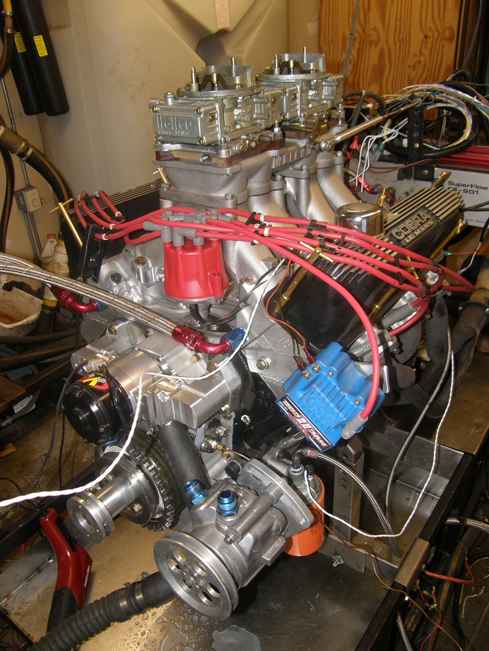
I would like to take this opportunity to point out the TRICK, gold Moroso T-handle valve cover hold downs I'm using on this engine ;D  They have been sitting in a box in my shop since the late 1970s.  Back when I first got my Shelby Mustang with the 428CJ in 1978, I thought it would be really cool to have those things holding on the valve covers.  (Don't laugh, I was just a kid...).  So, I went down to the local speed shop and bought a set.  Tried to put them on and discovered that they were for a 1/4-20 bolt, not the 5/16-18 bolts used for FE valve covers.  So, next I went to Sears and bought one of their deluxe tap and die sets (which I still have today, in fact...).  I drilled out the 1/4-20 threads in the T-handles and rethreaded them for 5/16-18, then went to the hardware store and bought some 5/16-18 all-thread, and cut it up to make studs for the T-handles to screw on to.  It was only after I had most of them installed that I discovered that the shock towers on my car interfered with the bottom front T-handle on each side, so only four of them on each side would screw on!  Not to be deterred, I went back to the hardware store and bought some springs that fit the outer diameter of the T-handles.  I cut the two T-handles that wouldn't fit in half, and slipped a spring over each half so that they would bend a little, and allow me use them next to the shock tower.  But you couldn't tighten them up very much that way, because the springs would slip on the T-handle shafts, so of course I ended up with a valve cover leak on each side  >:(  I lived with the leaks for about a month (sacrificing utility for style), but finally couldn't stand it anymore, tore off the T-handles and threw them in a box, figuring I'd use them some day.  Well, here it is, 39 years later, and I can finally use those god-forsaken things LOL!  I put the ones with the springs on them in the center top position on both sides, and what do you know, no leaks!

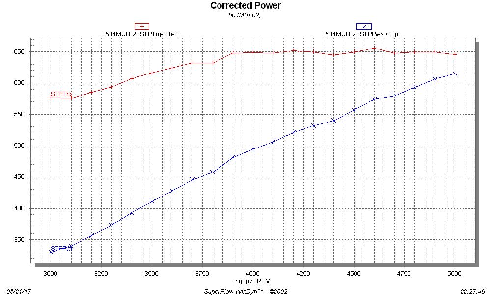
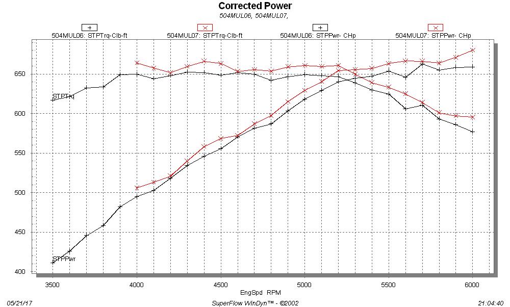
On Friday I finally got the engine up and running, and made a few dyno pulls.  As you can see from the photo I am starting off with the Weiand tunnel ram intake and my Holley 660 center squirter carbs, bolted onto one of my intake adapters.  Note that the water jacket passage on this intake adapter has been machined off and welded shut, and AN fittings have been screwed into the front of the intake adapter.  They lead to a remote thermostat housing.  At this point the engine is also fitted with a conventional ignition system, with an MSD 8594 distributor with mechanical advance, an MSD HVCII coil, and an MSD Digital 6 ignition box.  The headers are the common 1-3/4" primary Hooker Super Comps.  After some test runs I dialed in the carbs and timing, with 73 jets in all positions in the carbs, and 35 degrees total timing in the distributor.  The cam is fairly wild, as I expected; this engine is not very happy below about 2500 RPM, but it smooths out nicely after that and sounds really good in the dyno pulls.  The cylinder heads flowed a peak of 330 cfm, so I was expecting between 650 and 700 horsepower from this engine.  The graph below is the second dyno pull I made, without the fuel and timing completely dialed in yet, but as you can see this thing makes a whole bunch of torque with that tunnel ram:


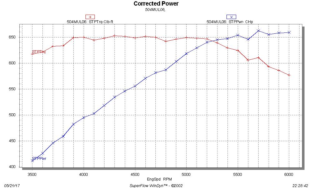
By the end of the day Friday I had the carbs and timing dialed in, and was up to about 660 horsepower; see the graph below:


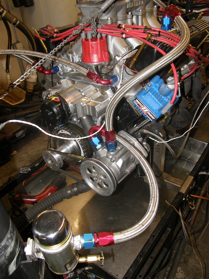
You may have noticed the vacuum pump on the front of the engine, which I had not yet hooked up.  On Saturday I set about doing that, machining a fitting that I was able to bolt onto the left side valve cover that would take a #12 AN line, and then running the lines from the valve cover to the pump, and from the pump to the evac can; see the picture below:


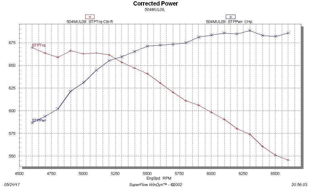
Crankcase vacuum was running about 11-12 inches with the engine running, which is just about where I wanted to be.  Adding the vacuum pump definitely added some power, as shown in the graph:


I started increasing the RPM range of the engine to find peak horsepower, and the best pull was the one shown below, making 688 HP peak:


At this point I stopped and checked the valve lash, which looked really good, and also changed oil.  I went to a heavier oil at this point, from 10W-30 to 20W-50, and didn't really think that it would have too much effect on the power output.  But power was down a bit on the next pull, maybe because the oil was heavier and also colder than the oil from the previous pull.  Also, I ran the pull from 4800 to 6800, and something was clearly happening past about 6500 RPM; see the graph:


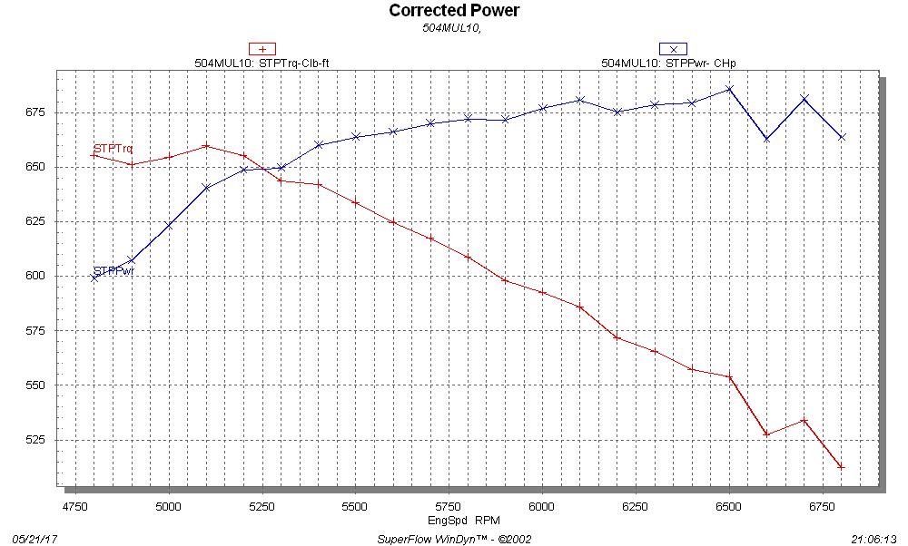
I'm pretty sure that this is valvetrain-related; I have seen this sort of thing before.  I have room on the springs to shim them up a little, and I may do that to get some more spring pressure and try to control the valves better, because I think the power fluxuations are being caused by poor valve control over 6500 RPM. 

So, I had dialed in the engine and run it with the vacuum pump, but I wanted to try a set of bigger carbs on the engine just in case they would lead to a horsepower and torque improvement.  My friend Kevin (thatdarncat) was over helping me today, and he brought his freshly rebuilt set of 850 center squirter carbs to test out.  We got the carbs installed on the engine, but then we encountered a starter problem, and by the time we got that fixed an exhaust leak problem came up, and it was getting late anyway, so we decided to call it a day.  We will run Kevin's carbs on the engine again tomorrow, and I may try one other thing, a different set of headers like the Hooker adjustable race headers.  I want to do everything I can to really dial this engine in, before I start all the other experiments.

After tomorrow, I will phase in the EFI system to control the ignition timing only, in steps as follows:

- First, hook the MSD distributor pickup to the EFI system, and have the EFI system trigger the MSD.  This will allow me to control timing directly from the timing table in the EFI software.

- Next, hook up the crank and cam sensors that I have installed in the front of the engine and time the engine from those; this way the distributor will only be distributing sparks, and will not affect the engine timing at all.

- Finally, remove the distributor and replace it with a "stub" distributor to run the oil pump, and go to eight individual coil packs triggered completely from the EFI system.  No distributor or MSD ignition box will be used.

I will go through the steps to make the changes above in excruciating detail, to try to make the EFI system hookup easy to understand.

It should be interesting to see what the effects will be on horsepower, if any, with these changes.  In the past I've seen a significant power increase when transitioning to the coil packs, and I'm curious as to whether that will be repeated on this engine.

Once the engine is in this configuration, I can bolt on any 351C intake manifold, without cutting it, and test it on the engine.  So, final steps will be test as many 351C intakes as I can.  I will try to post another update, with final results in this configuration and the EFI modifications complete, next weekend.
Jay Brown
- 1969 Mach 1, Drag Week 2005 Winner NA/BB, 511" FE (10.60s @ 129); Drag Week 2007 Runner-Up PA/BB, 490" Supercharged FE (9.35 @ 151)
- 1964 Ford Galaxie, Drag Week 2009 Winner Modified NA (9.50s @ 143), 585" SOHC
- 1969 Shelby Clone, Drag Week 2015 Winner Modified NA (Average 8.98 @ 149), 585" SOHC


cjshaker

  • Hero Member
  • *****
  • Posts: 4458
    • View Profile
Re: Dyno Mule to Test 351C Intakes on the Intake Adapter, Carb and EFI
« Reply #27 on: May 22, 2017, 08:24:53 AM »
First, I have to say, being a fan of the old school '70s look, that tunnel ram looks awesome on there! I think the coolest looking cars I ever saw as a kid always had one sticking through the hood. Can't say that about the valve cover T-bolts though ;D

Seems kind of odd that the issue past 6500 didn't show up on the previous dyno pull, which seemed to go to 6700 cleanly. The graph shows the issue starting at 6500. I wonder if the heavier/colder oil could be causing some timing issues, possibly causing the shaft to flex and disrupting the spark? It'll be interesting to see if it goes away when you shim the springs.

Is that copper line feeding into the fuel pump boss for a vacuum gauge for crankcase vacuum? I'd considered a vacuum pump for my next engine, but don't think the complexity and cost can be justified for 10-15 hp. I'm also very curious if the Hooker race headers will make a notable difference.
« Last Edit: May 22, 2017, 08:28:42 AM by cjshaker »
Doug Smith


'69 R-code Mach 1, 427 MR, 2x4, Jerico, 4.30 Locker
'70 F-350 390
'55 Ford Customline 2dr
'37 Ford Coupe

jayb

  • Administrator
  • Hero Member
  • *****
  • Posts: 7404
    • View Profile
    • FE Power
Re: Dyno Mule to Test 351C Intakes on the Intake Adapter, Carb and EFI
« Reply #28 on: May 22, 2017, 09:43:20 AM »
Actually pull #9 only went to 6600 RPM, and the last data point seemed a bit out of line.  Its never a good idea to trust the last data point on the dyno sheet, because the brake is coming on somewhere around there and it can have an effect on the reading.  But its possible the oil was the culprit.  When I run it again we'll see what happens.

The copper line is indeed a line to a pressure sensor to monitor crankcase vacuum.  I think that the general rule of thumb for vacuum pumps is they work the best on larger engines with low tension ring packages, so you might not see a big improvement with your engine.  On the 510" FE in my Mach 1, right after Drag Week in 2005, I was at Cedar Falls Raceway and ran 10.60 without the vacuum pump, and then 10.45 with the pump on the very next pass.  That tenth and a half was worth adding the pump to me...
Jay Brown
- 1969 Mach 1, Drag Week 2005 Winner NA/BB, 511" FE (10.60s @ 129); Drag Week 2007 Runner-Up PA/BB, 490" Supercharged FE (9.35 @ 151)
- 1964 Ford Galaxie, Drag Week 2009 Winner Modified NA (9.50s @ 143), 585" SOHC
- 1969 Shelby Clone, Drag Week 2015 Winner Modified NA (Average 8.98 @ 149), 585" SOHC


machoneman

  • Hero Member
  • *****
  • Posts: 3851
    • View Profile
Re: Dyno Mule to Test 351C Intakes on the Intake Adapter, Carb and EFI
« Reply #29 on: May 22, 2017, 09:48:56 AM »
Nice Jay! That t-ram looks terrific. With some shimming (or different springs, maybe beehives and tiny retainers?) and those race headers, I'll bet over 700 hp, 705 my guess.
Bob Maag