Author Topic: FE Intake Adapter  (Read 328342 times)

0 Members and 1 Guest are viewing this topic.

cjshaker

  • Hero Member
  • *****
  • Posts: 4474
    • View Profile
Re: FE Intake Adapter
« Reply #255 on: July 28, 2013, 11:51:12 PM »
How do the oblong holes help with the wider valve spacing on MR heads when the oblong hole is vertical and not horizontal? Am I missing something obvious here? Also, the bolt holes look like they get real cozy with the number 1 & 8 port. Are you worried about being able to get a good seal there with high vacuum?

The finish quality looks great....and really shows what all manufacturers go through to produce a quality product. At least the ones that DO produce a quality product. I salute your unrelenting pursuit of perfection. It really shows in your finishing touch-ups. Once you get that code set, I think I would back it up on 3 external hard-drives, kept in a safe.....with an armed guard  ;)
Doug Smith


'69 R-code Mach 1, 427 MR, 2x4, Jerico, 4.30 Locker
'70 F-350 390
'55 Ford Customline 2dr
'37 Ford Coupe

jayb

  • Administrator
  • Hero Member
  • *****
  • Posts: 7436
    • View Profile
    • FE Power
Re: FE Intake Adapter
« Reply #256 on: July 29, 2013, 07:35:55 AM »
Doug, on the pushrod holes the situation is like this:  Standard FE valve spacing is 2.00", and medium riser spacing is 2.100".  Interestingly enough, my Edelbrock heads split the difference at 2.05".  Anyway, I wanted to use the medium riser spacing for the pushrod holes because that would allow for the widest port.  But this leaves the pushrods towards the inboard side of the holes for a standard FE head.  This would be fine, except that as I'm sure you know, the pushrods don't stay in a fixed location during valvetrain movement; as the rocker arm moves, the pushrods move towards the top and bottom of the hole in the intake.  With a round hole, and the pushrod moved towards the port, there isn't much room for the pushrod to move towards the top and bottom; it starts to hit the curvature of the pushrod hole.

However, if I make the hole oblong up and down, the pushrod can be biased towards the port side of the hole, and it will have more clearance when it moves towards the top and bottom of the hole.  It is moving along the straight section of the oblong hole, rather than into a curved section of a round hole.

This is kind of hard to explain; I hope you see what I mean.  It's all clear when the valvetrain is mocked up and you watch what is happening...

On the intake bolt holes, you are correct that the sealing area between the FE bolt counterbore and the 351C port is pretty small, but I think it is sufficient; it measures 0.110".  There is not much to be done about that; the FE intake bolt hole locations are fixed, and the 351C 4V port locations are fixed.  I have made the counterbore on those two FE intake bolts as small as practical, and in fact in those two positions the counterbores are oblong like the pushrod holes, in order to narrow them up and provide as much meat as possible between the counterbore and the port.  Getting this dimension the same between the #1 port and the #8 port was a challenge, and I had to relocate the 351C intake bolt holes on the intake adapter a couple of times to make it right.  One potential way to eliminate this as a consideration is to seal the intake bolt that goes into those two counterbored holes.  If the head of the bolt has some sealer underneath and it prevents vacuum leaks into the bolt hole, then you would no longer be relying on the thin area between the counterbore and the port to seal; you would have the rest of the gasket area, which extends well around the counterbored area, as a seal.

Thanks for the kind words on the development work; it has taken quite a bit longer than I anticipated to get the machining programs right, but I think I am really close now.  I've bought plenty of FE parts over the years that are substandard quality and don't fit, or leak, whatever, and I want to make sure that these intake adapters are better than that...
Jay Brown
- 1969 Mach 1, Drag Week 2005 Winner NA/BB, 511" FE (10.60s @ 129); Drag Week 2007 Runner-Up PA/BB, 490" Supercharged FE (9.35 @ 151)
- 1964 Ford Galaxie, Drag Week 2009 Winner Modified NA (9.50s @ 143), 585" SOHC
- 1969 Shelby Clone, Drag Week 2015 Winner Modified NA (Average 8.98 @ 149), 585" SOHC


cjshaker

  • Hero Member
  • *****
  • Posts: 4474
    • View Profile
Re: FE Intake Adapter
« Reply #257 on: July 29, 2013, 08:32:31 AM »
I see what you mean with the holes. I was picturing different valve spacing as needing a horizontal oblong. But moving the rounded part verticaly away from center effectively does the same thing, gaining additional clearance.

As for the bolt holes, as long as a stout gasket is used, it shouldn't be a concern. Also, I was picturing a very thin gasket in that area, which shouldn't be the case. Since the holes are countersunk, the gasket should retain its lateral thickness and strength in that area. Again, I wasn't thinking clearly about it. Maybe a small instruction sheet with suggestions thrown in with the delivered intake would help with any minor concerns.
Doug Smith


'69 R-code Mach 1, 427 MR, 2x4, Jerico, 4.30 Locker
'70 F-350 390
'55 Ford Customline 2dr
'37 Ford Coupe

WConley

  • Hero Member
  • *****
  • Posts: 1170
  • No longer walking funny!
    • View Profile
Re: FE Intake Adapter
« Reply #258 on: July 29, 2013, 05:25:35 PM »
Very nice work Jay.  Big thumbs up for your persistence!

- Bill
A careful study of failure will yield the ingredients for success.

turbohunter

  • Hero Member
  • *****
  • Posts: 2509
    • View Profile
Re: FE Intake Adapter
« Reply #259 on: July 29, 2013, 06:10:52 PM »
We mortals peer out of our respective caves towards the mount and wonder if ever we dare such heights. Then we lower our eyes and shake our heads as reality sets in.
Congratulations on your achievement. It's really quite beautiful.

A bit dramatic but what the hell, you deserve it. ;)
Marc
'61 F100 292Y
'66 Mustang Injected 428
'66 Q code Country Squire wagon


jayb

  • Administrator
  • Hero Member
  • *****
  • Posts: 7436
    • View Profile
    • FE Power
Re: FE Intake Adapter
« Reply #260 on: August 04, 2013, 09:15:00 PM »
Well, it sure has been a long time getting to this point, but finally today my efforts on this project culminated in some dyno data.  The week started off inauspiciously enough, though, when my second CNC machine went down pretty hard on Tuesday.  I needed this machine because my big one is set up to do the majority of the work on the intake adapters, and for the center access cover and road draft tube cover I'm relying on the smaller machine.  Also, for the fixtures I need to drill the holes for the thermostat housing and pipe plug on the front of the intake, I had been planning on using the smaller machine.  After troubleshooting it all week I finally figured out on Saturday that one of the servo motor driver cards had gone bad, so at least I know what is wrong now.  But I didn't get the remaining access covers or the fixtures machined, of course.  Next week I will have to see about getting a replacement motor driver card.

During the week when I was in the shop the big CNC machine continued to plug along on the fourth intake casting.  Although the third casting was usable, I decided to wait for the fourth casting to actually put on the engine and dyno test, because the third casting still had some minor machining mistakes.  But around 11:00 PM on Thursday, the machine finished the fourth casting, and it looked great.  I pulled it off the machine, cleaned it off, and stamped it 001:


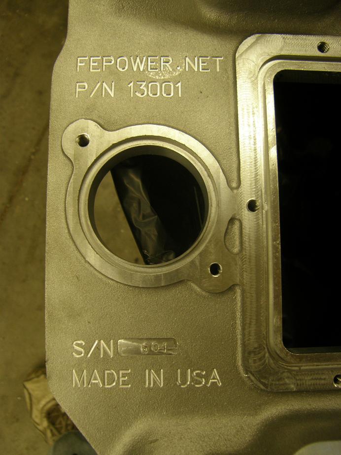
Finally!  I was really happy with the way it came out.  Friday night I started the fifth casting on the big machine, and continued to work on the smaller one.  But after I found the problem on Saturday, and realized that there was no way I would be able to machine the fixtures required to drill and tap the holes in the front of the intake, it seemed that I would have to wait another week to get the small machine fixed, build the fixtures, drill and tap the manifold with the fixtures, and then run the manifold on the dyno.

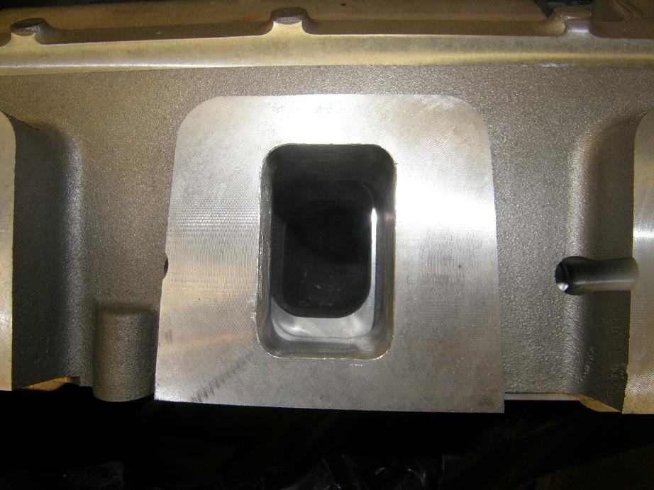
This morning when I woke up I decided I just couldn't wait that long.  I decided to mark the holes in the manifold by hand, and drill and tap them by hand, just so I could get the manifold on the dyno mule.  I was as careful as I could be and still got the 3/8" pipe thread in a little crooked, but the thermostat housing fit on the manifold so by noon today I was good to go.  I decided to port match the manifold on the FE side to the Cobra Jet heads of the dyno mule, on the roof and the sides of the port, but not the floor.  I test fit the manifold and marked it, and then did the port matching, which really involved only taking about .050" off one side of each of the ports.  I also cleaned up all the CNC porting marks in the intake adapter ports with an abrasive roll; here's a before and after pic:


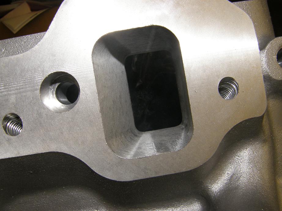
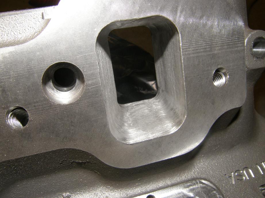
I decided to test the 351C Performer RPM first, and I knew there would be a big port mismatch at the manifold and intake adapter interface, since the intake adapter has ports sized like a 4V Cleveland and the Performer RPM has the 2V ports.  I bolted the Performer RPM onto the intake adapter and flipped it over; here's a picture of the port mismatch:


That is a pretty significant mismatch, and coupled with the other mismatch between the CJ low riser style ports and the medium riser ports in the intake adapter, I wondered how much this would affect the power production of this engine.  The saving grace was that this engine is not really intake limited, it is cam limited, so I was hoping that despite these two big steps in each runner that the manifold would still perform well on this engine.

After getting done with the port matching and cleanup I installed the intake on the engine with some good sealer and gave it until 6:00 PM tonight to set up.  Here's a picture of the intake adapter installed at this point:


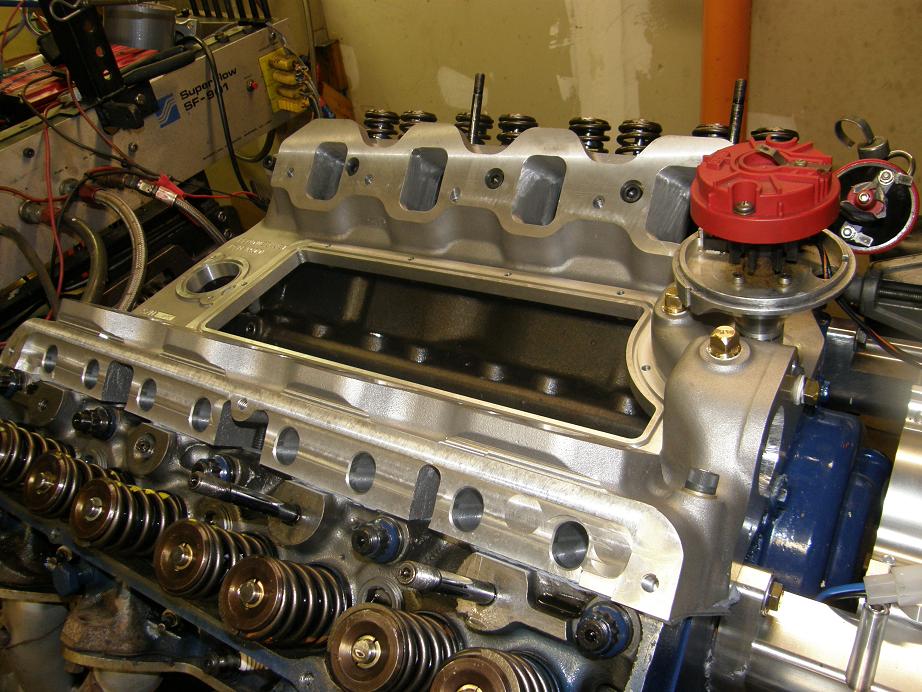
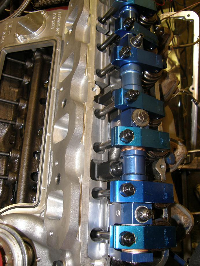
At 6:00 PM I hooked up the thermostat housing to the engine and filled it with water.  This was cool, because with only the intake adapter in place I could look into the valley of the engine for any potential water leaks.  Never been able to do that before LOL!  Everything was sealed up nice so I continued with the assembly.  Here's a few pictures taken along the way:


When I got to the clamp holding the distributor down, though, I got an unpleasant surprise.  The flat part of the manifold was not big enough for the clamp to fit like it does on a stock intake.  Here's a picture:


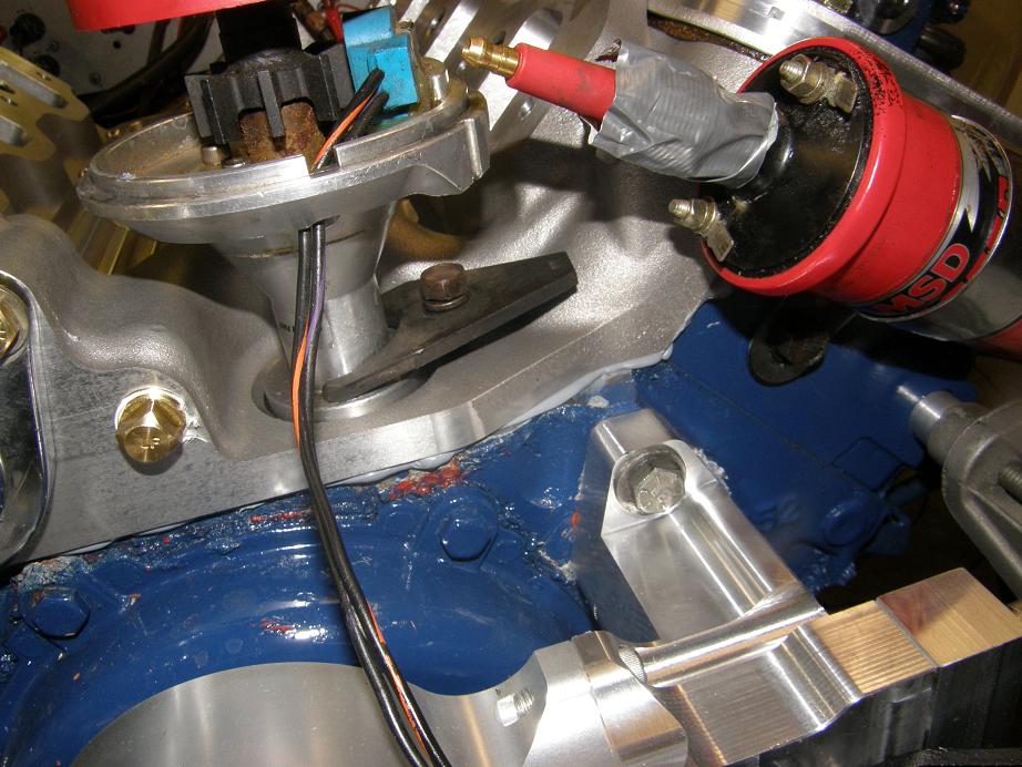
Dammit!  A pretty minor issue to be sure, but still...  What I will have to do is supply a custom billet distributor hold down with each intake.  This will be no big deal; I can machine it at the same time that the access cover and road draft tube cover are machined, and there is room in the stock for the clamp.  I suppose no one will object to a little more bling with their intake adapter LOL!

It was 7:30 and the truth was at hand.  The engine was assembled with exactly the same parts as the last time I ran it in May, with the exception of swapping out the FE Performer RPM with the intake adapter plus the 351C Performer RPM.  Timing, fuel, everything was the same.  Even the atmospheric conditions were close.  The engine started with no difficulty, and I warmed it up to the same water and oil temperature as the dyno pull in May, then ran the test.  Here are the results:


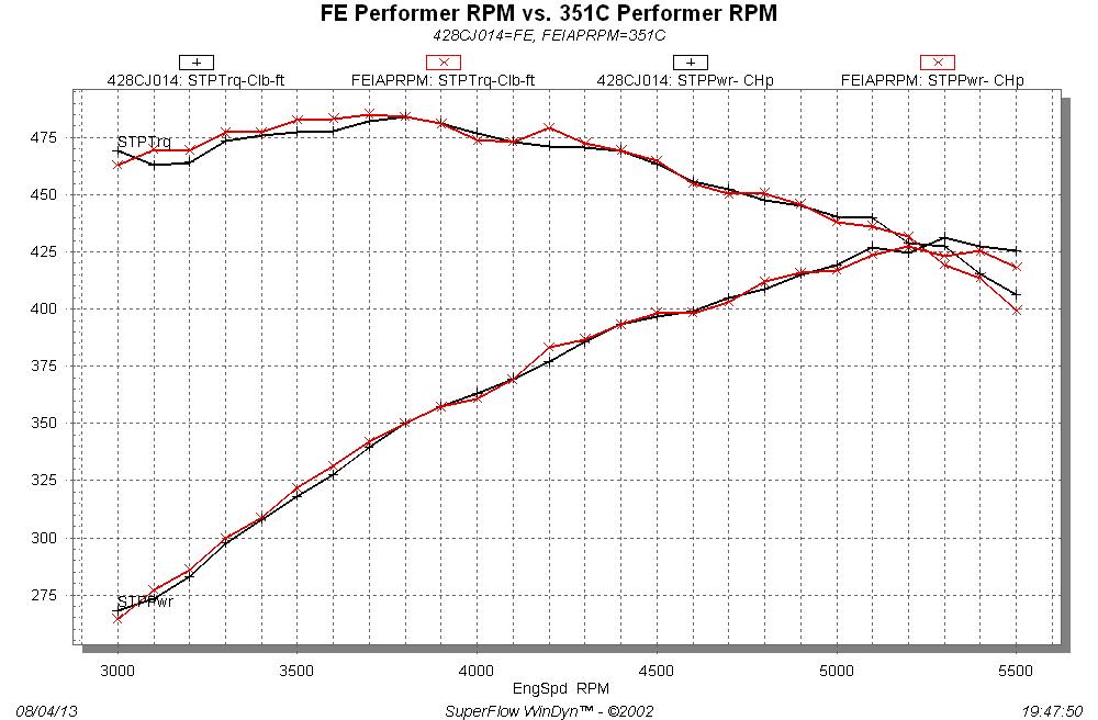
Sheesh, you can hardly even tell the difference between them!  I checked all the numbers and they look like this:

FE Performer RPM:

Peak Torque -- 483.9@3800 RPM
Peak Horsepower -- 431.3@5300 RPM
Average Torque 3000-5500  -- 458.9 lb-ft
Average Horsepower 3000-5500  -- 368.8 HP


FE Intake Adapter + 351C Performer RPM:

Peak Torque -- 485.2@3700 RPM
Peak Horsepower -- 427.3@5200 RPM
Average Torque 3000-5500  -- 459.4 lb-ft
Average Horsepower 3000-5500  -- 369.0 HP

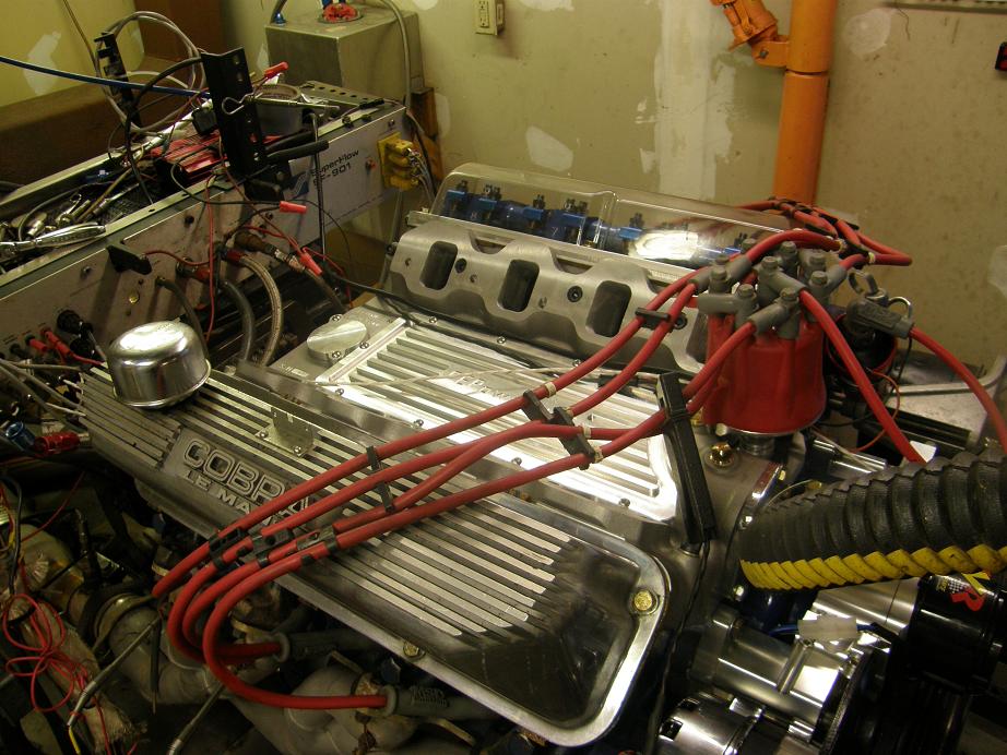
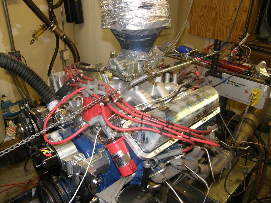
These numbers are so close that I don't think you could tell the difference on the street or at the track.  Boy, after all this if my manifold adapter had flopped on the dyno I would have been pretty unhappy LOL!  But it did just about what I expected it to do, and maybe even a little better.  Here's a picture of the engine taken after the dyno pull, with the 351C Performer RPM installed:


Next weekend I'm going to test the other two 351C intakes I have here, the Edelbrock Torker and the Weiand tunnel ram.  I would expect to get similar results.  In fact, I may do a cam change before I run those tests, because the hydraulic lifters really kill the power of this engine starting at around 5300 RPM, and it would be nice to see how it behaves up to 6000 RPM with the other intakes.  Besides, I want to try changing cams without pulling the intake LOL!  I have a Comp 282S and a Comp 294S sitting on the shelf.  Decisions, decisions. 

Also next weekend I'll post information on how to get on the list for purchasing one of these intake adapters, in case you are interested.  Thanks to all you guys for the continued interest in this project!

Jay Brown
- 1969 Mach 1, Drag Week 2005 Winner NA/BB, 511" FE (10.60s @ 129); Drag Week 2007 Runner-Up PA/BB, 490" Supercharged FE (9.35 @ 151)
- 1964 Ford Galaxie, Drag Week 2009 Winner Modified NA (9.50s @ 143), 585" SOHC
- 1969 Shelby Clone, Drag Week 2015 Winner Modified NA (Average 8.98 @ 149), 585" SOHC


Bullitt

  • Newbie
  • *
  • Posts: 19
    • View Profile
Re: FE Intake Adapter
« Reply #261 on: August 04, 2013, 11:16:27 PM »
That is incredibly awesome!

Josh

427Fastback

  • Hero Member
  • *****
  • Posts: 605
    • View Profile
Re: FE Intake Adapter
« Reply #262 on: August 04, 2013, 11:46:18 PM »
Pretty good numbers considering the port alignment (or lack of)...I look forward to the other tests...I still plan on buying two of them.....Cory
1968 Mustang Fastback...427 MR 5spd (owned since 1977)
1967 Mustang coupe...Trans Am replica
1936 Diamond T 212BD
1990 Grizzly pick-up

WConley

  • Hero Member
  • *****
  • Posts: 1170
  • No longer walking funny!
    • View Profile
Re: FE Intake Adapter
« Reply #263 on: August 05, 2013, 12:03:29 AM »
Woo-hoo!!  Glad it all came together Jay :-)   I bet that dyno data was gratifying to see.  Very nice work.  You can see the quality and attention to detail.

- Bill
A careful study of failure will yield the ingredients for success.

machoneman

  • Hero Member
  • *****
  • Posts: 3856
    • View Profile
Re: FE Intake Adapter
« Reply #264 on: August 05, 2013, 08:06:24 AM »
Yeah, Jay! Hey, didn't know that the pushrod holes could be that big. Neat but I'd like to see one of those Parker Funnelwebs or really tall 351C single planes run up.
Bob Maag

jayb

  • Administrator
  • Hero Member
  • *****
  • Posts: 7436
    • View Profile
    • FE Power
Re: FE Intake Adapter
« Reply #265 on: August 05, 2013, 08:20:46 AM »
I'll get those manifolds tested, but not on this engine.  This engine is cam and compression limited, and all the high power manifolds will look the same on it.  You can see this if you look at the horsepower data for the 428CJ in my book.  All the really good manifolds are clustered at the top of the list within a few horsepower of each other.  So, there isn't really a good way to discriminate between them.

I need to put my 600 HP dyno mule back on the pump, and then start testing a variety of the 351C intakes.  That would really tell us which manifolds work in a higher power application...
Jay Brown
- 1969 Mach 1, Drag Week 2005 Winner NA/BB, 511" FE (10.60s @ 129); Drag Week 2007 Runner-Up PA/BB, 490" Supercharged FE (9.35 @ 151)
- 1964 Ford Galaxie, Drag Week 2009 Winner Modified NA (9.50s @ 143), 585" SOHC
- 1969 Shelby Clone, Drag Week 2015 Winner Modified NA (Average 8.98 @ 149), 585" SOHC


machoneman

  • Hero Member
  • *****
  • Posts: 3856
    • View Profile
Re: FE Intake Adapter
« Reply #266 on: August 05, 2013, 10:31:32 AM »
Thanks Jay. Yes, the motor under those intakes s/b pretty wild.

Have you thought about using a 351W or maybe a 351C ditzy hold-down instead?

They are only a tad longer than 1.25" or so. 

http://www.summitracing.com/parts/mrg-9860?seid=srese1&gclid=CI20pbvP5rgCFSJqMgod7kEAGA

http://www.summitracing.com/parts/mrg-2502/overview/make/ford

Heck, a BBC unit might work too.

http://www.ebay.com/itm/Moroso-SBC-BBC-Chevy-HEI-Distributor-Hold-Down-Clamp-/190826851758#ht_672wt_679
« Last Edit: August 05, 2013, 10:41:35 AM by machoneman »
Bob Maag

LargeRickhead66

  • Newbie
  • *
  • Posts: 19
    • View Profile
Re: FE Intake Adapter
« Reply #267 on: August 05, 2013, 12:22:42 PM »
Thanks Jay for all of your applied knowledge and skill. I've been drooling over this adapter since you started the project. Keep testing and posting, and above all make sure I'm on the list for at least one!  Rick Wanner

jayb

  • Administrator
  • Hero Member
  • *****
  • Posts: 7436
    • View Profile
    • FE Power
Re: FE Intake Adapter
« Reply #268 on: August 05, 2013, 09:34:33 PM »
Thanks Jay. Yes, the motor under those intakes s/b pretty wild.

Have you thought about using a 351W or maybe a 351C ditzy hold-down instead?

They are only a tad longer than 1.25" or so. 

http://www.summitracing.com/parts/mrg-9860?seid=srese1&gclid=CI20pbvP5rgCFSJqMgod7kEAGA

http://www.summitracing.com/parts/mrg-2502/overview/make/ford

Heck, a BBC unit might work too.

http://www.ebay.com/itm/Moroso-SBC-BBC-Chevy-HEI-Distributor-Hold-Down-Clamp-/190826851758#ht_672wt_679

Those are good suggestions on the distributor hold downs, Bob, especially since I checked this morning and it turns out that I DON'T have room for adding a distributor hold down to the piece of aluminum I'm using for the access panel and road draft tube cover, like I originally thought I did.  Thought I had more room than I do there; good thing I measured.  So if I were to make a distributor hold down I'd have to start with a new piece of aluminum.  I think I will order some of those parts for the other engines and see if they might work...
Jay Brown
- 1969 Mach 1, Drag Week 2005 Winner NA/BB, 511" FE (10.60s @ 129); Drag Week 2007 Runner-Up PA/BB, 490" Supercharged FE (9.35 @ 151)
- 1964 Ford Galaxie, Drag Week 2009 Winner Modified NA (9.50s @ 143), 585" SOHC
- 1969 Shelby Clone, Drag Week 2015 Winner Modified NA (Average 8.98 @ 149), 585" SOHC


ToddK

  • Sr. Member
  • ****
  • Posts: 437
    • View Profile
Re: FE Intake Adapter
« Reply #269 on: August 05, 2013, 09:53:42 PM »
Looking good Jay. With the distributor hold down, is it possible to move the bolt hole a bit further toward the front of the adapter? That may give a bit more clearance.

Looking forward to further testing and also development of an adapter to work with BT HR heads.