Author Topic: FE Intake Adapter  (Read 325820 times)

0 Members and 1 Guest are viewing this topic.

jayb

  • Administrator
  • Hero Member
  • *****
  • Posts: 7390
    • View Profile
    • FE Power
FE Intake Adapter
« on: October 07, 2012, 03:37:28 PM »
Thought I'd start a topic on this so that anyone who wants to see progress on this project can check in here.  Since this product is an item I expect to sell in a few months, I'm not all that comfortable putting it in the Member Projects section; my initial inclination was to put it in the Vendor Classifieds.  However, since the process is technically oriented and certainly qualifies as a member project, I thought I would put it here to start.  If you guys object let me know, and I'll move it.

First step in the design process was to make a drawing of the intake adapter manifold that I wanted.  I took a bunch of measurements off of several other manifolds since I didn't have any access to an FE intake blueprint, and did a two dimensional drawing of the part.  Then I engaged the services of a local design consultant, who works a lot with castings.  He used to work at a local casting company and is familiar with all the ins and outs of casting design, for example shrink of the casting after pouring, draft required to get the cores out of the molds, etc.  He does his design work in Solidworks, which seems to be the program that most people favor for 3D CAD work these days.  He took my two dimensional drawings and after a couple of revisions came up with the following 3D drawing:
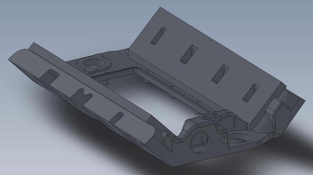


This is a drawing of a partially machined casting, the ports are not finished and the pushrod holes and some of the bolt holes are not shown.  The port configuration will depend on what manifold is run on the intake.  For example, a standard 351C intake manifolds will get a certain port configuration, the Yates style manifolds will get a different one.

Through this initial design process several things became apparent.  My original plan was going to be to make this manifold suitable for use as a medium riser or high riser (with the associated change in the valve cover rail), or have it be able to be machined as a tunnel port.  First pass on the drawing showed that to be unrealistic.  The reason was the weight of the casting and the machining time.  In order to leave the port openings completely out of the casting (so it could be used for a tunnel port base), and to raise the valve cover rail so it could be machined as a high riser, the weight of the casting went up by nearly 10 pounds!  This blew the financial side of the project out the window; I want to be able to sell these for right around $400, and the extra material cost plus the extra machining cost for the medium riser version (which I would expect to sell the most of) made this an impossible target.  So, I decided to focus for now on the medium riser design, and do a separate (and more expensive) version that could be machined as a high riser or tunnel port later.

Another thing that became obvious after I purchased and measured several different types of 351C intakes was that all of them would need to be modified or machined in some way in order to fit on this adapter.  In some cases the modifications are trivial and can be done with a hacksaw; for example, the Weiand 351C tunnel ram is this way.  Others, such as the 351C intakes for Yates style cylinder heads, such as the Edelbrock 2991 and 2865 (Glidden Victor) will require a different bolt pattern and a thinner flange on the intake adapter, plus extensive machining on the valley area of the Edelbrock intake in order to fit.  This is going to be a one at a time process for me, to develop the machining operations required on the intake adapter to make some of these manifolds fit.  Also, since some of these will require extensive work on the manifolds themselves, I decided that I would have to offer that service for the manifolds also. 

Along with the fit issues with the different intakes, there are also different port configurations.  So, one port configuration in the intake adapter will definitely not fit all.  This makes them a little bit less flexible; unless you go with the stock type 351C 4V intakes, you won't be able to swap a lot of intakes back and forth.  When I looked into the 351C intake picture I was really surprised at how much variation there was; the small block stuff seems to have multiple port locations (raised ports in particular), plus more than one bolt pattern depending on the heads that are used. 

The conclusion was that what this adapter really needs is a specific intake manifold designed to work with it, rather than trying to make some variety of 351C intakes work.  Unfortunately that's a ways down the road; I need to get the adapter manufactured before I can think about making an upper manifold for it.  But at this point I think a dedicated upper manifold or two would be a great addition.

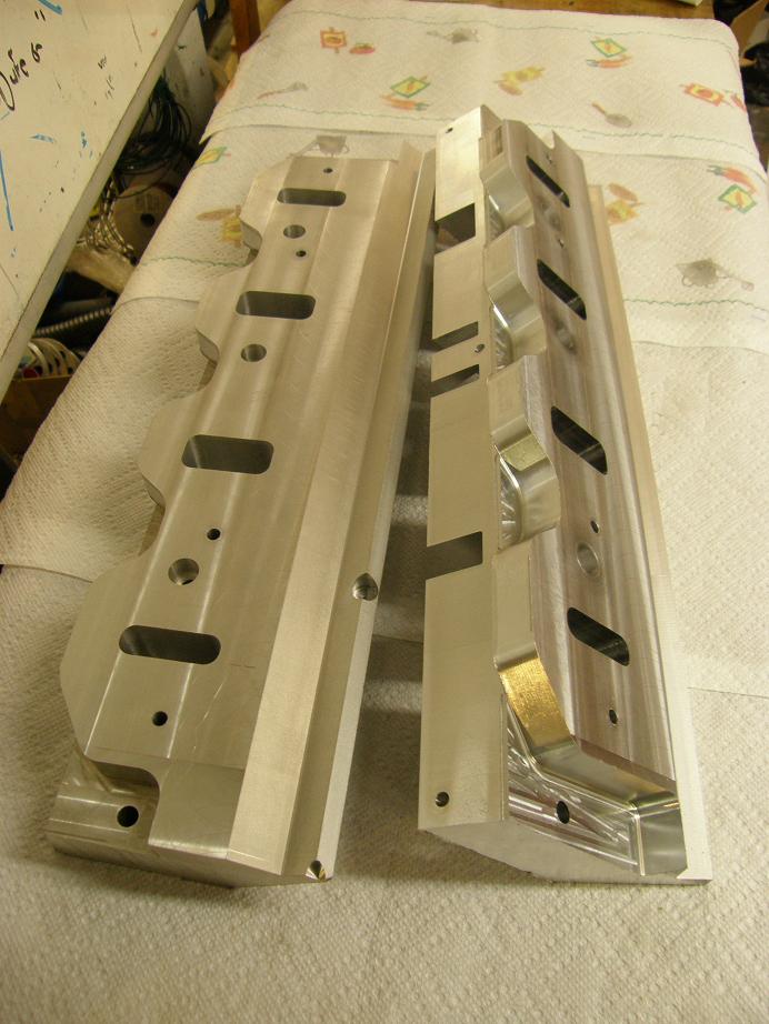
Back to the drawing, which of course you can't bolt onto the engine.  As a result, to check the drawing I decided to machine some billet plates with many of the key dimensions of the drawing machined in, to check the fit on a mocked up FE.  I'm set up and running now on my new CNC machine, and am starting to get used to writing programs with it, but it still took me the better part of two weeks to write the programs and get the two plates machined.  Made some mistakes along the way, but overall I got the key dimensions right.  Here is a photo of the two plates, the second of which I just finished up last night:


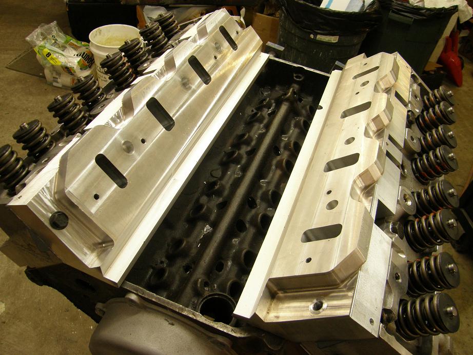
Today I got a spare block and set of Edelbrock heads mocked up, and bolted the plates on to check the fit.  I needed to make a slight modification on the drawing with respect to the angle of the valve cover rail, but other than that there were no issues bolting the plates onto the heads:


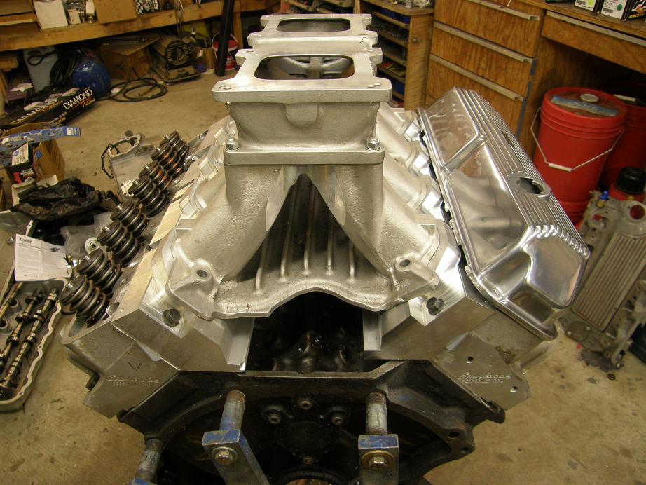
Finally I topped the setup off with the 351C tunnel ram to check port alignment and fit.  This was a little more problematic, since I have limited data on 351C engines.  I had to move around some of the mounting holes on the drawing to get them lined up with the intake.  I also had to machine the thickness of the plates down somewhat, because the manifold originally sat too high on the plates.  One of the complications here was the thickness of the 351C intake manifold gaskets.  The Mr. Gasket versions were a full 0.110" thick, while the Fel-Pros were a little more standard .062" (like the FE intake gaskets).  I don't know how to address this except to live with these tolerances, but I will probably recommend a specific gasket for best fit of the intake on the adapter. 

Finally I got the thickness about right and was able to get the 351C manifold positioned on the adapter so it looked like it would fit.  Here's a picture of the tunnel ram sitting on the engine:


Next steps are to get the 3D drawing modified to reflect what the test plates have told me, then its off to the pattern shop with the drawings to make the patterns for the casting sand.  That is about a 6-8 week process with the shop that I am going to use.  After that, I should be able to get five prototypes cast, and then I can work on the complete machining program.  We will see what happens as this projects proceeds...
Jay Brown
- 1969 Mach 1, Drag Week 2005 Winner NA/BB, 511" FE (10.60s @ 129); Drag Week 2007 Runner-Up PA/BB, 490" Supercharged FE (9.35 @ 151)
- 1964 Ford Galaxie, Drag Week 2009 Winner Modified NA (9.50s @ 143), 585" SOHC
- 1969 Shelby Clone, Drag Week 2015 Winner Modified NA (Average 8.98 @ 149), 585" SOHC


Heo

  • Hero Member
  • *****
  • Posts: 3278
    • View Profile
Re: FE Intake Adapter
« Reply #1 on: October 07, 2012, 05:10:39 PM »
Cant wait for the finished product 8)


The defenition of a Gentleman, is a man that can play the accordion.But dont do it

My427stang

  • Hero Member
  • *****
  • Posts: 3914
    • View Profile
Re: FE Intake Adapter
« Reply #2 on: October 07, 2012, 06:34:38 PM »
I am digging that more every time I see it

---------------------------------
Ross
Bullock's Power Service, LLC
- 70 Fastback Mustang, 489 cid FE, Victor, SEFI, Erson SFT cam, TKO-600 5 speed, 4.11 9 inch.
- 71 F100 shortbed 4x4, 461 cid FE, headers, Victor Pro-flo EFI, Comp Custom HFT cam, 3.50 9 inch

WConley

  • Hero Member
  • *****
  • Posts: 1157
  • No longer walking funny!
    • View Profile
Re: FE Intake Adapter
« Reply #3 on: October 07, 2012, 07:16:55 PM »
Nice Job Jay on making up those machined test pieces.  No matter what you do on paper or in CAD, there is always a surprise with the first physical pieces.  It's nice to catch that stuff so early in the game!

Looking forward to more updates :-)

- Bill
A careful study of failure will yield the ingredients for success.

427Fastback

  • Hero Member
  • *****
  • Posts: 603
    • View Profile
Re: FE Intake Adapter
« Reply #4 on: October 11, 2012, 10:24:38 PM »
Very nice....I look forward to the finished product.....Cory
1968 Mustang Fastback...427 MR 5spd (owned since 1977)
1967 Mustang coupe...Trans Am replica
1936 Diamond T 212BD
1990 Grizzly pick-up

machoneman

  • Hero Member
  • *****
  • Posts: 3845
    • View Profile
Re: FE Intake Adapter
« Reply #5 on: October 12, 2012, 07:57:06 AM »
The pieces look great Jay! Look forward to the first pics of the finished adaptor.

I did see that TMeyer over at the Cleveland Forum is engaged with making a new Track Boss 302 single plane intake. While a 351 Track Boss with the 9.2" deck height is what you'll need, note that Joe speaks about just how good the original TB was. 

http://www.network54.com/Forum/119419/message/1350013331/A+little+FYI...

http://www.network54.com/Forum/119419/message/1350043371/The+B+%26amp%3B+A+Track+Boss+intake+is+one+of+the+best+flowing

http://www.tmeyerinc.com/B&Aintake.html
« Last Edit: October 12, 2012, 08:35:31 AM by machoneman »
Bob Maag

lovehamr

  • Full Member
  • ***
  • Posts: 209
    • View Profile
Re: FE Intake Adapter
« Reply #6 on: October 26, 2012, 08:04:19 AM »
Jay that project is looking great! 

If you have any need of it, I have a single plane intake for the old Motorsport C302 heads that I ran on a Clevor for years.  If you could use it for paterning or anything just let me know.

Steve

jayb

  • Administrator
  • Hero Member
  • *****
  • Posts: 7390
    • View Profile
    • FE Power
Re: FE Intake Adapter
« Reply #7 on: October 26, 2012, 01:11:59 PM »
Thanks for the offer Steve, I'll keep that in mind - Jay
Jay Brown
- 1969 Mach 1, Drag Week 2005 Winner NA/BB, 511" FE (10.60s @ 129); Drag Week 2007 Runner-Up PA/BB, 490" Supercharged FE (9.35 @ 151)
- 1964 Ford Galaxie, Drag Week 2009 Winner Modified NA (9.50s @ 143), 585" SOHC
- 1969 Shelby Clone, Drag Week 2015 Winner Modified NA (Average 8.98 @ 149), 585" SOHC


smokin427

  • Newbie
  • *
  • Posts: 3
    • View Profile
Re: FE Intake Adapter
« Reply #8 on: November 10, 2012, 03:35:04 AM »
Jay:
  If you had to make a wild guess, how long bfore I could buy at any price, a raised port high riser base from you ? I am very frustrated since I built my 427 high riser with a Dove large plenum single plane  raised port dual quad intake and now hav very little mid range power. I am in the process of raising the ports on my dual plane Ford 2x4 high riser intake and putting it back on to get my mid range back. I have a friend who can modify the Ford dual plane into a single plane like he runs on his Tbolt and I may try that if I can find another Ford dual plane 2x4 high riser to modify. If I can get one of your bases, I have a friend who has a CNC Mill and is a master at solid works and the mill and could make a top intake to fit your base that has the high riser carb centerkine spacing and would be the height I need to fit under my hood (it has an oval hole in it for the air cleaner to stick out) on my 66 Fairlane daily driver. If possible could you email me at mike.levin@mindspring.com with a phone number. I would love to talk with you in person.  Thanks

jayb

  • Administrator
  • Hero Member
  • *****
  • Posts: 7390
    • View Profile
    • FE Power
Re: FE Intake Adapter
« Reply #9 on: November 10, 2012, 08:38:52 AM »
At this point I would say next April or May for the high riser or tunnel port versions of the intake adapter.  I'm hoping to have the medium riser version ready to go by March, and the HR/TP would come right after that.  You can send me a personal message on the forum, or email me at jayb@fepower.net if you want to talk further - Jay
Jay Brown
- 1969 Mach 1, Drag Week 2005 Winner NA/BB, 511" FE (10.60s @ 129); Drag Week 2007 Runner-Up PA/BB, 490" Supercharged FE (9.35 @ 151)
- 1964 Ford Galaxie, Drag Week 2009 Winner Modified NA (9.50s @ 143), 585" SOHC
- 1969 Shelby Clone, Drag Week 2015 Winner Modified NA (Average 8.98 @ 149), 585" SOHC


Ford428CJ

  • Sr. Member
  • ****
  • Posts: 383
  • FE FREAK!
    • View Profile
    • Hillside Auto
Re: FE Intake Adapter
« Reply #10 on: November 12, 2012, 10:08:47 AM »
Very nice Jay! Glad to see someone making cool stuff for the FE! 8)
Wes Adams FORD428CJ 
03 F-250 Crew Cab 4x4 6.0 and 35's
64 Falcon 428FE
55 FORD Truck 4-link Rides on air with 428FE
http://www.hillsideauto.org/

jayb

  • Administrator
  • Hero Member
  • *****
  • Posts: 7390
    • View Profile
    • FE Power
Re: FE Intake Adapter
« Reply #11 on: December 02, 2012, 05:24:23 PM »
Things have gone WAY, WAY too slow on the project for my liking, but I'm finally to the point where the basic design is finished and I am currently out shopping it around to pattern shops and casting foundries.  Here's a picture of the finished manifold 3D model.  The parts colored in red, like the bolt holes and the machined groove for the O-ring around the center opening, will be machined, not cast.  Also, all the surfaces shown in yellow will get an addition of 0.100" or so of material, to allow for machining to the final dimension:


According to the CAD program the raw casting will be about 32 pounds, which is way heavier than I wanted it to be, but it turns out that those flanges that the 351C manifold bolts to add a lot of weight to the raw casting.  Once the machining is done the manifold should come in around 25 pounds.

Shown below is the water jacket core, which turned out to be a lot more complicated than expected:


Lots of stuff going on around that part of the casting, including two sets of manifold bolts, port locations, and the distributor location, making it fairly complicated.  But at least its done now and according to the 3D model everything fits.

While the designer was finishing up the 3D model I've been working on a machining fixture for the manifold castings.  A couple months ago I purchased a big rotary table for my new CNC machine, that can be set up on its side and will rotate a part with 0.001 degree accuracy.  I wanted to couple this with with a trunnion table, which bolts to the rotary table and turns with the rotary table.  Once the manifold castings are bolted to the trunnion table, they can be rotated like they are on a spit, to allow drilling all the bolt holes at the various angles required by both FE and 351C intake designs, plus machining the mating surfaces on both sides of the intake adapter, machining the valve cover rail, CNC porting all the ports, etc. 

There are tooling companies that will custom build one of these trunnion tables, but they are generally pretty expensive (~$3K).  Rather than buy one, I decided to buy about $500 in steel and do it myself.  I found some pictures of trunnion tables online and kind of used them for the basic ideas, then drew up the table in my CAD program.  About four weeks ago I started machining this stuff.  The material I selected was cold rolled steel, and the trunnion table itself was over 3 feet long.  I found out right away that machining long sections of steel was rather tricky; for example, when I tried to face a 1" X 8" X 38" piece of cold rolled, just taking off about .020" from one side caused the whole thing to warp signficantly.  I had to go back and forth, one side to the other, taking off a little less each time, before I finally got the piece reasonable straight within a few thousandths.  As I encountered this problem I did a little more research, and found that I probably should have purchased cast iron for this job; cold rolled steel apparently has a lot of stresses inside from the rolling process, and as soon as you start machining it these stresses will start warping the material.  Cast iron doesn't do that, and so would have been a superior material for this purpose.  But finally after a lot of screwing around, and sizing down the original table thickness somewhat to allow for the machining requirements, I got the main table completed.  I also had to machine some 2" X 1" steel bar in about the same length to use as supports for the bottom of the table; I wanted to be able to mount the manifold castings on the table, but also a vise for some operations, and so the table had to be very rigid. 

Finally this weekend I got this project finished up.  I have been machining on this thing in most of my spare time for the last several weeks, and am relieved that it is finally finished.  I still have to mount it onto the rotary table, and then finish machine the top surface once it is mounted on the CNC machine.  But the tough stuff is all done now; here are some photos:


I'll post another picture of the whole thing mounted on my CNC machine in the next week or so.  I plan to start using it right away, to machine the CVR water pump adapters for FE engines.  On the FE intake adapter, I expect it to be another 6-8 weeks before the patterns are completed, and then I can have a foundry start pouring the first parts.  That'll be fun  :D
Jay Brown
- 1969 Mach 1, Drag Week 2005 Winner NA/BB, 511" FE (10.60s @ 129); Drag Week 2007 Runner-Up PA/BB, 490" Supercharged FE (9.35 @ 151)
- 1964 Ford Galaxie, Drag Week 2009 Winner Modified NA (9.50s @ 143), 585" SOHC
- 1969 Shelby Clone, Drag Week 2015 Winner Modified NA (Average 8.98 @ 149), 585" SOHC


Heo

  • Hero Member
  • *****
  • Posts: 3278
    • View Profile
Re: FE Intake Adapter
« Reply #12 on: December 02, 2012, 06:39:11 PM »
Nice work. Yes cold rolled steel is not so god for
long machined parts.There is a heat treatment
for eleminating most of the stresses but i dont
know the english name for it. maby its anealing.
But like you said cast iron is better and more rigid
and dampening vibrations
but a litle brittle in some cases

There have been a real evolution with all this
CNC and CAD. That was like sience fiction
when i was in school MR Gran the teacher
caled the digital calipers for those battery
powered toys


The defenition of a Gentleman, is a man that can play the accordion.But dont do it

WConley

  • Hero Member
  • *****
  • Posts: 1157
  • No longer walking funny!
    • View Profile
Re: FE Intake Adapter
« Reply #13 on: December 10, 2012, 06:41:36 PM »
Very cool Jay!  You'll have to post a video clip of that bad boy swinging around.

Good luck getting it all dialed in!
A careful study of failure will yield the ingredients for success.

KMcCullah

  • Hero Member
  • *****
  • Posts: 732
    • View Profile
Re: FE Intake Adapter
« Reply #14 on: December 10, 2012, 09:04:26 PM »
Nice machine work!  Eat your wheaties when it comes time to set that baby up.  ;D
Kevin McCullah