Last week Bill Conley was kind of enough to send me this reminder of where I've been for the last several weeks:

It dragged me out of GCH for about 30 seconds, which was nice

Then I went back in for more punishment. I finally emerged last night at 1:00 AM, when the first decent intake manifold came off the CNC machine. This one still has some problems; there are some lettering errors, one spot in the thermostat housing where I inadvertently ran a tool into the manifold, and some other things. But overall it isn't bad, and it would be usable on an engine. Today I spent some time doing detailed measurements on the manifold, checking the fit with some of my 351C intakes, etc. I made some minor program modifications around the valve cover rail area and in some other spots. And then at 3:30 this afternoon I loaded another casting onto the machine and punched the button. This one should run all the way through with no issues, and hopefully it will be perfectly machined when it comes out. Crossing my fingers...
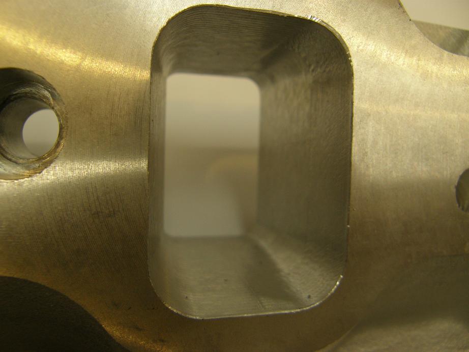
Here's some photos of the one that came off the machine last night. This is the third manifold that I've tried; the first two have machining errors that make them unusable on an engine. Here's a shot inside one of the CNC ports, which really took me quite a bit longer to program than I had anticipated.
I did discover one problem with the ports along the way. The position of the pattern for the cast port for cylinder 7 is off just a little bit; here's a pic of that port, where you can see the upper left corner is still as cast, rather than machined:
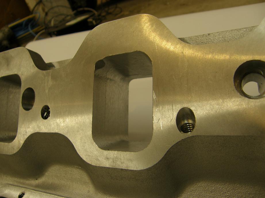
In the immortal words of Maxwell Smart, "Missed it by THAT much!" Fortunately the port cores are about the simplest part of all the core parts, and I can get that core box modified before I cast the first production run of manifolds. In order to test a new core, I've taken some of the sand cores that the foundry gave me and modified them by sanding away that upper left corner. I'm going to get another two or three manifolds cast with these modified cores to make sure that they will fix the problem, and then I'll have the core box modified to reflect the change.
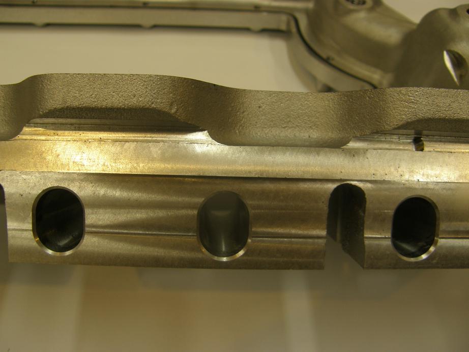
I've been really struggling the last few weeks over the pushrod holes. I wanted to make them work for low riser and medium riser pushrod spacings (2.0" and 2.10", respectively), but still leave a decent wall between the pushrod hole and the port so that people who are port matching don't inadvertently go through into the pushrod hole. I talked to Barry R and Blair P about this issue; I wanted to go with an oblong hole, but this would make it more difficult to sleeve the hole if you did happen to break through when porting. A round hole, of course, would be much easier to sleeve. Now in the past, I've actually done some sleeving with oblong tubes; in fact I built a special arbor a while back that would allow me to take an aluminum tube, squash it in the vise a little, and push it onto the arbor, which was an oblong shape. Then I was able to sleeve the oblong hole (that I had previously machined) in the manifold I was working on; I think it was the Victor I used in my Mach 1 back in 2005. You just tap the arbor in place with the pushrod tube installed on it, along with some JB Weld or Loctite or whatever, and the knock the arbor out from the other side. Anyway, the better fit to the pushrods with varying valve spacing that you get with the oblong pushrod hole won out; maybe I'll end up making an oblong arbor available for anyone who needs to sleeve these holes. And of course I plan to offer the pushrod holes in different locations for anyone who is running an offset rocker arm. So, maybe having to sleeve an oblong hole won't come up very much. Here's a photo of a few of the pushrod holes in the intake:
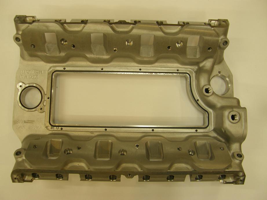
One good idea that came up on this forum a while back was to O-ring the road draft tube hole. I was already planning on O-ringing the center access panel hole, and had thought briefly about O-ringing the road draft tube hole too, but didn't really pursue that idea because I was concerned that the basket that fits into the road draft hole opening was too big to allow a decent O-ring, and still leave enough material to seal with a regular gasket outside the O-ring if necessary. But after it came up here I decided to look at this again, and it turned out that there was barely enough room if I used a 3.375" OD O-ring. So this manifold has been machined for one, and it looks like it will work out pretty well. Here's a pic of the manifold from the top, showing both O-rings in position:
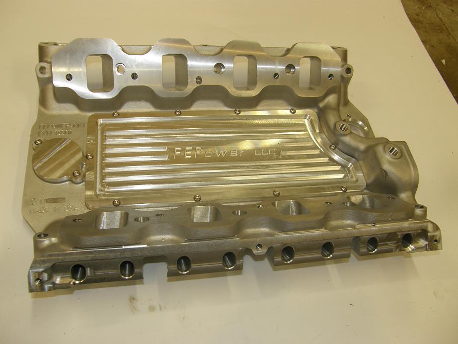
Finally here's another pic of this manifold with the covers installed. I ended up using button head capscrews on the covers because in one case, the 351C manifold interfered with the taller heads of the regular allen head capscrews. It's always something; thankfully the button heads solved the problem:
The only thing I really have left to do, assuming the next manifold comes out of the machine looking good, is to build a fixture to drill and tap the thermostat housing holes and the water bypass tube hole. I should be able to get that done next weekend; then it will be time for the dyno...


