It was the sender!!
Just kidding

I got it figured out. First, I want to thank everybody for trying to help me. Sometimes electrical issues can just be hard to isolate when multiple systems are involved in 40+ year old wiring. And the '69 and later cars are just more prone to problems when they got away from hard wiring circuits.
I did get it working. I had to go to Detroit Thursday and in between dodging Michigan potholes and dodging cars in roundabouts, the drive up and back gave me time to think about it. I was making it harder than it needed to be by second-guessing my findings. A couple notes....
1: Getting continuity and making the gauges work by running the batteries through the cluster chassis was merely a result of back-feeding through the regulator. I thought that may have been the case, but second guessed my findings. The Constant Voltage Regulator schematic clearly shows the connection to ground for the internal heater. That connection also allows voltage to flow back and into the regulator and through the internal switch and onward to the gauges. I should have just went with what I knew and saw but I made it much more difficult by second guessing myself. I realized this when I had some time to think about it.
2: After checking every connection, wire, gauge and ground I knew that left only a couple of options. The old Sherlock Holmes quote definitely applies here..."when you have eliminated the impossible, whatever remains, however improbable, must be the truth". There were only 2 possibilities left. 1, the resistor feed wire was going bad and losing its ability to hold a load, or 2, the ONLY connection that I could not physically check while hooked up was faulty.....the main harness connector to the cluster.
I decided to physically jumper from the harness to each gauge. So I set the cluster in the middle and jumpered from the correct lead on the main harness connector to the gauge POWER feed connection on the PCB. That way it was going through the regulator as it's designed to do. Then I grounded each gauge individually.
Heres a couple shots of how I did that.

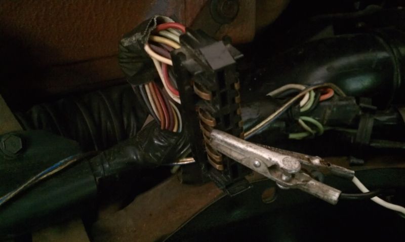
I was careful so that each jumper wire did not touch any other connector lead. And each one worked! YAY!!
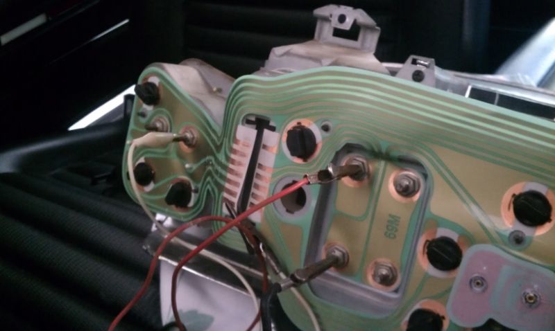
So then I ran a jumper from every gauge to ground simultaneously to see if the main harness' resistor feed wire would hold the load of all 3 gauges working at their highest reading. That places the highest load on the resistor wire feed and regulator that it would see in the real world. A bit of a warning here, you wouldn't want to hold them all straight to ground for any extended period or you run the risk of burning out the windings in the gauge, but a short grounding of each gauges feed wire at the sensor or sender will tell you if they are working properly. Heres a shot of my jumper wires on the back going to ground and the feed wire hooking to the PCB.
They all worked!! DOUBLE yay!!
So it HAD to be the main connector to the PCB. I was careful to clean both sides of the connections with polishing paper and made sure none of the connectors spring "tangs" were flattened. I even checked to make sure of imprinting on the PCB connections to make sure there was contact, which I showed a picture of earlier. But as it turns out, when I inspected them very closely, the imprints were a little faint on a few of the PCBs connectors. So I polished everything again and pried out slightly on all the main harness' connector tangs, making sure they had a good arch and spring to them. Then I made sure the PCB was centered perfectly on the housing and plugged in the main harness.....hit the key...and here was the result....
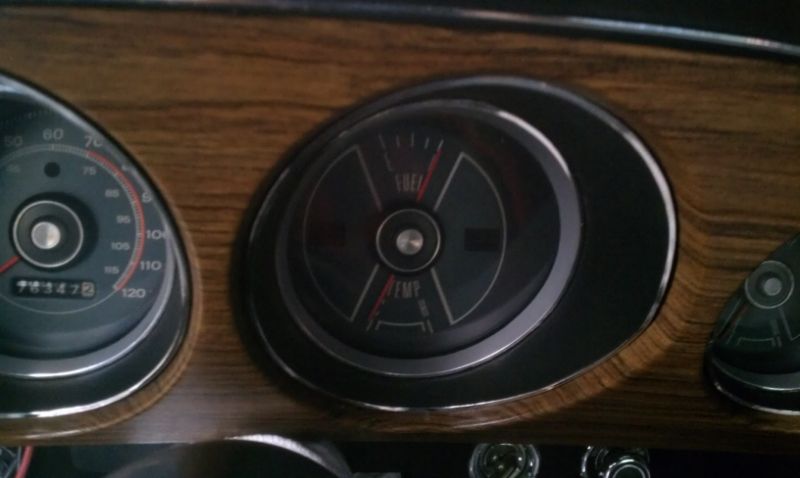
So just to make sure my sender was good, I pulled the ground off of my tank sender wire, hooked it back up to the sending unit on the tank....and here was the result....
Notice anything familiar? And yes, it does have a full tank of fuel

So I spent the next hour watching the fuel gauge as I jostled, shook and generally beat on the dash unit trying to simulate scared passengers shaking in the car
It still worked. So I put everything back together finally. DONE!!
I have to say though, I think this winter or early next year I'm going to rid myself of that PCB and hardwire my cluster like the older cars were. '69 was the first year for the PCBs and they are a pain. You just don't have those problems with the earlier cars with individual wiring to each spot.
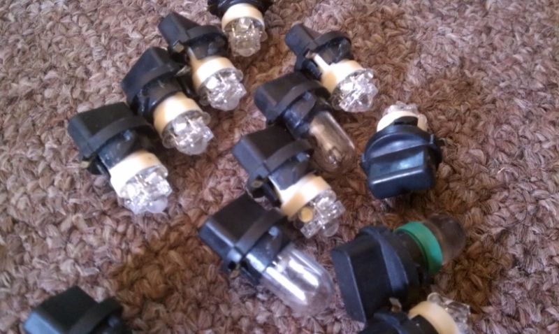
One last thing. Anybody with a '69-'73 Mustang knows how dim the dash lights are and how hard they are to see at night. I took the opportunity to try out an LED dash light kit, but only on my main clusters dash lights. Not the clock or the turn signals or anything else, because they are bright enough. I have to say, they made a BIG difference! They are MUCH easier to see, keep the same hue as the original lights, and aren't too bright as to overpower the overall look of the cluster. I really like them, although I had to fiddle quite a bit with the wires on the LEDs to make them get good contact, I really like them as an upgrade in the dash.