Author Topic: Fuel gauge not working on my '69 Mach....  (Read 33997 times)

0 Members and 1 Guest are viewing this topic.

cjshaker

  • Hero Member
  • *****
  • Posts: 4474
    • View Profile
Re: Fuel gauge not working on my '69 Mach....
« Reply #15 on: June 04, 2014, 11:39:34 AM »
Same question as My427stang, "What happens if you ground the sender wire?  Does it go full?"
If it does go full then I would say it is the sending unit.
If you want a further test ground the sender wire through a variable resistor and watch the gauge go up and down.
I believe ScotiaFE is correct, it is going to be the sending unit.

That was the very first test I did. I mentioned it in my first post, but it was kind of long so I think you guys just missed it. The gauge did not move when grounded. And when performing Lous' suggested test, I could not even get the light to come on. So I am positive that the sender is not my issue.
« Last Edit: June 04, 2014, 12:21:09 PM by cjshaker »
Doug Smith


'69 R-code Mach 1, 427 MR, 2x4, Jerico, 4.30 Locker
'70 F-350 390
'55 Ford Customline 2dr
'37 Ford Coupe

jmlay

  • Full Member
  • ***
  • Posts: 199
    • View Profile
Re: Fuel gauge not working on my '69 Mach....
« Reply #16 on: June 04, 2014, 12:42:17 PM »
This is a great suggestions, "If you want a further test ground the sender wire through a variable resistor and watch the gauge go up and down". Or you could just get a few resistors & test with those in place of sender. Sounds like there is an open in the circuit/wiring between the gauge & the trunk. Run a new wire from the sender to the gauge, if all works you just need to find your open.
Mike

cjshaker

  • Hero Member
  • *****
  • Posts: 4474
    • View Profile
Re: Fuel gauge not working on my '69 Mach....
« Reply #17 on: June 04, 2014, 02:54:12 PM »
This is a great suggestions, "If you want a further test ground the sender wire through a variable resistor and watch the gauge go up and down". Or you could just get a few resistors & test with those in place of sender. Sounds like there is an open in the circuit/wiring between the gauge & the trunk. Run a new wire from the sender to the gauge, if all works you just need to find your open.

As I said before, I tested the wire from the sender clear up to the cluster plug-in. It is good. I even tried running a jumper wire from the wire off the plug-in to ground to eliminate that entire harness to the tank. Still nothing. Using a variable resistor in the senders wire would not be any different than trying it to ground. If the gauge will not move with it grounded, then it won't move with any resistor in the line.

I do know a little about electronics, although when I get frustrated I tend to forget the simple things. Like when Ohms Law was mentioned from Jay. I used to work on kitchen cooking equipment which had plenty of electronics, and I tinker with working on my own tube amplifiers, but I am no expert by any means.

At this point I'm thinking the resistor wire feeding the gauge cluster is faulty, but I was hoping somebody could confirm/disprove my thinking on the regulator terminal/ground readings I got. The regulators schematic seems to suggest (to me) that it basically works like an alternator regulator, but on a much simpler level. I just don't know enough about the electronics involved as to whether or not it is a physical connection to ground inside the regulator which would explain my ground readings and why the gauges work when powering through the clusters housing.

I tried disconnecting the regulator at the posts and the gauges do not read when powered through the housing. That confirms that power is traveling through the regulators housing, feeding the gauges. I think I need to rig up a 10 ohm resistor wire and feed it to the cluster while hooked up to the main harness and see if the gauges work then.

Edit: I'm having my Dad bring down some wire-wound 10 ohm resistors to rig up a feed for it. I'm not sure if carbon resistors will handle the load. He went to DeVry University in the '50s for electronics. Actually made my Grandpa and Grandmas first TV and had his own TV and Radio shop when he was young. He's got tons of old electronic equipment, but at 84 he's gotten kinda bad at remembering some stuff. It's not good that I have that same problem at my age ::)
« Last Edit: June 04, 2014, 03:14:10 PM by cjshaker »
Doug Smith


'69 R-code Mach 1, 427 MR, 2x4, Jerico, 4.30 Locker
'70 F-350 390
'55 Ford Customline 2dr
'37 Ford Coupe

jayb

  • Administrator
  • Hero Member
  • *****
  • Posts: 7436
    • View Profile
    • FE Power
Re: Fuel gauge not working on my '69 Mach....
« Reply #18 on: June 04, 2014, 03:53:10 PM »

At this point I figured the resistor wire feeding the gauge cluster was bad. But before I condemned it, I played around with the gauges some more to see if I had a short somewhere causing the voltage drop from the resistor wire as Jay suggested might be the case. This is where I got confused again. I got a continuity reading from grounding to the metal cluster housing, then to each terminal on every gauge. This, to me, indicated I had a short somewhere and that that would cause the voltage drop from the resistor wire.


Next, I checked for continuity from the regulator to the cluster housing. First from the regulator housing to the cluster housing. I got good continuity as I should have. Then I checked on the primary and secondary side of the regulators terminals to the cluster housing. I got 12.78 ohms on the secondary side....then 4.27 ohms (yeah, ironic huh :) ) on the PRIMARY side. I thought BINGO, I have a short in the regulator! It shouldn't be reading from the regulator terminals to ground.


As you can see, the primary and secondary sides of the regulator seem to be connected to the regulator housing, or ground. So the numbers I got appear to be normal. This also explains why everything worked fine when I powered through the regulator.

So now I am wondering why and how this works. When I jumper the positive side of my batteries to the cluster HOUSING, then connect the negative to the secondary side of the gauges, they work. This just doesn't seem right to me ??? But I am not an electrical engineer, so I may just be wrong. Am I simply feeding power through the ground, into and through the regulator (essentially bypassing it) and on to the gauges? According to the schematic, that seems to be the case.

IF this is normal, then my issue is with the resistor wire feeding the cluster. So now I need an engineer to tell me if this is normal per the schematic.
Is there a Doctor in the house? :)


Just so that we are using the same terms, when you say the primary side of the regulator, you mean the input side, right?  The side that gets the 12V through the resistor wire?  Then by secondary you mean the output side, where the gauges get 5V?

The regulator is connected to the gauges, and the gauges are a resistive load.  When you check continuity, you are talking about checking resistance in Ohms, so from the output of the regulator you have several resistive loads (the gauges) in parallel, running to ground.  So, you should get some resistance level when you make that check, and 12 Ohms is certainly not out of the question.

The fact that you are getting a lower resistance from the input side of the regulator to the ground is kind of confusing, but may be possible depending on the design of the voltage regulator.  However, if you are powering up the steel housing of the gauge panel with 12V, grounding the gauges, and they work, I think there has to be a short somewhere.  Ford wouldn't have powered up the steel housing of the gauge panel.

One other thing that dawned on me was the connector.  If I recally correctly '69s have a pretty marginal connector to the circuit board, don't they?  I seem to recall that the connector wasn't indexed in place real well, and it might be possible to move it around and potentially short two of the traces on the circuit together.  Maybe a ground and an input power?  Sure wish I was there to look at this for you, Doug...


Jay Brown
- 1969 Mach 1, Drag Week 2005 Winner NA/BB, 511" FE (10.60s @ 129); Drag Week 2007 Runner-Up PA/BB, 490" Supercharged FE (9.35 @ 151)
- 1964 Ford Galaxie, Drag Week 2009 Winner Modified NA (9.50s @ 143), 585" SOHC
- 1969 Shelby Clone, Drag Week 2015 Winner Modified NA (Average 8.98 @ 149), 585" SOHC


cjshaker

  • Hero Member
  • *****
  • Posts: 4474
    • View Profile
Re: Fuel gauge not working on my '69 Mach....
« Reply #19 on: June 04, 2014, 04:50:23 PM »
Just so that we are using the same terms, when you say the primary side of the regulator, you mean the input side, right?  The side that gets the 12V through the resistor wire?  Then by secondary you mean the output side, where the gauges get 5V?

The regulator is connected to the gauges, and the gauges are a resistive load.  When you check continuity, you are talking about checking resistance in Ohms, so from the output of the regulator you have several resistive loads (the gauges) in parallel, running to ground.  So, you should get some resistance level when you make that check, and 12 Ohms is certainly not out of the question.

The fact that you are getting a lower resistance from the input side of the regulator to the ground is kind of confusing, but may be possible depending on the design of the voltage regulator.  However, if you are powering up the steel housing of the gauge panel with 12V, grounding the gauges, and they work, I think there has to be a short somewhere.  Ford wouldn't have powered up the steel housing of the gauge panel.

One other thing that dawned on me was the connector.  If I recally correctly '69s have a pretty marginal connector to the circuit board, don't they?  I seem to recall that the connector wasn't indexed in place real well, and it might be possible to move it around and potentially short two of the traces on the circuit together.  Maybe a ground and an input power?  Sure wish I was there to look at this for you, Doug...

Yes, I should be saying the "hot" or "input" side and "load" side referring to the regulator terminals. Wrong terminology can confuse things for sure.

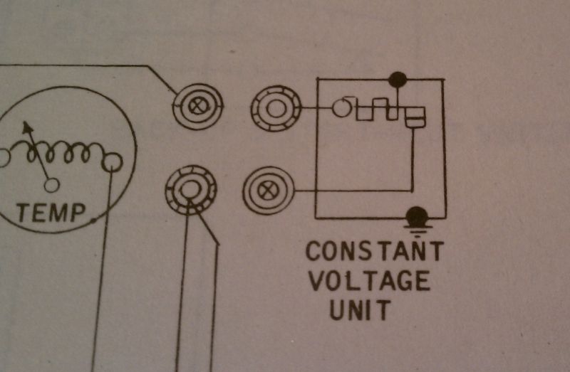
I added a picture of the regulator in the schematic. Not sure if you saw it or not, but it shows the connections to the regulators housing, which is grounded through the PCB. The connections to the housing are not only on the load side, but also the input side. According to the books symbol chart, this is a thermal switch that regulates the voltage. Much like the alternator regulator.

The regulators schematic....


Symbol chart....


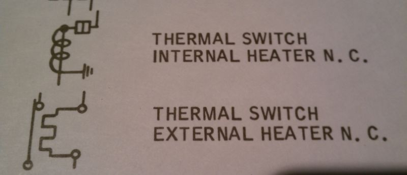
As you can see, there is some variance from the books symbols to the actual regulators schematic. The symbol shows it being an external heater where the schematic shows an internal type, but with external "graphics". Not sure if it uses a bi-metal switch or some other type. Being DC it can't be based on cycles.

I certainly wouldn't think the housing would be "live" either, but the heater seems as though it could back feed when I apply voltage to the housing. And if the switch is closed that would complete the circuit making the gauges powered.

I have inspected the entire set-up six ways from Sunday and can not find where a short could occur or IS occurring....other than through the regulator itself. And according to the schematic, that is by design for the heater.

And to FURTHER complicate things, with every gauge disconnected from the PCB, and with them REMOVED from the cluster, I get a continuity reading from every gauges post to its respective housing. As if every gauge is shorted to its housing. This is just not right, and I can find no trace of why it should be shorted (as I said, each gauge has its internal and external "isolator" pad)....yet I still get continuity.

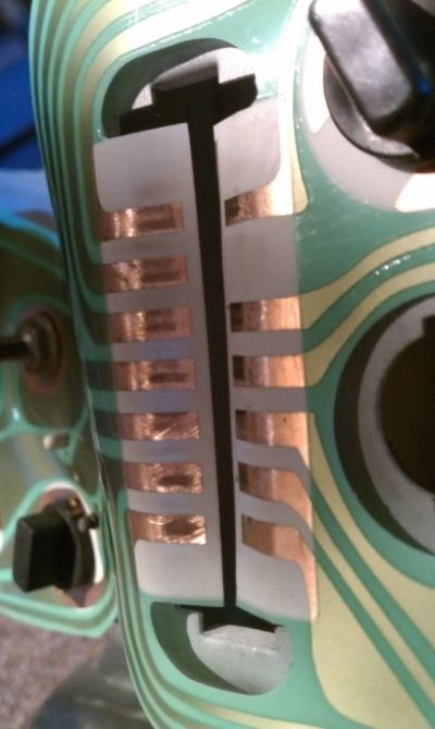
I also thought about the plug-ins indexing, and checked it. You can see in this picture that the connections seem to be squared quite nicely with there respective contact....


When I start looking for the sledgehammer as my next tool.....it's time to walk away and take a break. And that is very much needed right now :-[
Doug Smith


'69 R-code Mach 1, 427 MR, 2x4, Jerico, 4.30 Locker
'70 F-350 390
'55 Ford Customline 2dr
'37 Ford Coupe

bn69stang

  • Hero Member
  • *****
  • Posts: 541
    • View Profile
Re: Fuel gauge not working on my '69 Mach....
« Reply #20 on: June 04, 2014, 04:58:24 PM »
I had the same problem , and started checking things because i was leaning towards a gauge but it ended up being a bad sending unit ..
69 mach 1 , 428 C J  Blue Oval Performance BBM heads -T@D rocker s- Blue thunder intake - Comp hydr roller - MSD ignition - FPA headers- Holley 850 hp double pumper - TKO 600 - 9 inch 3.89 Detroit Locker . ride tech coil over conversion - power rack @ pinoin steering - 13 inch drilled @ slotted 4 wheel disc brakes ..

cjshaker

  • Hero Member
  • *****
  • Posts: 4474
    • View Profile
Re: Fuel gauge not working on my '69 Mach....
« Reply #21 on: June 04, 2014, 05:13:15 PM »
I'm not sure if you guys get the idea that the gauge wont read even when the sending units wire is grounded. The sender does the same thing. It "varies" the grounding that occurs. The more grounding that the sender does, the fuller the gauge should read. One of the first checks to do for a sender is ground the wire itself, if the gauge starts moving then your sender is bad. If the gauge wont read with the wire fully grounded, I fail to see how the sender will make any difference.

But anyway, enough about the sender. It is not the issue.
Doug Smith


'69 R-code Mach 1, 427 MR, 2x4, Jerico, 4.30 Locker
'70 F-350 390
'55 Ford Customline 2dr
'37 Ford Coupe

bn69stang

  • Hero Member
  • *****
  • Posts: 541
    • View Profile
Re: Fuel gauge not working on my '69 Mach....
« Reply #22 on: June 04, 2014, 05:14:17 PM »
Doug go have a cold one , unwind before sledge hammmmmering operation starts ... Bud
69 mach 1 , 428 C J  Blue Oval Performance BBM heads -T@D rocker s- Blue thunder intake - Comp hydr roller - MSD ignition - FPA headers- Holley 850 hp double pumper - TKO 600 - 9 inch 3.89 Detroit Locker . ride tech coil over conversion - power rack @ pinoin steering - 13 inch drilled @ slotted 4 wheel disc brakes ..

cjshaker

  • Hero Member
  • *****
  • Posts: 4474
    • View Profile
Re: Fuel gauge not working on my '69 Mach....
« Reply #23 on: June 04, 2014, 05:21:43 PM »
Doug go have a cold one , unwind before sledge hammmmmering operation starts ... Bud

Now that is advice I can adhere to :)

I did not mean to come across as unappreciative. Just very frustrated right now. Thanks for everyones help.
Doug Smith


'69 R-code Mach 1, 427 MR, 2x4, Jerico, 4.30 Locker
'70 F-350 390
'55 Ford Customline 2dr
'37 Ford Coupe

jayb

  • Administrator
  • Hero Member
  • *****
  • Posts: 7436
    • View Profile
    • FE Power
Re: Fuel gauge not working on my '69 Mach....
« Reply #24 on: June 04, 2014, 11:29:03 PM »
OK, let's assume that the wiring in the dash is all OK.  Seems strange to me that Ford would put voltage on the instrument panel chassis, but maybe I'm missing something there.  One thing that could cause your problem is if the resistor wire went high in resistance.  Then, when the gauges tried to pull current through the resistor wire, the voltage would drop to some very low level.  I think you were seeing something like that with one of your earlier tests.  Measure the resistance from the end of the resistor wire, where it attaches to the panel, and the instrument cluster fuse.  If the resistor is in between there you should see some resistance level, probably only a few ohms.  I think it is a 2 amp fuse for that wire, correct?  So if 2 amps is the maximum current, and you need at least 5V at the regulator to make it work properly, then the resistor should be (12V - 5V)/2 amps, or 3.5 Ohms.  If you measure a resistance much higher than that, then the resistor wire has increased in resistance, and when the instrument panel tries to pull current it is pulling the voltage way down, to far down for the regulator to work.  I think temporarily it would be OK to run a wire directly from the fuse panel to the instrument panel, with no resistor in the wire, to check for correct operation.  Maybe use a 50 foot length of wire so that the resistance of the wire itself is significant.  Once connected, flip on the key and see if your fuel gauge works.

If that's not it, its the sender  ;D ;D ;D
Jay Brown
- 1969 Mach 1, Drag Week 2005 Winner NA/BB, 511" FE (10.60s @ 129); Drag Week 2007 Runner-Up PA/BB, 490" Supercharged FE (9.35 @ 151)
- 1964 Ford Galaxie, Drag Week 2009 Winner Modified NA (9.50s @ 143), 585" SOHC
- 1969 Shelby Clone, Drag Week 2015 Winner Modified NA (Average 8.98 @ 149), 585" SOHC


Lenz

  • Hero Member
  • *****
  • Posts: 578
    • View Profile
Re: Fuel gauge not working on my '69 Mach....
« Reply #25 on: June 05, 2014, 07:55:27 AM »
Doug go have a cold one , unwind before sledge hammmmmering operation starts ... Bud

Now that is advice I can adhere to :)

I did not mean to come across as unappreciative. Just very frustrated right now. Thanks for everyones help.

One thing is certain, with the wealth of information that's been presented in this thread we've got a comprehensive approach to troubleshooting a crabby fuel gage system.  I am one of several I'm sure who are looking forward to hearing the final solution.  I can appreciate the level of frustration at what is seemingly a simple setup >:(.
Len Zielinski
'64 Galaxie 500 445 Toploader
'69 F100 300 stick

bn69stang

  • Hero Member
  • *****
  • Posts: 541
    • View Profile
Re: Fuel gauge not working on my '69 Mach....
« Reply #26 on: June 05, 2014, 05:15:46 PM »
yes the problems that just hang around and frustrate the heck out of you , and this forum does help to sort them out , so from me many thanks to the forum .. Bud
69 mach 1 , 428 C J  Blue Oval Performance BBM heads -T@D rocker s- Blue thunder intake - Comp hydr roller - MSD ignition - FPA headers- Holley 850 hp double pumper - TKO 600 - 9 inch 3.89 Detroit Locker . ride tech coil over conversion - power rack @ pinoin steering - 13 inch drilled @ slotted 4 wheel disc brakes ..

mlcraven

  • Full Member
  • ***
  • Posts: 205
    • View Profile
Re: Fuel gauge not working on my '69 Mach....
« Reply #27 on: June 06, 2014, 06:17:10 PM »
Sheeesh...must be something going around, now my fuel gauge is acting up.  :-[
Michael

Lenz

  • Hero Member
  • *****
  • Posts: 578
    • View Profile
Re: Fuel gauge not working on my '69 Mach....
« Reply #28 on: June 06, 2014, 08:23:18 PM »
Sheeesh...must be something going around, now my fuel gauge is acting up.  :-[
Yeah maybe so ???.  Mine stays right on full until I've got roughly 6 to 7 gallons left in the tank.  Once it starts dropping it drops like a stone to under a quarter of a tank and then sits there and dares me to believe it.  I for my part do not.  I decided it works well enough for now, not sure how things would go on a road trip.  That's why I look forward to seeing what it takes to get Doug's gage to tell him the truth....
Len Zielinski
'64 Galaxie 500 445 Toploader
'69 F100 300 stick

ScotiaFE

  • Hero Member
  • *****
  • Posts: 1409
  • Howie
    • View Profile
Re: Fuel gauge not working on my '69 Mach....
« Reply #29 on: June 07, 2014, 05:54:36 AM »
For Lenz and mlcraven.
An inexpensive and easy test is get a sending unit and plug it in. Non Mustang units always cost more, but most Mustang units
will fit and do the job. Hope this helps.

https://www.mustangsunlimited.com/itemdy01.asp?T1=9275B+01&Category=Air%2FFuel&subCategory=Fuel+Related&SubSubCategory=Fuel+Sending+Units&CatKey=EMUSTANG