Jay and Doug i have copies of the Ford wiring manual , they cover 69 mustang and cougar .
Bud, I have a factory Ford wiring and vacuum book that covers all Ford products for 1969. Picked it up many years ago for $5 at a local yard sale of all places. It turned out to be very valuable when I restored my car. Here's a couple shots of it...
First, I did as Lou suggested and did the test light test. The light never even hinted at coming on.
Next, I double checked continuity from the plug-in back by the tank up to the cluster plug-in. I got about 3 ohms which seems like a good number considering the footage of wire involved. I checked each connection point (there are 2, a 3 prong plug behind the dash and the single connection in the trunk for the sender wire), visually and by wiggling it to make sure there was no intermittent connection failure.
So I did Jays suggestion next and used 3 D batteries and powered up my gauge cluster. A shot of the battery set-up, minus the leads I used to jumper to the gauges....
Doing this, I got every gauge to work perfectly. First I went across each terminal on the respective gauges. They all moved nice and smooth with no hesitations. Second, I went to the primary side of the regulator on the circuit board then to the secondary side of each gauge. Again, they all worked smoothly. That told me that the circuit board and the regulator seemed to be working fine and was making good connection at all points.
At this point I figured the resistor wire feeding the gauge cluster was bad. But before I condemned it, I played around with the gauges some more to see if I had a short somewhere causing the voltage drop from the resistor wire as Jay suggested might be the case. This is where I got confused again. I got a continuity reading from grounding to the metal cluster housing, then to each terminal on every gauge. This, to me, indicated I had a short somewhere and that that would cause the voltage drop from the resistor wire.
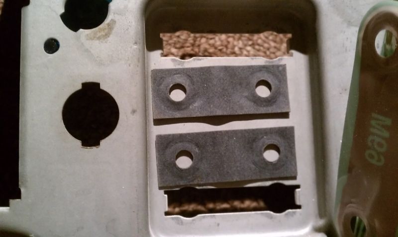
I took all my gauges out and inspected them. All isolating pads are in place as they should be, and in good shape. I even checked to make sure they did not give a continuity reading through the isolation pads. A shot of the pads on the back of the gauges, and the ones that go on the outside of the cluster to isolate it from the housing....
This one just showing the pads without the gauges being installed....
Next, I checked for continuity from the regulator to the cluster housing. First from the regulator housing to the cluster housing. I got good continuity as I should have. Then I checked on the primary and secondary side of the regulators terminals to the cluster housing. I got 12.78 ohms on the secondary side....then 4.27 ohms (yeah, ironic huh

) on the PRIMARY side. I thought BINGO, I have a short in the regulator! It shouldn't be reading from the regulator terminals to ground.
WRONG. I checked the schematic.....
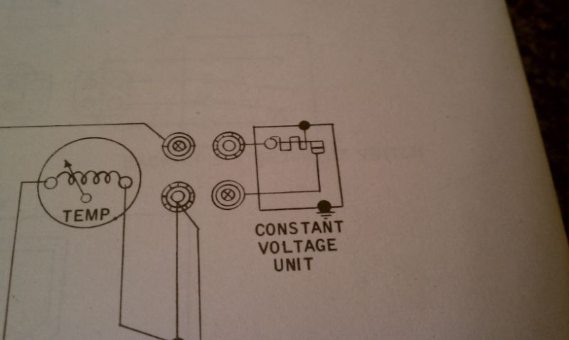
As you can see, the primary and secondary sides of the regulator seem to be connected to the regulator housing, or ground. So the numbers I got appear to be normal. This also explains why everything worked fine when I powered through the regulator.
So now I am wondering why and how this works. When I jumper the positive side of my batteries to the cluster HOUSING, then connect the negative to the secondary side of the gauges, they work. This just doesn't seem right to me

But I am not an electrical engineer, so I may just be wrong. Am I simply feeding power through the ground, into and through the regulator (essentially bypassing it) and on to the gauges? According to the schematic, that seems to be the case.
IF this is normal, then my issue is with the resistor wire feeding the cluster. So now I need an engineer to tell me if this is normal per the schematic.
Is there a Doctor in the house?


