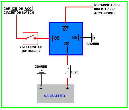
Fount this diagram online.
My thought was:
Pin 30 - will be 12V(+) constant from battery
Pin 87- Trigger wire (+) to starter Solenoid
Pin 85- Constant Ground (-) so we don't have to worry about the PCM/ PATS supplying it.
Pin 86- 12V(+) from push button start switch.
Then on the push button start......
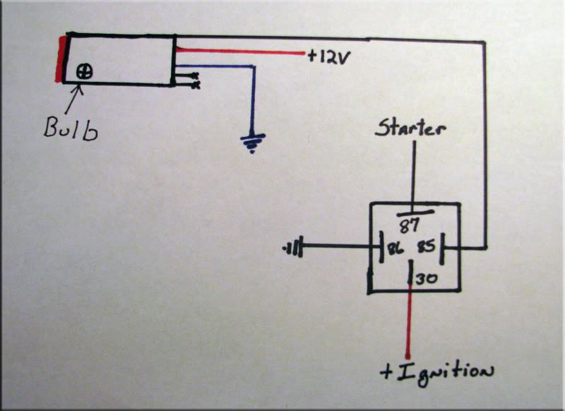
- Top wire on the Push Button Start goes to pin 86 (the person who made this sketch swapped their pin locations)
- Second wire will get 12V(+) from a "Hot in Run" wire so the key actually has to be turned to run and fuel pumps running before you can push the button to start.
- Third wire will be a ground wire for the switch.
- 2 separate wires in the diagram I am guessing are power and ground for the bulb to make the switch light up .
Does this seem right? I have to stress I hate wiring, but at least this way I don't have to worry about anti theft or Powertrain control module telling the car not to start.


