I continued to make progress this week on the high riser, with more CNC work on the intake manifold setup. I had a few setbacks but they were CNC machine related. First, earlier this week the coolant pump suddenly stopped working. This happened while I was around the corner from the machine, working on something else, and by the time I head the tool start making screeching noises it was too late to save the end mill in the machine at the time, or the valve cover rail spacer that I was machining. I got up and running again by picking up a sump pump from Menards and Mickey-mousing the thing together so that I had coolant again, but this basically took out a couple evenings this week. My replacement coolant pump has now arrived, so sometime over the weekend I'm going to have to install it.
Then, today when I was machining the valley cover plate for the intake, the machine suddenly stopped, flashing an 'X-axis error' on the computer screen. Wisps of smoke started coming from under the table, and I quickly shut the machine off. After getting everything cleared away so I could see what was going on, I found a broken conduit and a broken wire. The wiring that goes to the servo motor and encoder on the X-axis runs inside a flexible conduit. This conduit had broken about 6" under the table, and the ends had separated, exposing the wires. One of the wires had been cut, probably by the sharp end of the conduit. Once I figured this out, it was a simple matter of reconnecting the wire by soldering a short piece in, and then wrapping the whole thing up in electrical tape to protect the wire bundle from the broken edges of the conduit. Then I used a piece of heater hose, sliced down the length, to cover up the break in the flexible conduit, and duct taped over the whole thing. This is admittedly another Mickey Mouse repair; I really should take the whole thing apart and put a brand new piece of conduit it. But I have no idea how much work that would be; the wires disappear into the servo motor box and I don't know if they would be easily disconnected, or what other problems I may run into trying to do this. So, I'm going to live with the repair I've made for now.
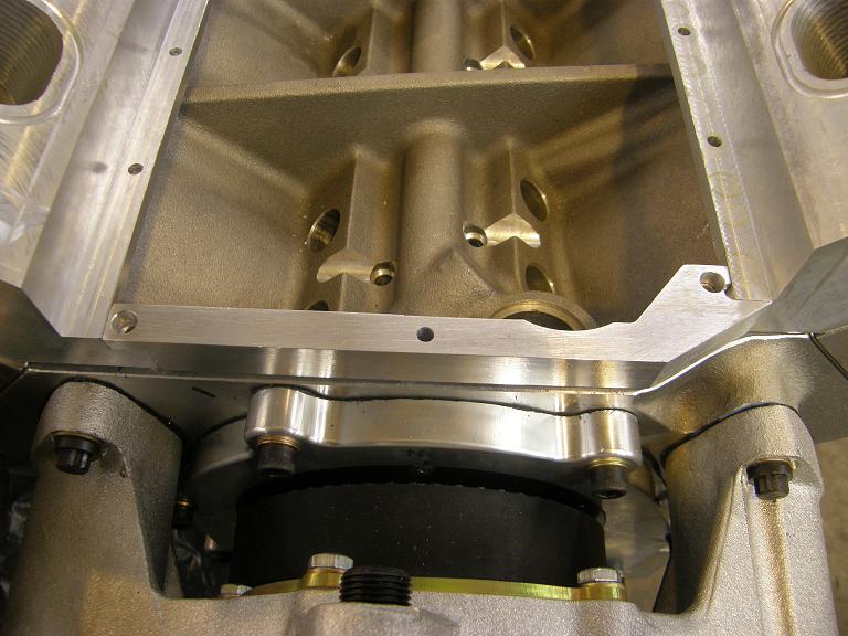
I burned up three hours on that repair, but finally got the remaining work on the manifold base completed. Here's a picture of the valley cover plate being drilled for the holes to bolt it to the port plates. This is also prior to any of the "dress-up" machining that I did on the plate:

Here are some photos showing the manifold end rails, the valve cover spacers, and the completed valley cover plate:


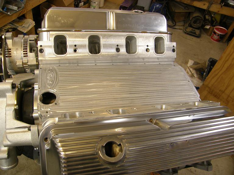

I really like the way the valley cover plate turned out. I machined the fins in the plate with a 1/8" 10 degree taper end mill, and spaced them so that they are the same as the fins on the valve cover. The covers look nice polished, so I'm thinking about getting the valley cover plate polished too. The Ford logo came to me courtesy of a local friend who owns and operates a tool and die shop. He sent me the G-code, and I just had to make a couple of minor code modifications to make it run on my machine. The logo is .010" deep, and was cut with a 1/16" ball end mill. I practiced on a couple of scrap pieces before I did this, and managed to break one of those tiny little mills before I got the feeds and speeds right. But in the end it turned out really nicely, and I think it will add a lot to the engine's appearance, especially since there is no distributor to get in the way of the view of the logo.
Next up is starting to machine the upper portion of the intake, but before I do that I have a couple of programs that Mario sent me to try out on the SOHC rocker arm project. Hopefully I'll post some successful photos of that project tomorrow night.


