Back before the cammer bug bit me in 2007, I was in the process of collecting the parts and getting the machining operations done for an FE high riser project. This engine used a Shelby block, Blue Thunder high riser heads that were max effort ported, and one of two potential intake manifolds: a tunnel wedge intake for the high riser, and a sheet metal intake.
For the sheet metal intake I started with a Dove tunnel wedge manifold, and cut the top off so I could weld on sheet metal runners. At the time, this seemed a lot easier than trying to machine the plates necessary for the ports of the intake, with all the pushrod holes, the bottom plate connecting the two port plates together, etc. At the time I only had a cheap Chinese copy of a Bridgeport in the shop, so I went ahead with modifying the Dove intake. I quickly discovered the limitations of my 180 amp TIG welder, as it would constantly blow the breaker as I was attempting to weld the runners to the base. I also found out the hard way that the base would warp severely due to the welding, and in order to get a good seal I ended up welding donuts around each port and machining the base in my mill to correct for the warpage. Finally I got all done with this and leak checked the intake. I found that all my welds were pretty good, but the Dove manifold base leaked like a sieve around the ports and into nearly all of the pushrod holes when the ports were pressurized. Thorougly disgusted with the whole thing, I set the manifold on the shelf and got started on my first SOHC engine.
So here it is, four years later. Things have changed. My TIG welder has been sold, and I've upgraded to a 250 amp unit, with both Argon and Helium available to optimize aluminum welding. I've also acquired a powder coating oven, which makes a great pre-heat oven for welding aluminum parts. My Chinese vertical mill has been replaced by a Bridgeport, I've acquired a CNC machine. And, I have a couple of SOHC sheet metal intake builds under my belt (although I still haven't got one optimized for performance). After Drag Week was over my shop was a complete disaster, so first thing on the agenda was to get the place cleaned up. As I started organizing the shop, I was drawn to the high riser stuff. In addition to all the parts I had acquired before, I had also made a deal a couple years back with Barry R that netted me a Danny Bee belt drive for the cam. Sure would be fun to start playing with all those toys again...
My Galaxie has been sitting engine-less for over a year, and I have a 510" SOHC that I was planning on putting together to go back into that car. I had looked at this engine at the runup to Drag Week, and determined that it really needed pistons and boring before I put it back together. Last weekend I tore down the short block on that engine, and on Monday this week took the block into my shop for the machine work. Ordering the pistons was going to take around 6 weeks, and I didn't feel any pressing need to get the 585" SOHC out of my Shelby clone yet. So, I decided I should put the parts on the shelf to use, and put the high riser engine together.
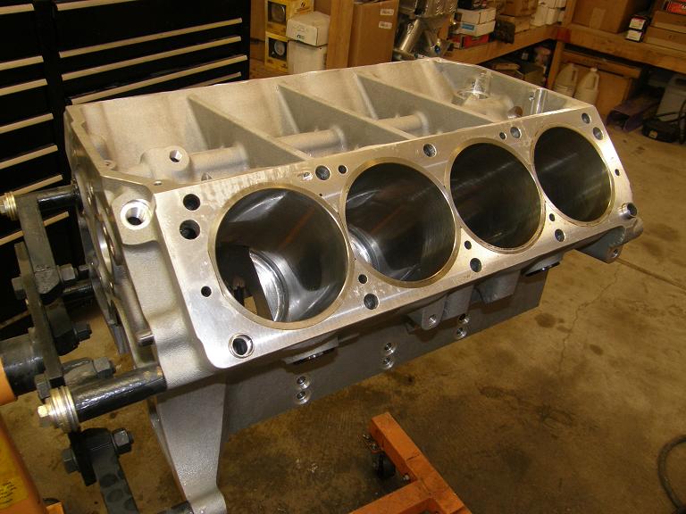
After doing an inventory of the parts, I cleaned up the block and got ready for assembly. Here's a photo of the block ready to go:
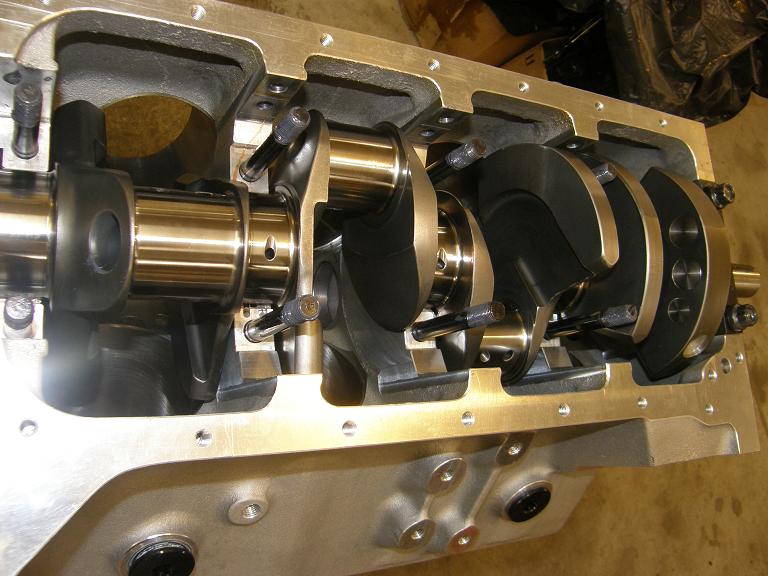
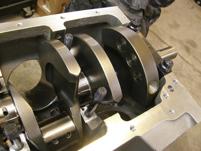
Next I cleaned up and installed the crank. This is a 4.500" stroke Scat crank that has been seriously lightened, with scalloped counterweights. For comparison purposes, the 4.600" stroke crank in my 585" SOHC weighs 67 pounds, while this crank only weighs 51 pounds! Here's some photos of the crank installed in the block, showing the extra counterweight machining:
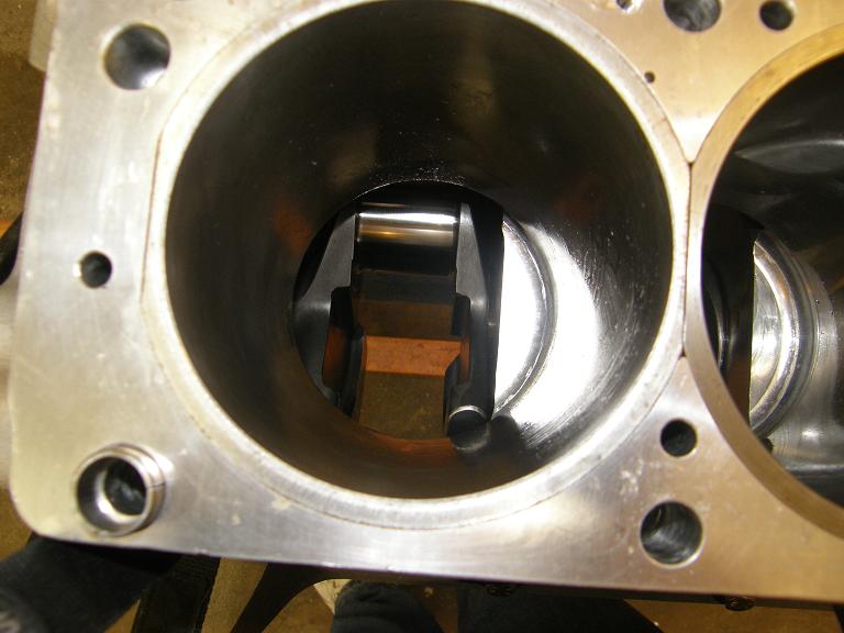
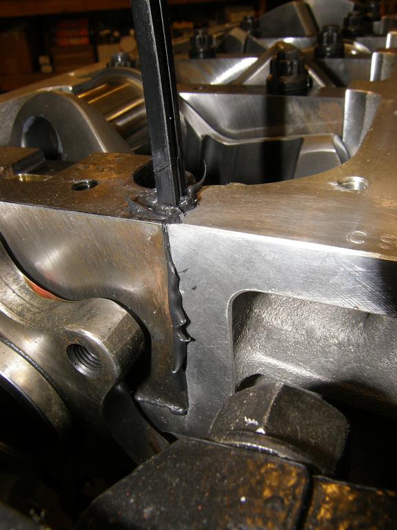
When installing the side seals in the number 5 main cap, I used a different method this time than I normally use. In most cases I coat the side seals with The Right Stuff and install them the normal way with the nails, but this time I decided to try using just sealer, and leave the side seals out. When doing this, you can actually use the rubber side seals to force the sealer down into the seal cavity, to ensure that there are no air pockets. You can tell you are having success when the sealer starts to come out between the #5 cap and the side of the block. Here's a photo showing this:
Here's a photo of the pistons and rods that I have for this engine. The rods are Crower billet rods with BBC rod journal sizes (to match the crank), and 6.700" length. The pistons are 12:1 Diamonds, coated on the top and sides, and use the BBC .990" pin:
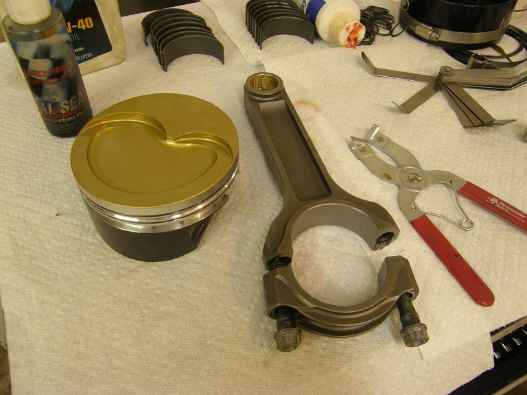
If you look closely at the connecting rod shoulder, you can see that the near shoulder in the photograph has been ground a little for clearance. Since this is not an SOHC engine, there is the potential for interference between the rods and the cam lobes. When I first dummied this engine together, rotating it through led to interference between the rod shoulder and a couple of the lobes on the cam. As a result all the rods had to be ground a little, to keep them all the same weight, despite the fact that only two of the rods interfered with their associated cam lobes.
One thing I kind of regret about this engine is the piston design. When I first ordered these pistons back in 2006, I was not yet pushing the compression ratio as far as I normally do now with my street engines. I was also not moving to a really small ring package. These pistons, at 12:1, leave a little something on the table with respect to compression; especially with the good chamber in the Blue Thunder heads, and with the cam that I selected for this engine, I think I could have gone to 13:1 and still run around town on pump gas. Also, the 1/16" - 1/16" - 3/16" ring package is standard tension and size, and that again is going to leave some power on the table for this engine. I thought briefly about re-ordering the pistons, and going to the higher compression and a set of lower tension .043" - .043" - 3mm rings, but if I did that I'd have the SOHC stuff here by the time I got the new pistons, so I just decided to put it together with the parts I have. I'm shooting for 800-850 HP with this engine, and I should be able to get there despite the 25-35 HP I'm leaving on the table with the pistons I've got.
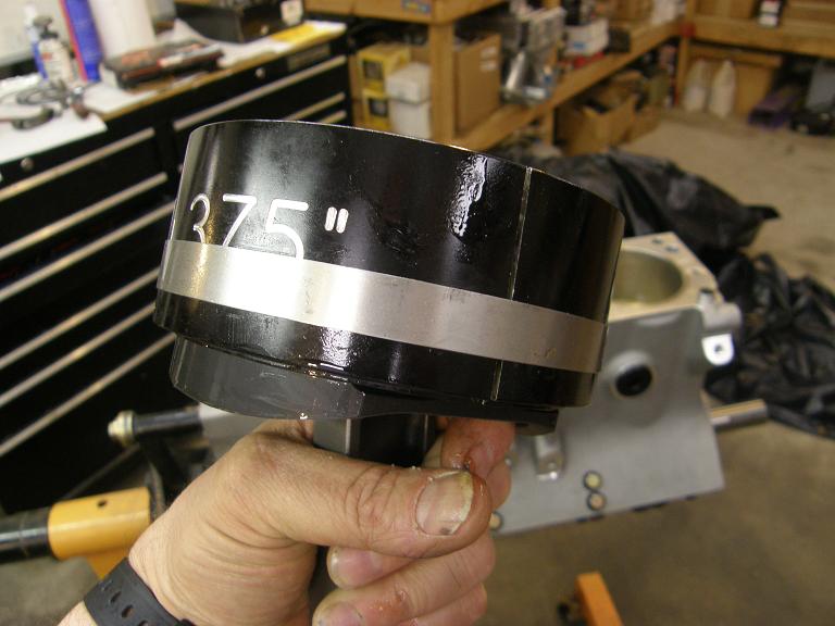
The bore on this engine is 4.375", and I happen to have a tapered ring compressor for this bore size, so the short block went together pretty easily. I also recently acquired a motorized piston ring grinder, with a dial indicator to determine how much material was taken off the rings during the operation. Using this tool was a lot easier than the standard file-fit ring practice I've been using up to now, which involves a hand-cranked rotary file and holding the ring in place by hand. Assembly was fast using these tools. Here's a photo of a piston and rod assembly installed in the tapered ring compressor, and ready for installation in the block:
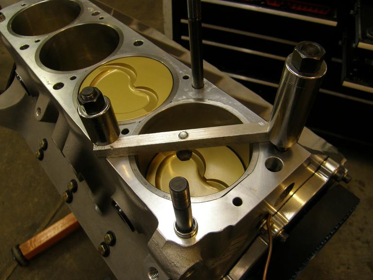
And here's a photo of the pistons installed in the block:

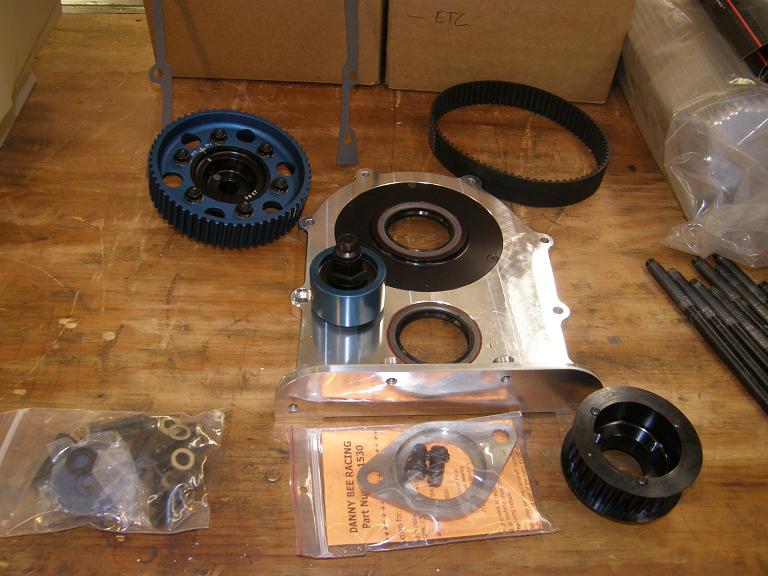
I was able to get all this work done in the evenings this week. I had limited time over the weekend, but I decided to take the time I had and work on getting the Danny Bee belt drive installed. This turned out to be a somewhat arduous task, and thank goodness for my lathe because without it I would have been stuck, but in the end I got the belt drive installed. Here's a photo of all the belt drive pieces as they come out of the box:
After reading the instructions the first thing I wanted to do was to test fit the pullies on the crank and cam. The cam pulley fit on the front of the cam with no trouble, but the crank pulley did not fit on the crank snout. I took some measurements and found that the ID of the crank pulley was nearly 3 thousandths smaller than the crank snout. The instructions said to take some 600 grit sandpaper and sand the crank snout down if the pulley didn't fit; what a joke! No chance of that happening in any reasonable time frame. Instead I chucked the pulley up in my lathe and very carefully took some material off the inside diameter until it was a snug fit over the crank snout. However, when I pushed it on all the say, I encountered another problem; see the photo below:
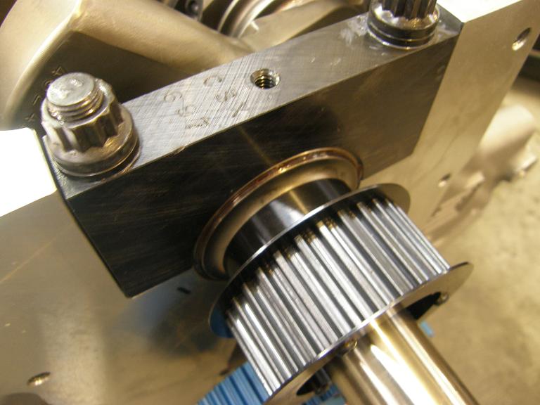
The pulley would not fit all the way up against the flange of the crank; the seal surface was too long, and hit the flange before the body of the pulley bottomed against the crank. Back to the lathe, I cut .080" off the end of the seal surface, and was then able to get the crank pulley slide properly into position. After the successful test fit I pulled the pulley off the crank, and installed the two half moon keyways required by this crank. These are Chivverlay pieces, but it is what Scat puts in all of their cranks, so that's what I had to use.
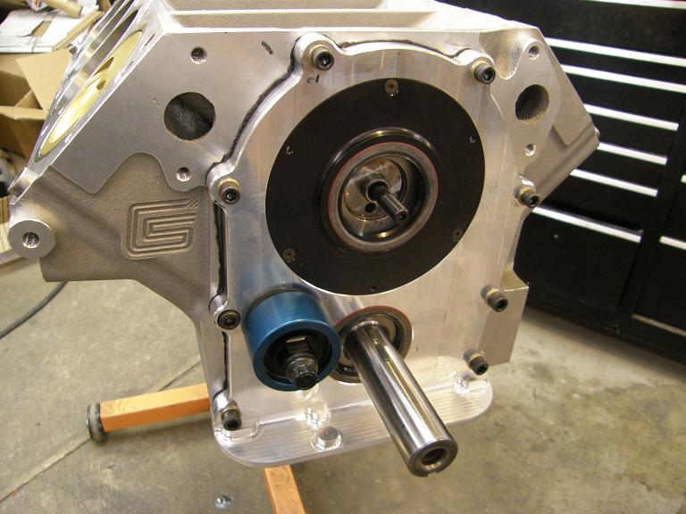
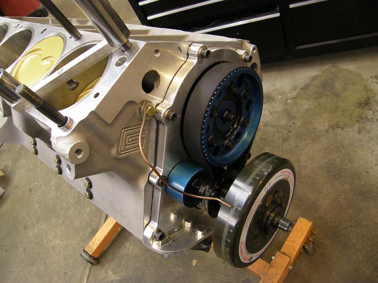
The Danny Bee belt drive also comes with a Torrington bearing thrust washer setup for the cam, with a machined thrust plate, very similar to the setup that Doug Garifo at Precision Oil Pumps sells. I installed the cam in the block, and then installed the two thrust washers and the Torrington bearing into the thrust plate and bolted that into position. Next I put the remaining two thrust washers and Torrington bearing on the cam pulley and installed that pulley onto the cam. I checked endplay as specified in the directions, and found I had .007", which was with their recommended range. With all this stuff test fitted in place, I pulled the cam pulley and the bearing and washers on that side, and installed the machined aluminum front cover that comes with the Danny Bee setup. Here's a photo of the front of the block at this point:
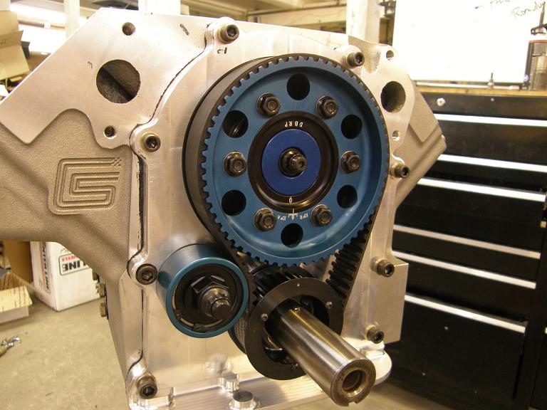
Finally I installed the pulleys and the belt, and tensioned the belt according to the instructions. Installing the cam pulley was a little tricky, because I had to line up the cam dowel without being able to see what I was doing, and also the thrust washers and Torrington bearing had to be kind of forced through the rubber seal, carefully, before the cam pulley would fit into place. Finally after about an hour of screwing around I got this stuff put together; here's a photo:
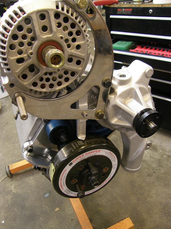
With the timing belt setup installed, I temporarily installed the crank sleeve, harmonic balancer, the water pump, and the alternator and alternator bracket. I wanted to see what I had to work with in terms of fabricating a timing pointer, because obviously with the Danny Bee setup a stock pointer wasn't going to work. Next I installed a piston stop and temporary pointer so I could determine top dead center; see the photos below:
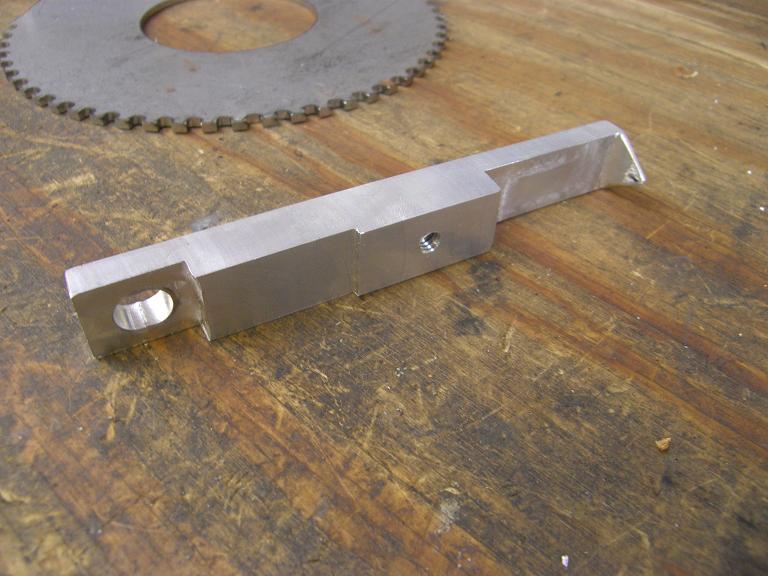
After setting the crank at top dead center, I figured out how I could machine a simple pointer that would bolt to the water pump and the alternator bracket. All these little machining projects take time, but they are worth it in my opinion. Took about an hour and a half to make up this little pointer; here's a photo, and also a picture of it installed on the engine:
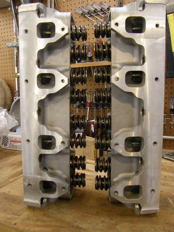
Next I decided to mock up the valvetrain and degree the cam, and check piston to valve clearance. First thing to do was to remove the valvesprings from cylinder 1 and replace them with checker springs. The heads have been sitting on the shelf ready to go since 2007; they are the best flowing FE wedge heads I've ever had. I had them check on two different flow benches, a Superflow SF-600 and a Superflow SF-1020. On the SF-600 they flowed 401 cfm at .800" lift on the intake, and on the SF-1020 they flowed 390 cfm at .800". Notably, on the SF-1020 the heads flowed better in the low range than they did on the SF-600. Exhaust flow on both benches was in the 265 cfm range if I recall correctly. Area under the curve from zero to .800" lift was nearly the same with both benches. The heads use 2.300" intakes and 1.75" exhausts. Here's some pictures of these heads:
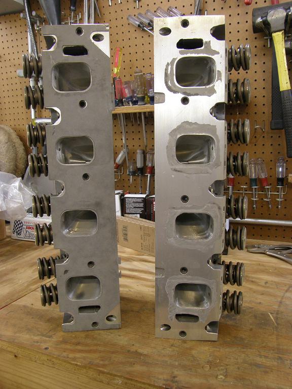
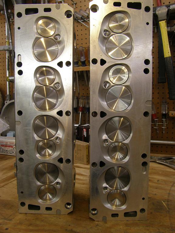
If you look closely on the exhaust port side of the heads you can see an area that has been machined. I did this, to take off some material on the head and allow for easier fitment of the headers in my Mach 1's engine compartment (which was where this engine was originally destined to go). I shaved off about .070", which doesn't seem like much, but every little bit helps since the Blue Thunder heads have raised exhaust ports, making fitment in the engine compartment more difficult.
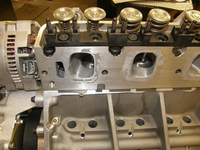
I installed the four head studs around cylinder 1, put on the Cometic head gasket for that side, and installed the heads with the checker springs on number 1; here's a photo:

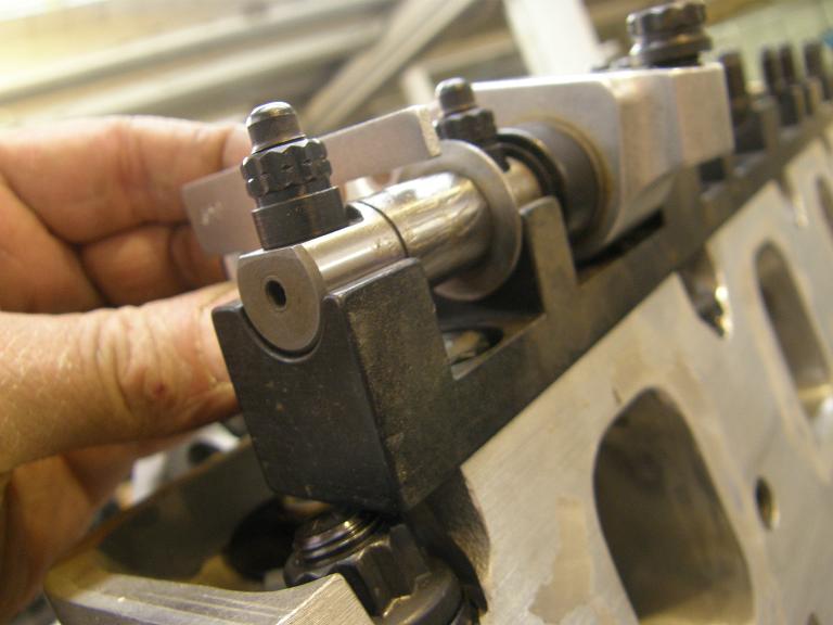
The Blue Thunder heads are designed to be used with a custom T&D rocker arm setup, so I bolted that on next. First step is to bolt on a plate that the rockers themselves in turn bolt to. Here's a picture of the plate:
Next, you have to check to make sure that the rocker arm shaft is at the correct height with respect to the valve, and then space this plate up if necessary. The T&D rockers come in pairs on their own small shaft, so that there are actually 8 different rocker shafts on the engine when everything is assembled. In order to use the gauge that comes with the rockers to check the height of the shaft, the checker spring had to be removed from one valve and one of the rockers had to be removed from the shaft. Here's a photo of the checker gauge, showing that the shaft needs to be raised around .200" in order to provide the correct rocker arm geometry:
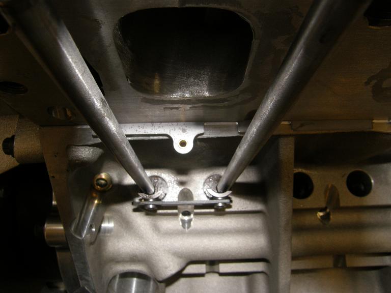
T&D provides machined washers to use as spacers, so I installed them to the correct thickness under the plate and then reassembled the checker spring to the valve and the rocker arm that I had removed to the shaft. Then, with my Smith Brothers pushrods in hand, I assembled the valvetrain for cylinder #1. The lifters are Comp Cams roller lifters for an SBC; because of the width of the ports on the high riser heads, I needed an offset pushrod location, and it wasn't available with an FE lifter. Here's a photo looking down the pushrods at the lifters; you can see that the intake lifter has the pushrod seat offset, while the exhaust lifter has it centered:

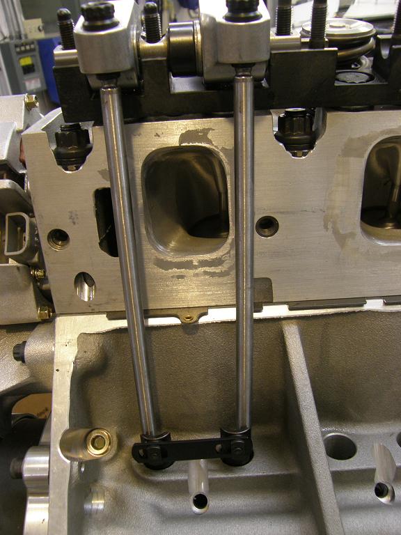
This matches up well with the T&D rockers, which feature an offset intake rocker arm. However, I also have the option of using an offset lifter on the exhaust side, even though the exhaust rocker is not offset. Here's a photo of the lifters where I've installed the offset exhaust lifter also:
Using two offset lifters instead of one gives me more room around the port on the exhaust side, and I think I may need that. Here's a photo of the complete valvetrain assembly with this setup:
I ran out of time to degree the cam and do the piston to valve clearance check tonight, so I'll have to keep working on that next week. I'll post an update on this project when I have more information and photos, probably in a week or two.


