This week I got started on my new 519" SOHC engine. I last ran this engine in 2009, after rebuilding it after the rocker arm fiasco of Drag Week 2008. In the summer of 2009, with about 700 miles on the engine with the new T&D rocker arms, I broke the long timing chain in the motor. I'm still not sure why that happened, but I suspect a combination of excessive valve spring pressure and a factory style chain led to this failure. Fortunately, I was also putting my 585" SOHC together at the same time, and since it was ready before DW'09 I decided to pull this motor and put in the bigger engine.
I was preparing to put this motor back together as a 500" engine with the 4.375" stroke crank that it had originally come with, when I decided to make the changes to my high riser engine to reduce the stroke, in order to fit a bigger cam in the engine. That left the 4.500" stroke crank from the high riser available for this motor. Since there are no rod to cam clearance issues with a cammer, the big stroke was no problem.
Along with the 4.500" stroke I wanted to make a few other changes to this engine. I had acquired the parts necessary to upgrade the cam drive to one of Paul Munro's setups. Paul's drives use a .250" pin roller chain for the secondary chain, as compared to the .222" pins used on the original style chains. Paul's chains are also true roller chains, whereas the .222" chains are not. Paul's gears are also nitrided like the original Ford gears, rather than flame hardened like some of the cheaper versions are. Having broken one SOHC chain, I had absolutely no desire to repeat that experience, so despite the cost of Paul's setup (around $1000) I decided it was worth the cost.
I also needed to switch to different connecting rods (6.625" center to center rather than 6.700") and thinner head gaskets (0.275" Cometics, rather than the standard .040"), in order to be able to use my new pistons with the bigger stroke of the new crank. The T&D rockers I had were the aluminum versions, and several had been damaged when the chain broke, so I have replaced them with a set of the steel T&D rockers. Finally, I decided to upgrade the cams on this engine to Comp's most recent lobe profiles, rather than the older style cams I'd previously been running. I will fit this engine in the end with the same Hilborn EFI system I've used previously on both SOHCs, but a local friend of mine happens to have a sheet metal intake with two Dominator carbs for an SOHC, so I will start with that intake on the engine for some dyno tests.
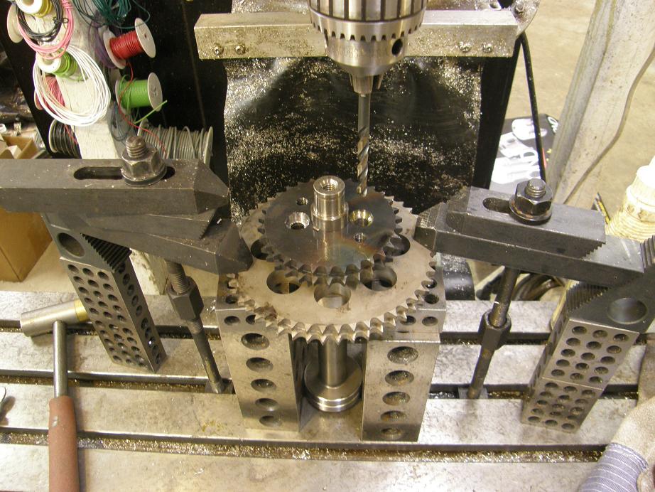
The first thing I decided to do on this build was to put together the stub cam assembly. This would be pretty simple if I was content to leave everything assembled like stock, but previous experience with shearing a stub cam key and the resulting engine damage on my first cammer back in 2006 has taught me that the primary and secondary gears on the stub cam should be pinned together to prevent this kind of failure. I have developed a technique for doing this that gives me a lot of confidence, but it requires some substantial modifications to the parts. I got going on the modifications this week. The first thing that has to be done is some half moon shaped cutouts have to be made in the secondary drive gear. I did this on my CNC machine with a carbide end mill, going very slowly. Just like the Ford gears, Munro's gears are very, very hard, and cutting them is very difficult. However, going very slowly and enduring a lot of noise from the machine, I was able to make the modification; see the photo below:
The half moon cutouts are for a 5/8" diameter steel bar that needs to be welded in place in each cutout. I cut two 1/2" long sections of the 5/8" bar and Tig welded them to the stub cam gear. Then it was back in the CNC machine where holes were machined flush with the back of the gear and drilled for bolts that would screw into the primary (larger) timing chain gear. Again it was very slow going. Here's a photo of the gear at this point:
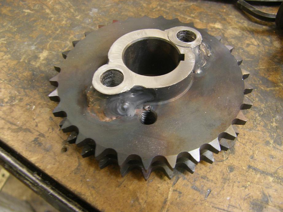
Finally I had to flip the gear over and counterbore some holes on the other side, so that the boltheads that went in through this gear would be flush with the top of it; if you don't do that, the bolt heads will hit the front cover when you try to install it.
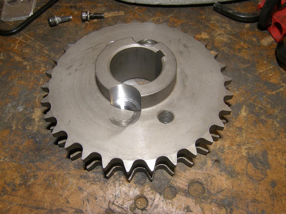
Next I pressed both gears onto the stub cam, and got set up in the Bridgeport to drill and tap some 5/16-18 holes in the larger gear. Here's a photo of the stub cam assembly at this point:
I have some special bolts I bought a while back that have a 3/8" solid shank, and a 5/16" thread at the bottom, and the plan was to drill and tap the larger gear and install these bolts to pin the two gears together, so that one couldn't move with respect to the other and upset the cam timing. Unfortunately, drilling the large gear turned out to be impossible with the drill bits I had on hand; the gear was really, really hard, and in the Bridgeport I just couldn't apply the required pressure to get the bits to start cutting. As a result I left this task for later in the week, when the carbide drill bits I ordered today will arrive. Of course, even after I drill the gear it may prove to be impossible to tap it. In that case I will have to drill the hole in the big gear to the same size as the one in the small gear, and press in a pin to lock the gears together.
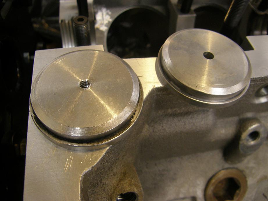
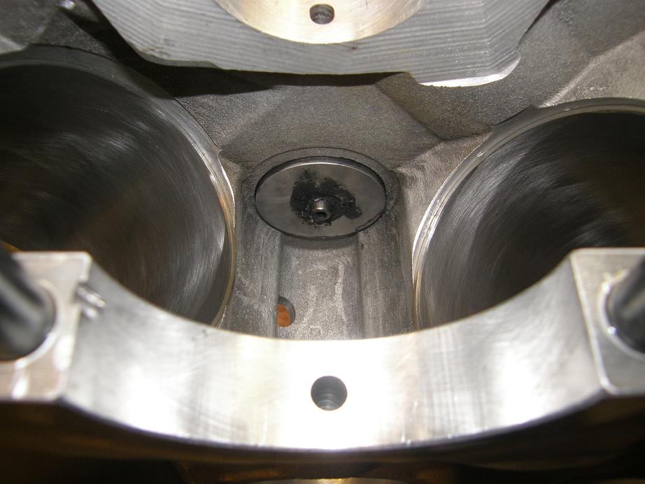
Next I turned my attention to the short block. This engine uses an aluminum Pond block, which is specially built for use with a cammer. There are a lot of oil passages that are not drilled because the cammer doesn't need them, and other machining operations are left out too. For example, there are no lifter bores in this block, and so the oil galleries running down the lifter bank on each side don't go anywhere. The top oil gallery in the middle of the block is also non-functional, because the oil hole to the number five cam bearing isn't drilled. Also the oil hole to the number three cam bearing isn't drilled, but the number 2 and 4 holes are, because the stock SOHC uses these like a normal sideoiler block to route oil to the heads. Oil to the left head goes through the groove in the second journal of the stub cam, just like it would with a normal FE cam sideoiler cam journal. But of course there is no cam journal in the SOHC at number four. Ford solved this problem by grooving the back side of a normal cam bearing to transfer oil between the two holes in the cam bearing journal, and direct it to the right head. I've put a few SOHCs together like this, but eventually I started checking the oil pressure at the heads while the engine was running, and the right head was always down on pressure compared to the left one with that grooved cam bearing installed. As a result, now I make a custom plug for the number 4 cam bearing bore, that doesn't restrict the oil that goes to the head. Here's a photo of the two piece plug, and another showing the plug installed in the block:
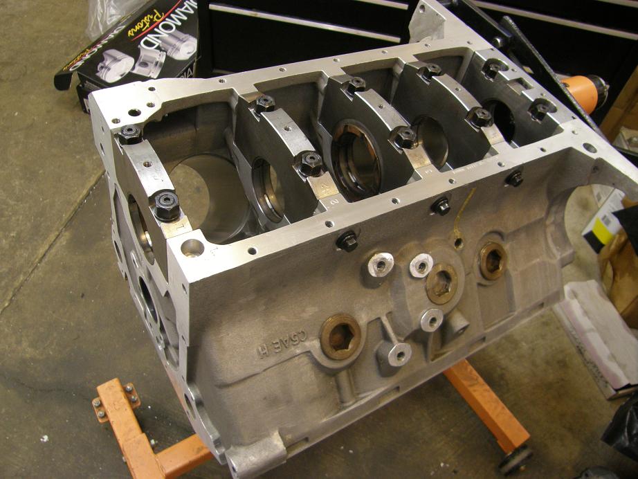
After getting the plug installed, I started assembly of the short block. This always seems tedious to me, and this engine was no exception. First I did a thorough job of cleaning and blowing out the block, then I set the crank up on the bench and measured all the main bearing journals. Next I assembled the main bearings into the block, torqued all the caps, and used a dial bore gauge (set up off the micrometer I used to measure the mains) to measure the ID of each bearing set. Calculating the bearing clearance it looked a little high, around .0032 to .0036, but still OK, especially given the oil I plan to run in the engine (Valvoline 20W-50 racing oil). Here's a photo of the block with the bearings installed and the main caps torqued in place:
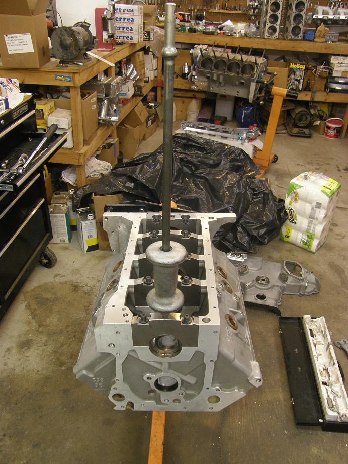
The Pond and Shelby aluminum blocks have an interference fit between the steel caps and the aluminum block casting. As a result, you have to use a slide hammer to remove the caps. Each cap has a 5/16-18 thread in the top of it to screw the slide hammer into. Here's a photo of my slide hammer installed, getting ready to remove the caps after checking the main bearing inside diameters:
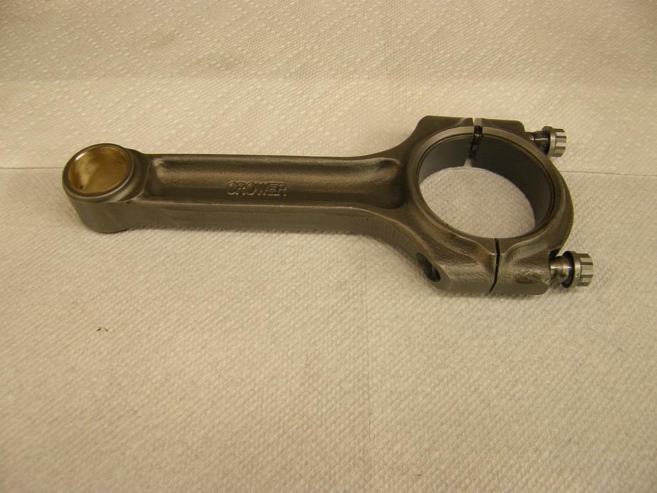
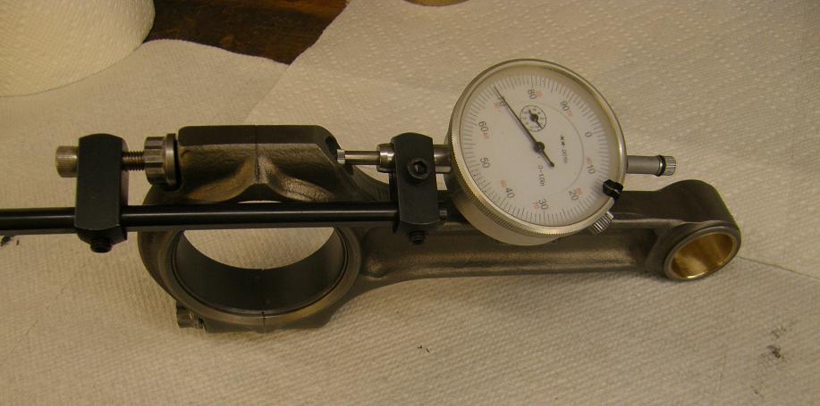
Next I did the same thing with the rods, measuring the rod journals on the crank, and then assembling each rod with its rod bearings and measuring the ID to determine the clearance. Here's a photo of one of the rods; these are supposed to be good for 1000 horsepower:
With my newly calibration-checked torque wrench I torqued the bolts and then checked the stretch to make sure it was within specifications. Crower says the rod bolt should stretch .005" to .007", and mine were all in the .005" to .006" range. Here's a shot of the rod bolt stretch gauge on one of the rods:
After the calculations the rod bearing clearance came in right on the money, running from .0022" to .0026".
With all this checking of course I expected no problems with the short block going together. I took everything back apart, then lubed the main bearings, set the crank in the block, installed the caps and torqued the main bolts and cross bolts to spec. Then I tried to spin the crank. It was dead stuck; would not budge! I was pretty confused for about 30 seconds, and then the problem dawned on me. Thinking back to my first assembly of this block in 2006, I had installed the Scat 4.375" stroke crank and had the same problem. It had taken me all day back then to figure out that the oil slinger on the back of the crank was too big in diameter, and was bottoming out in the groove in the block. So, when the caps were torqued, the crank froze in the block. I'd had to take the crank out and cut .020" off the diameter of the oil slinger to eliminate the interference.
I figured I had the same problem all over again. I tore the crank back out of the block, and sure enough I could see witness marks on the outside edge of the oil slinger. Back when this had happened before, I figured it was the Scat crank. But having the same problem with two of them, maybe its the Pond block instead; maybe the groove in the block and cap for the oil slinger just isn't deep enough.
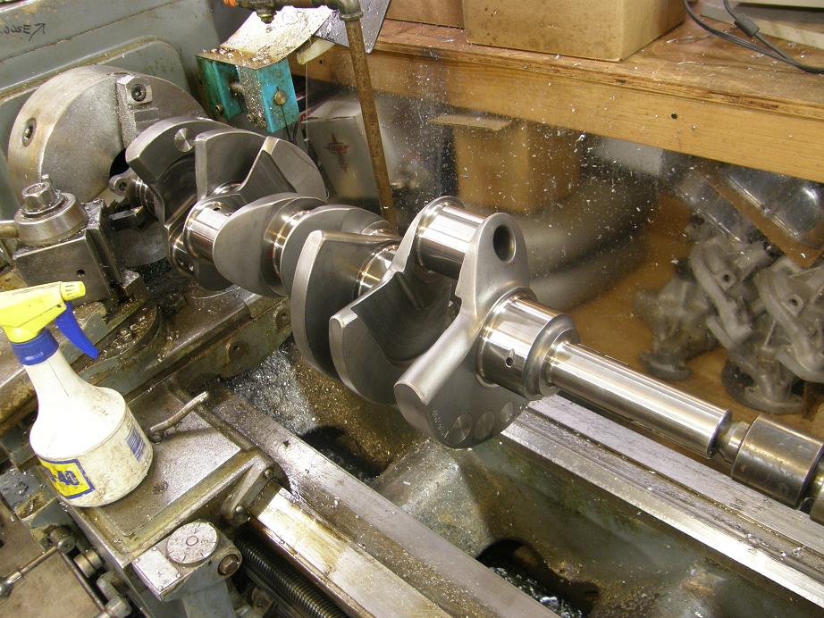
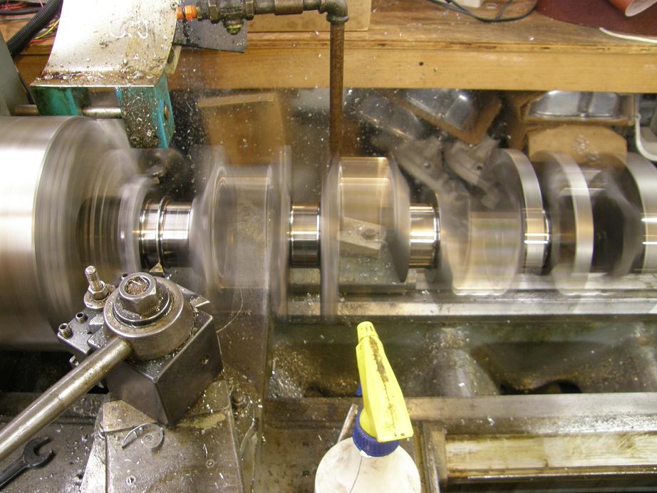
In any case, the solution was fairly simple. Situations like this are the reason I've put some machine tools in my shop over the last ten years or so; rather than being stuck for a week, taking the crank somewhere and waiting for some place to do this work, I can just stick it in my lathe and take care of the problem. Here's a shot of the crank in the lathe, and another with it spinning while I'm cutting the outside diameter of the oil slinger:
After recleaning the crank and re-lubing the bearings, it installed in the block and this time spun over beautifully. On to the pistons. Here's a photo of some of the reciprocating components on the bench prior to installation:
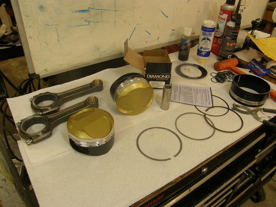
The pistons are 12.5:1 Diamond slugs, coated on the top and sides, and fitted with a low tension ring package including .043" steel top rings, .043" Napier second rings, and a 3mm low tension oil ring combination. The rings are file fit, so I set the top ring up for a .020" end gap and the second for .024". One nice thing about a low tension ring package is that it is easy to install; I used a tapered ring compressor from Summit and the first piston and rod assembly slide right into the bore:
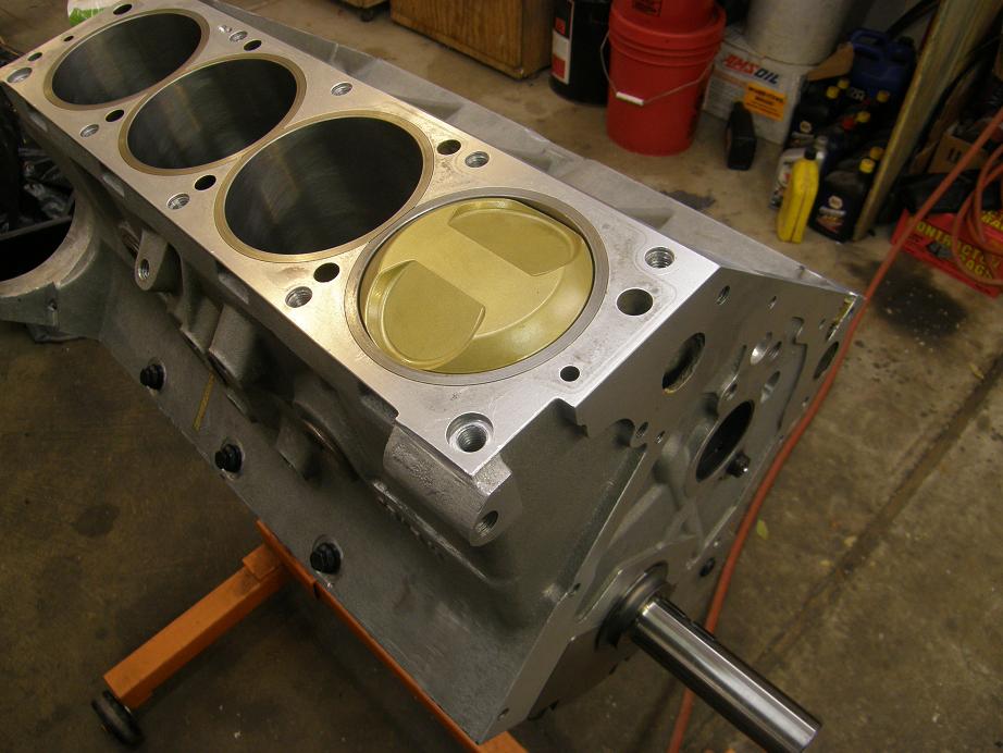
I got one more piston installed before I called it a day today. I should be able to get the rest of the pistons installed this week, and hopefully finish up the stub cam work, so that next weekend I can assemble the heads, install them, and start working on getting the timing gears and chain installed. I'll post another update on this engine next weekend.


