Author Topic: Project Rusty Junk  (Read 14298 times)

0 Members and 1 Guest are viewing this topic.

blykins

  • Hero Member
  • *****
  • Posts: 5134
    • View Profile
    • Lykins Motorsports
Project Rusty Junk
« on: March 09, 2015, 01:44:41 PM »
From the other forum....

Well, I figured today is as good of time as any to showcase a personal toy that I've been working on.  I hardly ever get time to do anything for myself, so it's just a process of whittling away at it over a year or two.  How do you eat an elephant?  One bite at a time...

Part of being an engine builder is the fun of trying new things and seeing all the different parts, pieces, and technology out there.  I don't have the R&D budget that some of the others do, so I tend to think on smaller scales.   Also, part of being an engine builder is learning how to make the most of something...whether it's small or large.  Making big horsepower with a small engine has always intrigued me as it takes more dedication, knowledge, experience, and foresight to get good results.
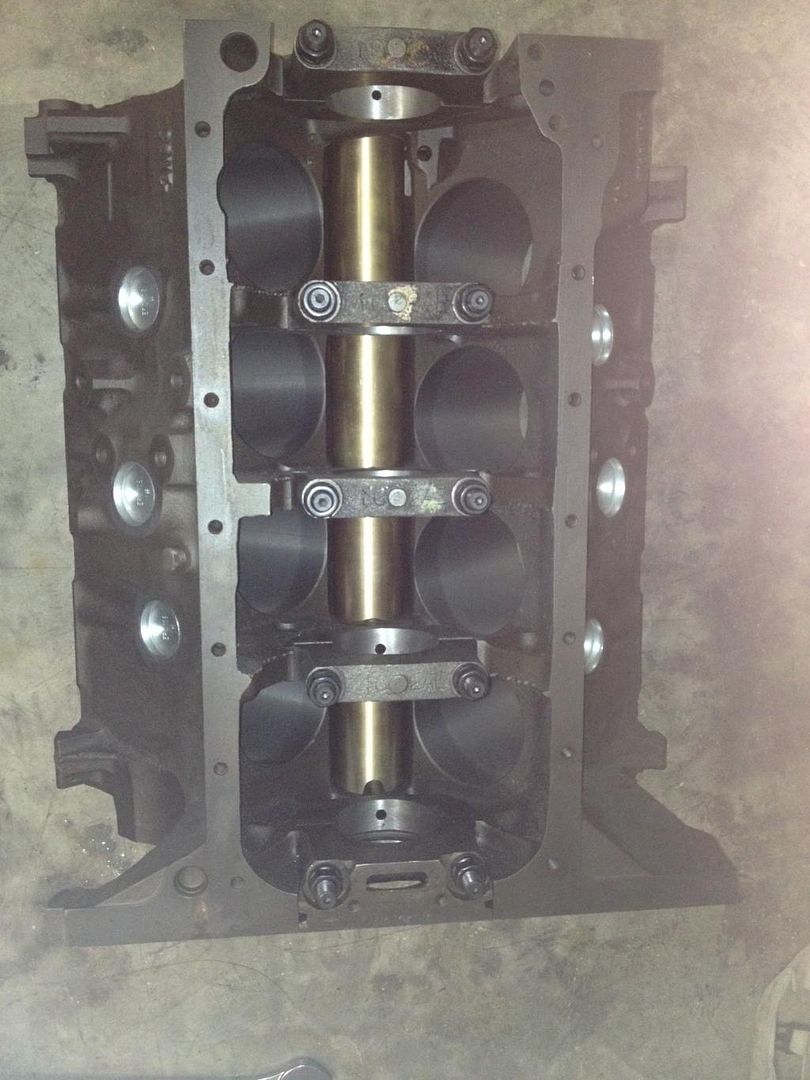
Enter my 352:


Yep.  That 352 in the bottom of the picture.  I bought it out-right (didn't make payments) from a forum member around the middle of 2013.  I had plans of taking it straight to the dyno and just treating it horribly, but after I pulled the valve covers, I didn't want to take a chance of scattering it and making a mess of the dyno room. 

It was a turd....


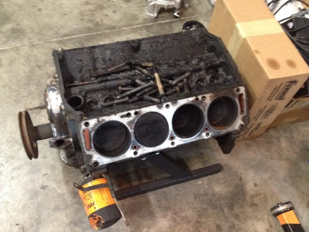
I've always wondered what a real hipo, high rpm 352 would sound like and since I have a bunch of spare parts laying around, I decided to do some tinkering and playing.  I also wanted to use the engine as a "mule" and showcase some other things I've been pondering.

Ok, so I stripped her down, and had the block baked and tumbled.  I sent the crank to Adney and had him turn the rod journals down to BBC size and to do some other work to it. 

When the block came back, I tapped all the passages for pipe plugs, massaged this, massaged that, then did a half fill with some Moroso block filler. 

You don't see a lot of published cases of cylinder vents in FE's, but they do them with LS engines, Modular Fords, Cummins, etc., so I added those as well.  Since they are in so many factory and aftermarket blocks, I don't feel like I'm betraying any speed secrets by mentioning them here.  If you're not familiar with them, they allow adjacent cylinders to scavenge and equalize pressure.  What's it worth?  A little bit of ET...


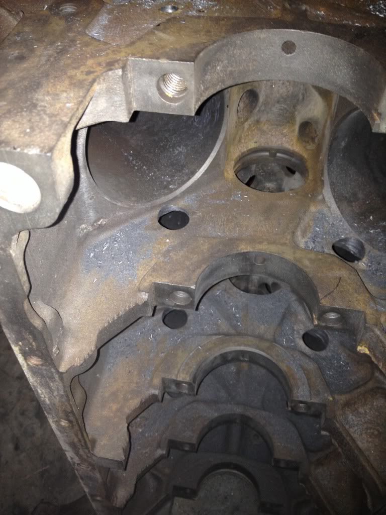
Had it line honed with ARP main studs, square decked, bored and plate honed to a final bore size of 4.060".  Starting to look like a nice piece.  :)

One of the biggest contributors to making horsepower is controlling crankcase pressure and windage.  If you can keep oil from raining on the rotating assembly, you will see gains.  If you take a look at a lot of roundy-round blocks, Cup blocks, high-end drag racing blocks, etc., you see the incorporation of an enclosed cam tunnel.  This does exactly what you think it would do...it shields the rotating assembly from the oil coming off of the camshaft and from the lifter valley up above.  Some high-end blocks are designed with integrated cam tunnels.  Other blocks just use shaped sheet metal, basically half-pipes, and they are fastened to the block bulkheads. 

I had an idea in my head for the longest time about another method and basically came up with a REAL enclosed cam tunnel for an FE. 

I threw around some ideas, did some brainstorming, then ordered up a tube of bearing bronze and shipped it to my buddy (and forum member) Wade White.  Wade is a master machinist and has access to some cool toys, so I felt very comfortable working with him.  Wade also does all of my custom valve covers, so I'm familiar with the quality of work that he does.

An FE block has different sized cam bearing OD's.  That makes things tricky, but it also lends itself to a fully functional drop-in enclosed cam tunnel.  I measured up some cam bearings, factored in some press fit dimensions, calculated some area for a distributor gear to fit, drew it up on AutoCAD, then sent the drawing to Wade.

Out came this:


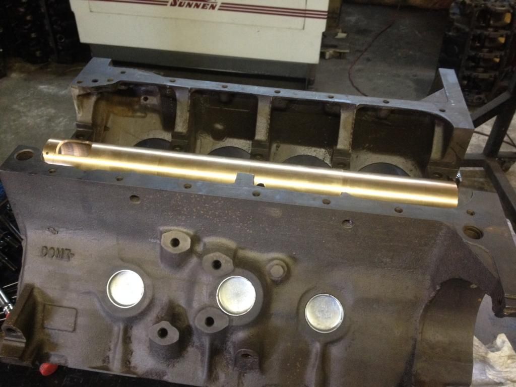
That was the first draft.

The design intent is to drop the tube in until the last 5/8", then due to the stepped IDs of the cam tunnel, it's then a press fit.  This allows you to get the tunnel started in very straight, located correctly, then locked in without much effort.  I use a roller cam bearing tool to draw it in, and the good thing is, you can draw it right back out so that you can clean the block easily. 

So, after I got the first one in, I had to do some more brainstorming. 

1.  How do I oil the cam? 
2.  How do I drain the oil that's in the tunnel to keep the oil temps from creeping up and to keep from filling the lifter valley with oil?
3.  How do I keep the oil in the valley from raining down around the tunnel?
4.  How do I finish the inside diameter of the tunnel?


Here are the answers:

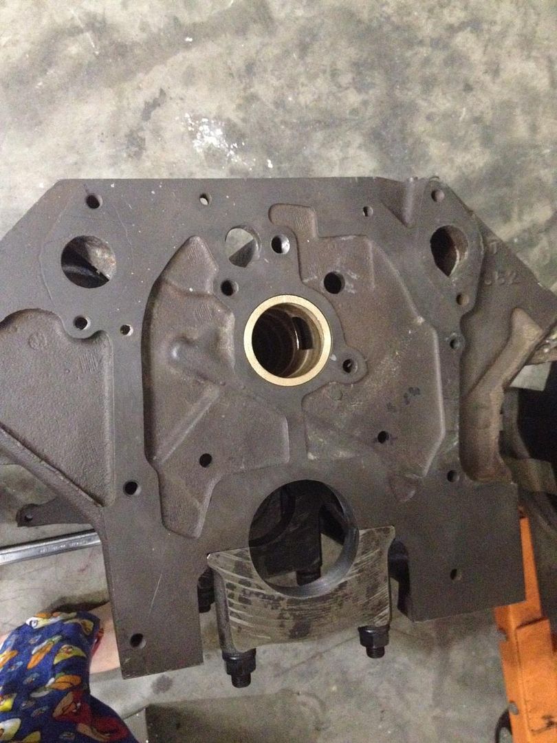
1.  I drilled small holes in the tunnel that line up with the feeds in the mains.  It will oil like a regular cam bearing.
2.  I drilled and tapped (2) 1/4" NPT holes, one on each side of the thrust bearing, on opposite sides of the block.  These holes are tucked in close to the #3 main bulkhead and allow the use of a -6AN fitting, hooked to a -6AN hose, which is loop clamped to the block bulkhead, then the hose drains directly into the oil pan, away from the crankshaft.  I'm using a highly modified FT bathtub pan, and the drain hoses drain directly to the pickup. 


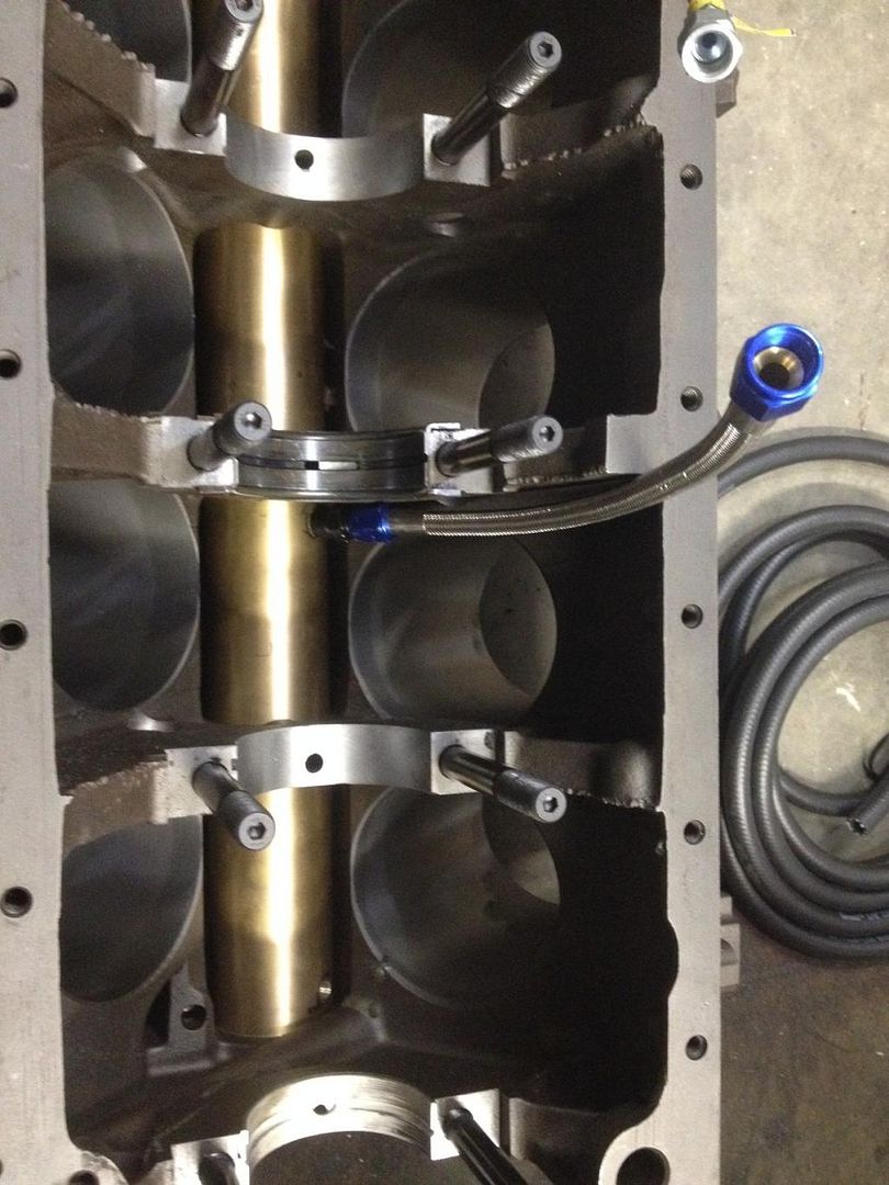
And yes, the rotating assembly clears them. 

3.  The drain holes in the valley of the block are plugged with 3/4" cup plugs.  The holes at the front and rear of the block are left intact, so what little oil that's up there can drain to the timing cover area and to the very rear of the block under acceleration. 

The heads are drilled for external drain lines, so that they don't drain to the lifter valley, but straight to the pan. 

4.  This is the tricky part and you have to have access to some highly specialized machining tools.  I do plan to offer these, but keep in mind that you will have to work hand-in-hand with a machinist that has FE specific tools, such as a BHJ lifter tru fixture for an FE and a way to press in bronze lifter bore bushings. 

The block lifter bores get drilled for the OD of the bushing.  The tunnel then gets pressed into the block, and then the same fixture is used to cut the lifter holes into the tunnel.  Once that is done, then the lifter bore bushings are pressed in and they extend down into the tunnel by a small amount.

I will post pictures of all this later on.

With the cam tunnel and lifter valley essentially sealed off, crankcase pressure will need to be vented by other means. 

Once the bushings are in, then the ID of the tunnel needs to be bored/honed to fit the FE camshaft size.  Again, a specialized fixture is used to align both the crank and cam tunnels and everything is made perfectly straight and true. 

Ok, so that's the nuts and bolts of that.  I think it's cool stuff myself. 

How much hp will it net?  I can't exactly give you a specific figure on this particular engine, but back-to-back tests on the dyno and ET with other engines show averages of 10-15 hp increases.

For the rest of the engine...

It's a solid roller engine and I've got a custom Comp Cams cam for it, "inching" towards .800" lift, and having a pretty healthy duration. 

Pistons are custom flat tops from Racetec, using a .990" pin size, and a .043/.043/3mm Mahle ring pack. 

The heads are some Dove Canadian CJ heads.  They were given to me by Gary Veres, my Tunnel Port customer.  I gave him a set of JE pistons that I had on the shelf a while back and he says that he's trading the heads for the slugs, but I know it's just because he's a cool and kind-hearted fellow FE'er. 

I just received them a few weeks ago and haven't had a time to start crunching on them, but they will get the full treatment from Lawes Mayfield, along with a Performer RPM intake manifold.  I actually had some BBM heads set aside for this project, but I was leery about the chamber shape and the throat size being too large for the bore size and for the size of the valves that I need to use.  If you remember correctly, we had a 170cc port on those heads flowing around 340 @ .800" with a 2.125" intake valve and around 250 on the exhaust side with a little teeny 1.600" valve.  I can attest to the quality and performance of those heads, especially with a <i>filled</i> intake floor.  However, I felt best to use another head and to use the BBM's for another project.

As always, I will keep everyone up to date on the status of the rust bucket.  A little head and intake work and it will be ready to assemble and beat up on the dyno. 

I would like to see 600 hp at around 7500-8000 rpm out of it.  It's good to have goals and it's good to gain some knowledge and some parts that I can use down the road in some of my race engines. 

Brent Lykins
Lykins Motorsports
Custom FE Street, Drag Race, Road Race, and Pulling Truck Engines
Custom Roller & Flat Tappet Camshafts
www.lykinsmotorsports.com
brent@lykinsmotorsports.com
www.customfordcams.com
502-759-1431
Instagram:  brentlykinsmotorsports
YouTube:  Lykins Motorsports

Heo

  • Hero Member
  • *****
  • Posts: 3380
    • View Profile
Re: Project Rusty Junk
« Reply #1 on: March 09, 2015, 02:06:29 PM »
I like the way you think :)


The defenition of a Gentleman, is a man that can play the accordion.But dont do it

MRadke

  • Full Member
  • ***
  • Posts: 140
    • View Profile
Re: Project Rusty Junk
« Reply #2 on: March 09, 2015, 02:25:20 PM »
Hopefully you'll excuse the dumb question.  Does that sleeve replace the cam bearings?

blykins

  • Hero Member
  • *****
  • Posts: 5134
    • View Profile
    • Lykins Motorsports
Re: Project Rusty Junk
« Reply #3 on: March 09, 2015, 02:27:07 PM »
Yes, the tunnel is the "cam bearing". 

I explained this in a follow up post on the other forum, but the mains feed to the tunnel just like a regular cam bearing.  The front of the tunnel has an additional hole for distributor oiling, and a groove connecting the two holes, along with a groove to the timing set.
Brent Lykins
Lykins Motorsports
Custom FE Street, Drag Race, Road Race, and Pulling Truck Engines
Custom Roller & Flat Tappet Camshafts
www.lykinsmotorsports.com
brent@lykinsmotorsports.com
www.customfordcams.com
502-759-1431
Instagram:  brentlykinsmotorsports
YouTube:  Lykins Motorsports

turbohunter

  • Hero Member
  • *****
  • Posts: 2515
    • View Profile
Re: Project Rusty Junk
« Reply #4 on: March 09, 2015, 02:31:04 PM »
Another dumb question.
If the cam tunnel is fed off the block oil galleries, how do you keep the tunnel in place?
Is it that good of a press fit?
OOPs
Upon rereading, the holes in the tunnel are grooves so that if it rotates there's no big deal. Is that correct?
If so cool. Well, it's cool no matter what.
« Last Edit: March 09, 2015, 02:41:33 PM by turbohunter »
Marc
'61 F100 292Y
'66 Mustang Injected 428
'66 Q code Country Squire wagon


blykins

  • Hero Member
  • *****
  • Posts: 5134
    • View Profile
    • Lykins Motorsports
Re: Project Rusty Junk
« Reply #5 on: March 09, 2015, 02:41:14 PM »
It's a press fit.  It can't rotate, and if it did, then it would bind all the lifters up.  :)  The lifters go down into the tunnel through the lifter bore bushings. 
Brent Lykins
Lykins Motorsports
Custom FE Street, Drag Race, Road Race, and Pulling Truck Engines
Custom Roller & Flat Tappet Camshafts
www.lykinsmotorsports.com
brent@lykinsmotorsports.com
www.customfordcams.com
502-759-1431
Instagram:  brentlykinsmotorsports
YouTube:  Lykins Motorsports

turbohunter

  • Hero Member
  • *****
  • Posts: 2515
    • View Profile
Re: Project Rusty Junk
« Reply #6 on: March 09, 2015, 02:43:57 PM »
Oh yeah, those pesky things :o
Yeah I guess that makes sense (head slap).
That's even more impressive that it all works and doesn't deform on the press in.
Wade is pretty darn good.
« Last Edit: March 09, 2015, 03:09:26 PM by turbohunter »
Marc
'61 F100 292Y
'66 Mustang Injected 428
'66 Q code Country Squire wagon


NIsaacs

  • Sr. Member
  • ****
  • Posts: 302
    • View Profile
Re: Project Rusty Junk
« Reply #7 on: March 09, 2015, 04:00:34 PM »
I am gonna watch this build, I like the 7500-8000 rpm stuff and the mention of "Cummins".... FE and Cummins is like bread and butter!

Nick
2021 Ram 2500 4x4 Cummins of course!
2017 Ford Escape, 2.0 Eco Boost
2001 Ram 2500 4x4 QC short bed, Cummins, 6spd, some mods
1991 Dodge D250, reg cab, Cummins, 5spd, mods
1974 F-350, Cummins, 5spd, 3spd aux, mods
1975 F-250 4x4, 428, C-6, Sled Puller

fastback 427

  • Sr. Member
  • ****
  • Posts: 442
    • View Profile
Re: Project Rusty Junk
« Reply #8 on: March 09, 2015, 04:50:17 PM »
Very cool build. It will be fun to see how much HP your little "tricks" will get you. What will be your cu. in. And compression?  Will you be flowing the heads , porting them or just run them as is? Interested because I have a set of f5 dove heads on my fairlane and they flow very well. Good luck and we'll be watching with interest.
Jaime
67 fastback 427 center oiler 428 crank Dove aluminum
top end toploader
67 fairlane gta cross bolted 12:1 390 Dove aluminum top end c6 3600 stall
65 falcon straight axle project
67 mustang coupe project
76 f350 dually 390 mirror 105 4bbl 4spd
74 f100 xlt 390 c6 factory ac

blykins

  • Hero Member
  • *****
  • Posts: 5134
    • View Profile
    • Lykins Motorsports
Re: Project Rusty Junk
« Reply #9 on: March 09, 2015, 05:02:47 PM »
It is a 363.  Had planned on 11:1 with the BBMs, but with the Dove heads, I'll have to measure and see where I am.  If I'm sitting pretty, they may get angle milled. 

The heads will be ported.  They will be flowed before and after.  I'm curious myself as I've seen numbers around 280 from these heads out of the box.  Ported they should do really well. 
Brent Lykins
Lykins Motorsports
Custom FE Street, Drag Race, Road Race, and Pulling Truck Engines
Custom Roller & Flat Tappet Camshafts
www.lykinsmotorsports.com
brent@lykinsmotorsports.com
www.customfordcams.com
502-759-1431
Instagram:  brentlykinsmotorsports
YouTube:  Lykins Motorsports

cammerfe

  • Hero Member
  • *****
  • Posts: 1676
    • View Profile
Re: Project Rusty Junk
« Reply #10 on: March 09, 2015, 06:11:08 PM »
Brent, Jim Dove has drawings and information regarding the porting of those heads. The valve pocket has what he calls an 'ice-cream-scoop' shape and the transition is somewhat unusual on the short side. I used a set for a project several years ago; had Wayne Kuchtyn at Headwinds do the work according to the instructions. On the 1020 Superflow at Livernois we saw 338 at 28 inches and .700 lift. I believe we used a 4.100 cylinder fixture, if I remember correctly. I used 2.100 Ferrea nailhead intake valves.

KS
« Last Edit: March 09, 2015, 06:20:02 PM by cammerfe »

fastback 427

  • Sr. Member
  • ****
  • Posts: 442
    • View Profile
Re: Project Rusty Junk
« Reply #11 on: March 09, 2015, 06:15:36 PM »
Those numbers are right in line with mine. I got low 290's at .600 lift with 30 degree valves and valve unshrouding.
Jaime
67 fastback 427 center oiler 428 crank Dove aluminum
top end toploader
67 fairlane gta cross bolted 12:1 390 Dove aluminum top end c6 3600 stall
65 falcon straight axle project
67 mustang coupe project
76 f350 dually 390 mirror 105 4bbl 4spd
74 f100 xlt 390 c6 factory ac

blykins

  • Hero Member
  • *****
  • Posts: 5134
    • View Profile
    • Lykins Motorsports
Re: Project Rusty Junk
« Reply #12 on: March 09, 2015, 06:28:54 PM »
Ken, I'll have to look for them.  That's about where I'd like to be on flow.
Brent Lykins
Lykins Motorsports
Custom FE Street, Drag Race, Road Race, and Pulling Truck Engines
Custom Roller & Flat Tappet Camshafts
www.lykinsmotorsports.com
brent@lykinsmotorsports.com
www.customfordcams.com
502-759-1431
Instagram:  brentlykinsmotorsports
YouTube:  Lykins Motorsports

jayb

  • Administrator
  • Hero Member
  • *****
  • Posts: 7566
    • View Profile
    • FE Power
Re: Project Rusty Junk
« Reply #13 on: March 09, 2015, 06:36:47 PM »
That's a really cool project, Brent, and I'm looking forward to seeing how it works out.  One thing I'd be concerned about is draining back the oil from the cam and lifters through those 2 #6 tubes.  Do you think those tubes will be enough?  And wouldn't you need them between each pair of cam journals, not just in the center?
Jay Brown
- 1969 Mach 1, Drag Week 2005 Winner NA/BB, 511" FE (10.60s @ 129); Drag Week 2007 Runner-Up PA/BB, 490" Supercharged FE (9.35 @ 151)
- 1964 Ford Galaxie, Drag Week 2009 Winner Modified NA (9.50s @ 143), 585" SOHC
- 1969 Shelby Clone, Drag Week 2015 Winner Modified NA (Average 8.98 @ 149), 585" SOHC


blykins

  • Hero Member
  • *****
  • Posts: 5134
    • View Profile
    • Lykins Motorsports
Re: Project Rusty Junk
« Reply #14 on: March 09, 2015, 06:49:20 PM »
Jay, it's probably not the most perfect scenario, but I think it will be adequate based on some other experiences I've had.  From what I've seen and think, oil moves quite freely through there, based on acceleration, deceleration, etc. 

In a drag race small block, we use pieces of sheet metal between the bulkheads, made like a half-pipe, and they are epoxied in place.  Usually in the rear, we use a 3/4" piece of tubing to drain. 

If it does raise the oil level and get into the valley a little, it shouldn't hurt anything, or if the level gets up, it can spill over onto the distributor gear.  The heads will drain straight to the pan and the top end will oil through the lifters/pushrods. 

I think Jon Kaase used some pieces of sheet metal epoxied in between roller cam bearings in an EMC BBF.  He had one large 3/4"-ish drain at the rear of the engine and it cycled the oil just fine while just being a dyno queen.   Of course the sun always shines on Jon, but hopefully I can catch some rays too.  :)

I did try to fit some smaller drains in the front and rear, but it was basically impossible due to how close the counterweights came to various points on the block, and the shape of the block itself.

It's just fun R&D and experience for some future builds that I have coming down the pipe.
Brent Lykins
Lykins Motorsports
Custom FE Street, Drag Race, Road Race, and Pulling Truck Engines
Custom Roller & Flat Tappet Camshafts
www.lykinsmotorsports.com
brent@lykinsmotorsports.com
www.customfordcams.com
502-759-1431
Instagram:  brentlykinsmotorsports
YouTube:  Lykins Motorsports