Author Topic: The Road to Drag Week 2014 - June 29  (Read 26824 times)

0 Members and 1 Guest are viewing this topic.

jayb

  • Administrator
  • Hero Member
  • *****
  • Posts: 7404
    • View Profile
    • FE Power
The Road to Drag Week 2014 - June 29
« on: June 29, 2014, 09:40:11 PM »
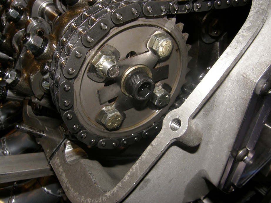
Another good week on the project, and a good weekend on the dyno this weekend.  After last weekend I was intent on trying to figure out the cam advance/retard situation with the cam sensors, so last Monday I ordered some more of the Honeywell cam sensors that I had used for this purpose back in 2006, along with some of the required triggering magnets.  These sensors pick up the presence of the magnet as it spins by the sensor, and provide a high speed digital output.  The magnets come in a little aluminum carrier with an 8-32 stud on the back, so all I had to do to mount them was to center drill and tap one of the bolts on each cam that holds the cam sprocket on.  Then the magnet carrier and magnet screw right into place.  Here's a picture of one of the magnets mounted on the cam sprocket:


After that I mounted the new sensors in the valve covers and set the airgap at about .060".  I had also wanted to make sure that I ran the two sensors off the same set of electronics, in case different voltage supplies or noise was causing one to be thrown off compared to the other.  So along with the magnets and sensors I picked up some other assorted electronics and made up this little circuit as shown below:


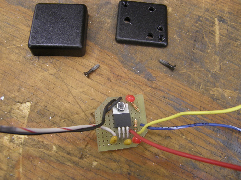
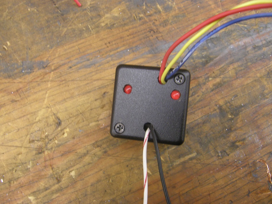
The device with the three legs is a common voltage regulator, with input voltage up to 30V and a 5V output.  The two yellow things are capacitors that are required when using the voltage regulator.  Then there are two resistors, and two LEDs, one set for each of the sensors.  I fit these together into a little plastic box:


With this arrangement I wired both sensors to the same 5V power supply and ground, and wired each sensor output into the resistors and LEDs, and then also fed each output into the MS3X control unit.

By Friday night I was all finished up with the electronics stuff, and decided to try another cam timing change.  My last change had been to advance the right cam from 105 to 102, and the left cam from 108 to 102.  This had resulted in a loss of about 20 HP, so I elected to go back a little, but keep the cams equally phased.  Working VERY carefully on Friday night, I got both cams backed up to 105.  On Saturday morning I fired the engine and ran the first test.  Thankfully power picked back up to the original level, or very close to it, but again the cam datalogs were confusing.  For the left cam, I was observing about the same thing that we observed last week, but the right cam looked much. much better.  It actually looked way TOO good, and was hardly moving at all during the warm up or the pulls.

For the cam sensor I am using two inputs to the MS3X.  The first input is dedicated to a cam sensor, and the second is an auxiliary input.  The left cam was on the cam sensor input, and it looked pretty much the same as last week, but the right cam did not.  After a little reflection this was even more puzzling, because last week, with different sensors, I was getting results on both inputs.  Really scratching my head on this one.  After a few more pulls and basically repetitive results, I called Scott Clark to ask him about this.  Scott suggested that I swap inputs to the MS3X and run another test.  I did this, and sure enough, now the right cam sensor looked like it had a believable signal, but the left cam sensor didn't.  This basically proved that the MS3X auxiliary input was smoothing or modifying the signal, rendering it useless.

At this point I made another change to the cam timing, moving both cams to an intake centerline of 108.  The LSA of these cams is 114, so now both cams were degreed 6 degrees advanced.  On the next pull I picked up a little more power, but not much, around 1.5 HP average across the 5500-7200 RPM range.  According to the cam sensor datalog, the left cam was retarding 9 degrees as I went into the dyno pull, and then retarded a further 5 degrees during the pull from 5000-7200 RPM.  That would mean that the effective intake centerline angle of the left cam was 8 degrees retarded, or 122 degrees, to make peak power on this engine. 

I just didn't believe this; that is so far out of whack with what I know about engines that it just doesn't pass the smell test.  After reviewing the data from both cams (including from the right cam when it was being logged by the cam sensor channel), I think one thing that I do believe is that during the pull, both cams are retarding about the same amount, 5 degrees or so.  It the data prior to the pulls is disregarded, that would put the existing timing of the cams as about straight up, which makes more sense from a power perspective.  I decided at this point to just abandon the cam logging experiment; I was chasing horsepower anyway, not cam angles.  I'm going to do some more experimenting with the cam timing next weekend, but I'm pretty close to dialed in at this point.

Now, with both cams at about 108, I decided to try another test.  I pulled the throttle bodies off the front of the intake and put them on top.  Here's a picture of this arrangement:


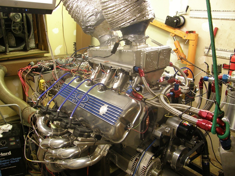
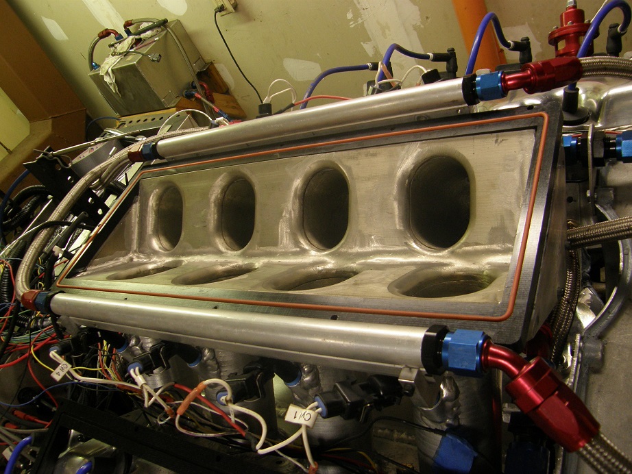
The motor definitely liked this change, picking up 10-15 horsepower across the top end power band, and not losing anywhere.  I kinda figured it would like that.  This also had an unexpected effect; prior to this pull, all the previous pulls had shown zero vacuum in the plenum.  But with the throttle bodies moved up top, suddenly I had 0.5 inches of vacuum in the plenum above 6500 RPM.  Apparently the engine was drawing the air more efficiently now and the throttle bodies were a restriction.  However, sometimes plenum volume plays into this kind of thing, and I had my second 1/2" plenum spacer ready to install.  Current plenum volume is 580 cubic inches with the first spacer, and the second spacer would increase that by 60 cubic inches.  So, I took some time and got the second spacer installed.  Here's a photo of the manifold with the top removed and the first spacer visible.  I machined these out of black Delrin, and cut them for an O-ring to make sealing them up easy:


After the installation the next pull got me another 7 average horsepower across the speed range, and back to zero vacuum in the plenum for the whole pull.  Along with that the engine seemed to be running a little leaner, so over the next few pulls I richened the top end up about 4%, and picked up a few more horsepower.

Throughout this whole process I still was not seeing any significant amount of crankcase vacuum.  I decided I needed to track that down at this point.  I have an electric vacuum pump that I use for vacuum forming, and I attached that to the crankcase to try to pull a vacuum on it, and then hold a lit cigarette near any potential leak spots to see where the smoke gets sucked in (cigarettes courtesy of my pal Steve P, since I don't smoke).  This just didn't seem to work too well; I think that the vacuum pump doesn't pull enough volume to make it all the way around the engine, so the smoke from the cigarette didn't react to any leaks.  Also, I felt a little nervous holding a lit cigarette a few feet from the dyno's fuel tank LOL!  Anyway, my Y-block pal JC was over this afternoon, and he suggested the opposite approach, pressurizing the crankcase to 5 psi or so to see if we could check for leaks with a soapy water solution.  This approach gave instant results, and I found some fairly major leaks around the spark plug tubes.  I was using 2 O-rings to seal each tube, but either that wasn't enough or the O-rings were old or something, because air was going by all eight of those things in a big way.  I also found leaks around the cam sensors that were screwed into the valve covers, and around the valve cover rails themselves.  So, this week I'm going to work on getting those leaks sealed up and see if I can develop some more crankcase vacuum.  There is certainly some power to be had there, because this engine is large and has low tension rings.

At the end of the day today I ran one last pull for the camera.  At the end of  the pull a drop of oil drips on the right side headers and generates some smoke, but otherwise the pull looks pretty good.  This is the engine running from 5500 to 7500 RPM:

http://youtu.be/1BxFC2B7ZSk

I'm going to give myself on more weekend on the dyno with this engine to try to tweak it just a little more, then its going in the car.  In fact, with the 3 day weekend coming up, I might just take it off the dyno and try to get it in the car on Sunday.  I'll post another update next week - Jay
Jay Brown
- 1969 Mach 1, Drag Week 2005 Winner NA/BB, 511" FE (10.60s @ 129); Drag Week 2007 Runner-Up PA/BB, 490" Supercharged FE (9.35 @ 151)
- 1964 Ford Galaxie, Drag Week 2009 Winner Modified NA (9.50s @ 143), 585" SOHC
- 1969 Shelby Clone, Drag Week 2015 Winner Modified NA (Average 8.98 @ 149), 585" SOHC


Joe-JDC

  • Guest
Re: The Road to Drag Week 2014 - June 29
« Reply #1 on: June 29, 2014, 10:01:05 PM »
Jay, have you advanced the cams until you lose power?  It might like a couple more degrees advanced.  Will installing the TBs on top work in the car?  Are they spaced evenly over the runners? Chamfer under the lid like the one into the runners?   Fun reading the changes, keep up the great information coming.  Joe-JDC.

fe66comet

  • Guest
Re: The Road to Drag Week 2014 - June 29
« Reply #2 on: June 29, 2014, 10:12:00 PM »
That is awesome Jay glad to see you got it all together and ready, wish I could be there to see it run.

machoneman

  • Hero Member
  • *****
  • Posts: 3851
    • View Profile
Re: The Road to Drag Week 2014 - June 29
« Reply #3 on: June 29, 2014, 10:54:02 PM »
Way cool and what a sound!

Yes, plug it into the car and get some driving time to see how it pulls under road conditions! Testing now should pay dividends later.....as you already know! LOL!
« Last Edit: June 29, 2014, 11:07:27 PM by machoneman »
Bob Maag

jayb

  • Administrator
  • Hero Member
  • *****
  • Posts: 7404
    • View Profile
    • FE Power
Re: The Road to Drag Week 2014 - June 29
« Reply #4 on: June 29, 2014, 10:55:31 PM »
Jay, have you advanced the cams until you lose power?  It might like a couple more degrees advanced.  Will installing the TBs on top work in the car?  Are they spaced evenly over the runners? Chamfer under the lid like the one into the runners?   Fun reading the changes, keep up the great information coming.  Joe-JDC.

Yes, I ran them both at an ICL of 102 and the engine lost 20 HP.  Backed them back off to 105 ICL, and got it back, and then got a little more going back to 108.

Looking inside the plenum up at the throttle bodies, it is not an ideal installation.  There is no radius where the hole enters the top of the plenum, and the throttle bodies are not ideally positioned.  I'm actually thinking about making a new top plate for the manifold and mounting a couple of dominator throttle bodies instead of the single bladed units (which I really envisioned only for the front mount position; the top mount position was an afterthought when I was building the sheet metal intake).  If I did the new top plate with the dominator throttle bodies I could get them perfectly positioned, and also radius the entry into the plenum. 

Will it fit in the car?  For the extra power, I think I'll MAKE it fit...   ;D
Jay Brown
- 1969 Mach 1, Drag Week 2005 Winner NA/BB, 511" FE (10.60s @ 129); Drag Week 2007 Runner-Up PA/BB, 490" Supercharged FE (9.35 @ 151)
- 1964 Ford Galaxie, Drag Week 2009 Winner Modified NA (9.50s @ 143), 585" SOHC
- 1969 Shelby Clone, Drag Week 2015 Winner Modified NA (Average 8.98 @ 149), 585" SOHC


fe66comet

  • Guest
Re: The Road to Drag Week 2014 - June 29
« Reply #5 on: June 29, 2014, 11:45:43 PM »
If a big block Ford fits a Harley Davidson a car should be a piece of cake LOL.

KMcCullah

  • Hero Member
  • *****
  • Posts: 733
    • View Profile
Re: The Road to Drag Week 2014 - June 29
« Reply #6 on: June 30, 2014, 08:17:34 AM »
Sounds good Jay! I'm dying to see the HP/TQ curves.  8)
Kevin McCullah


Joe-JDC

  • Guest
Re: The Road to Drag Week 2014 - June 29
« Reply #7 on: June 30, 2014, 08:57:46 AM »
I know it is a lot of extra money, but the Dominator throttle bodies sounds like that would be the best for making power, and especially looks.  Joe-JDC

Qikbbstang

  • Hero Member
  • *****
  • Posts: 892
    • View Profile
« Last Edit: June 30, 2014, 09:57:25 AM by Qikbbstang »

66Bird

  • Newbie
  • *
  • Posts: 11
    • View Profile
Acceleration a plenty!!
« Reply #9 on: June 30, 2014, 12:26:47 PM »
WOW!! That engine accelerates very rapidly Jay.  Good work on squeezing the hp out of that engine. I can't wait to hear the hp/tq reading also. Keep at it.  Just a thought though on pressurizing the block. Is it possible with the reverse air movement that it knocked the orings out and pushed the gaskets, causing the leaks? A standard small vacuum cleaner only pulls around 18-20in, but it can move more volume due to the bigger motor. It's another troubleshooting tool!
Are you running draft tubes down to the exhaust once it's mounted back in the car?

While watching your video of this engine, it reminds me of a quote from the Blues Brothers. They decide to run from the police in the Blues Mobile and Elwood floors the pedal and says, "blessed saint of acceleration, don't fail us now."  Dan W.

jayb

  • Administrator
  • Hero Member
  • *****
  • Posts: 7404
    • View Profile
    • FE Power
Re: The Road to Drag Week 2014 - June 29
« Reply #10 on: June 30, 2014, 03:53:41 PM »
Using a shop vac is a pretty good idea for a test; I should have thought of that.  I think I might just give that a try tonight.  On the O-rings they are doubled up, and are captive under a lip of the spark plug tube, so they can't really be pushed out place.  The valve cover gaskets could, though, under the pressure test.  I think I might glue the valve cover gaskets to the valve covers to prevent that.

In the car the engine stays hooked up as is, no draft tubes to the exhaust.  The dry sump system is supposed to apply the vacuum.


My favorite Blues Brothers quote:
Elwood:  "We've got a full tank of gas, a half a pack of cigarettes, its dark, and we're wearing sunglasses."
Jake:  "Hit it!"
Jay Brown
- 1969 Mach 1, Drag Week 2005 Winner NA/BB, 511" FE (10.60s @ 129); Drag Week 2007 Runner-Up PA/BB, 490" Supercharged FE (9.35 @ 151)
- 1964 Ford Galaxie, Drag Week 2009 Winner Modified NA (9.50s @ 143), 585" SOHC
- 1969 Shelby Clone, Drag Week 2015 Winner Modified NA (Average 8.98 @ 149), 585" SOHC


Qikbbstang

  • Hero Member
  • *****
  • Posts: 892
    • View Profile
Re: The Road to Drag Week 2014 - June 29
« Reply #11 on: July 01, 2014, 09:23:31 AM »
Being a volunteer fireman in the past and of course in filtration dealing with vacuum dehydration of transformer, turbine and paper machine oils and etc, I'd urge "caution" on vacuuming any kind of petroleum fumes, in addition vacuums by nature liberate 'light volatiles" (we literally boil the water out of the oil with the vac) . Household/Shop Vacuums are generally not explosion proof as are all the fans/blowers/vacs used in the fire service for evacuating fumes. Many vacs cool their brushes/motor with air from the vac - ever seen the sparking ring of brushes?. Might be a long shot on a crankcase but you'd not be happy a happy Hot Rodder with a flaming explosion in your shop ..
« Last Edit: July 01, 2014, 09:31:58 AM by Qikbbstang »

jayb

  • Administrator
  • Hero Member
  • *****
  • Posts: 7404
    • View Profile
    • FE Power
Re: The Road to Drag Week 2014 - June 29
« Reply #12 on: July 01, 2014, 11:02:37 AM »
Thanks for your concern, BB, I will think twice about that...
Jay Brown
- 1969 Mach 1, Drag Week 2005 Winner NA/BB, 511" FE (10.60s @ 129); Drag Week 2007 Runner-Up PA/BB, 490" Supercharged FE (9.35 @ 151)
- 1964 Ford Galaxie, Drag Week 2009 Winner Modified NA (9.50s @ 143), 585" SOHC
- 1969 Shelby Clone, Drag Week 2015 Winner Modified NA (Average 8.98 @ 149), 585" SOHC


cjshaker

  • Hero Member
  • *****
  • Posts: 4458
    • View Profile
Re: The Road to Drag Week 2014 - June 29
« Reply #13 on: July 01, 2014, 08:04:37 PM »
Many vacs cool their brushes/motor with air from the vac - ever seen the sparking ring of brushes?. Might be a long shot on a crankcase but you'd not be happy a happy Hot Rodder with a flaming explosion in your shop ..

Shop Vac motors are AC. Only DC motors use brushes, so there should not be any sparking or arcing in a shop vac. Still don't think I'd want to run explosive fumes through it like gas, methane etc, but oil fumes should not cause much concern. Wouldn't hurt to use some sort of filter though to catch the oil.
Doug Smith


'69 R-code Mach 1, 427 MR, 2x4, Jerico, 4.30 Locker
'70 F-350 390
'55 Ford Customline 2dr
'37 Ford Coupe

Bullitt

  • Newbie
  • *
  • Posts: 19
    • View Profile
Re: The Road to Drag Week 2014 - June 29
« Reply #14 on: July 01, 2014, 11:57:47 PM »

Shop Vac motors are AC. Only DC motors use brushes, so there should not be any sparking or arcing in a shop vac. Still don't think I'd want to run explosive fumes through it like gas, methane etc, but oil fumes should not cause much concern. Wouldn't hurt to use some sort of filter though to catch the oil.


I have a shop-vac, radial arm saw, chop saw, grinders, drills and an assortment more AC 110 volt electric motors that say otherwise on AC current and brushes.

Josh