As was correctly pointed out sometime back in this thread, or somewhere else maybe, having the removable plate on the timing cover isn't all that useful unless you can change your cam timing with it off. Back when I started the timing cover project I decided I needed a plan for doing that, and it didn't involve using the commercially available "hex-adjust" chains from Cloyes, which didn't look to me like a real reliable solution. I did some drawings and came up with a plan on how to modify an FE timing set to make changing the cam timing possible from the top gear position, and then set it all aside while I worked on the timing covers.
When I got the timing covers more or less dialed in a couple weeks ago, I decided to go back and address the adjustable top timing gear. I've been working on that for the past couple of weekends, and have discovered some rather interesting things about the FE timing gear sets that are available out there. I'll get to that stuff in a minute, but first, since a picture is worth a thousand words, here is a top timing gear that is modified so that the cam timing can be changed with the front plate of my timing cover removed:
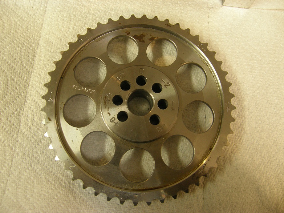
This is a spare Rollmaster timing gear that I had in my parts box. I was interested in using Rollmaster sets because they come with the good Iwis timing chain, and I also have one on my 428CJ dyno mule, which is the engine I'm planning to test with next weekend. The original hole for the cam pin is marked with a "0" on the gear now, and six more holes have been put in the gear. The mark above each hole represents where that hole is in terms of timing, as compared to the original hole. All marks are in crank degrees, not cam degrees. Assuming that you are at TDC on the number one cylinder, to use straight up cam timing you would put the tooth marked with the factory dimple straight down, and put the cam pin in the hole marked zero. To advance the cam 4 degrees, you would put the tooth that is marked "+4" straight down, and put the cam pin in the hole marked "+4". All other cam degreeing is done the same way. This gear is set up so that you can advance or retard the cam plus or minus 6 crank degrees, in 2 degree increments.
With one of these Rollmaster sets, and many other sets of course, you also can advance or retard the cam timing at the crank gear. The way I would envision using this setup when building an engine is to set the cam up degreed the way you think you'd want it (whether advanced or retarded, or straight up), using the crank gear. Then, you could fine tune the cam timing using the cam gear, through the opening in the timing cover, after the engine was all put together. You'd just have to pull the water pump, and then pull the front plate on the timing cover, to change your cam timing.
When I first got going on this project last weekend, I pulled out the timing sets that I had on hand and started looking at them in detail. I found quite a few differences in critical dimensions on these things. Here's a picture of the four upper timing gears that I had on hand:
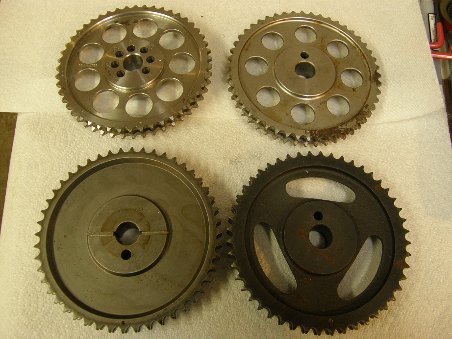
On the upper left is the Rollmaster, the upper right gear is from some outfit called JR Performance, the lower right is the standard performance Cloyes gear, and the lower left is the top end Cloyes gear. Both the Cloyes sets, and the Rollmaster set, come with the good Iwis timing chain; the JR Performance set came with a chain from India. (Danger, Will Robinson LOL!) One thing that struck me right off the bat was that on three of the gears, the mark on the outside cam tooth was on the opposite side of the center hole as the cam pin, but on the high end Cloyes set, the mark on the gear, and the cam pin, are on the same side of the center hole. I wonder why they did that? The motor won't care, but the high end Cloyes gear seems very unconventional.
After getting these things out I started measuring them. I have a set of plug gauges in 0.0005" diameter increments to measure the center hole and the cam pin hole. Both the Cloyes gears measured a perfect 0.7500", just barely allowing my pin to go through the center hole. The JR Performance gear measured 0.749", and the Rollmaster measured 0.7485"! Also, looking inside the Rollmaster center hole it was clear that it was an interference fit on the cam, on whichever engine I'd installed it on. There were lines and burrs on that inside diameter. Since I was going to have to make a fixture to hold these things, it was clear that the fixture wasn't going to fit both the Cloyes and the Rollmaster gears. In the end I solved this problem by using a removable pin as the center post of the fixture, and grinding the OD of the pin down a couple of thousandths so it would fit inside the Rollmaster gear. But again I have to wonder about the rationale at Rollmaster to make the center hole a press fit, rather than a slip fit like the Cloyes gears are. Maybe a more secure connection to the cam or something?
The situation was similar when I started measuring the cam pin holes in the gears. Both Cloyes gears and the JR gear measured 0.3120" for the cam pin hole diameter, but the Rollmaster measured 0.3110". I had a billet roller cam handy on the bench and it measured exactly 0.3125", which I think is what it is supposed to measure. So it appears that the cam pin should be a press into the top timing gear, but it was much more of a press on the Rollmaster gear than on the others. Again, I don't know why.
After figuring all this out I wanted to confirm that these measurements were consistent on the Rollmaster sets, so I gave Doug Garifo at Precision Oil Pumps a call and had him send me a new Rollmaster set, just so I could check it; it is supposed to arrive this week. In the meantime, I got to work designing a fixture to hold the top timing gear while I machined it. Since the dyno mule I'll be running the timing cover on already has a Rollmaster set in it, I decided to do the Rollmaster fixture first. Here's a picture of it, with the gear installed and already machined, on my smaller CNC machine:
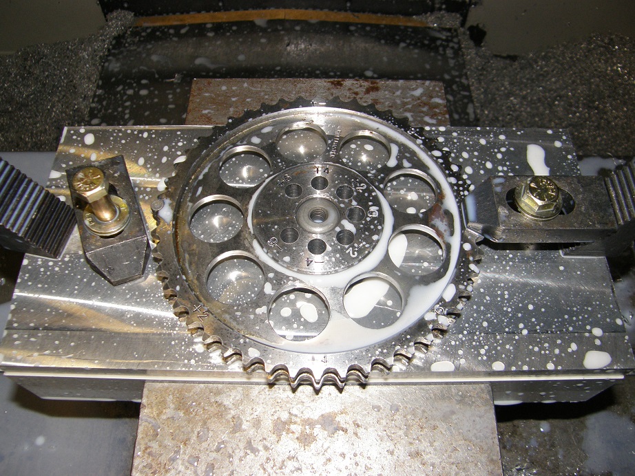
Those little clamps hold the gear in place while I'm machining it, and the gear itself indexes on a pin in the center hole, and a 1/4" pin that is installed on the left side of the gear, to mesh with one particular pair of teeth.
Next on my list is to do the high end Cloyes gear. I think I'm probably not going to do the standard Cloyes gear, because the timing gear itself is cast iron rather than steel, and I'm a little concerned that putting all these extra holes in the middle of the gear might weaken the cast iron gear too much. What do you guys think? I'm much less worried about the top end Cloyes and the Rollmaster gears, because they are steel, not cast iron. The Cloyes gear also offers the opportunity for me to drill and tap a few holes in the middle, so that I could install a cam sensor target on this gear. Then I could put a matching hole in the front plate of the timing cover, and offer anyone going with EFI an easy route to installing a cam sensor. That would be pretty cool, I think...
Over the Thanksgiving weekend I plan to get my 428CJ back on the dyno, probably with a different set of headers along with one of these timing sets and timing covers, and then run some back to back dyno pulls by changing the cam timing through the whole range of of adjustability that this modified top gear offers. They always say that you will improve low end torque by advancing the cam, and improve high end horsepower by retarding it. We will see next weekend if that holds true on this particular engine. I will post the results in the technical section next weekend, barring any unforeseen problems.


