Author Topic: Intake Manifold Design - Forced Induction (MEL)  (Read 3822 times)

0 Members and 1 Guest are viewing this topic.

FrozenMerc

  • Full Member
  • ***
  • Posts: 169
    • View Profile
Intake Manifold Design - Forced Induction (MEL)
« on: September 27, 2021, 02:24:06 PM »
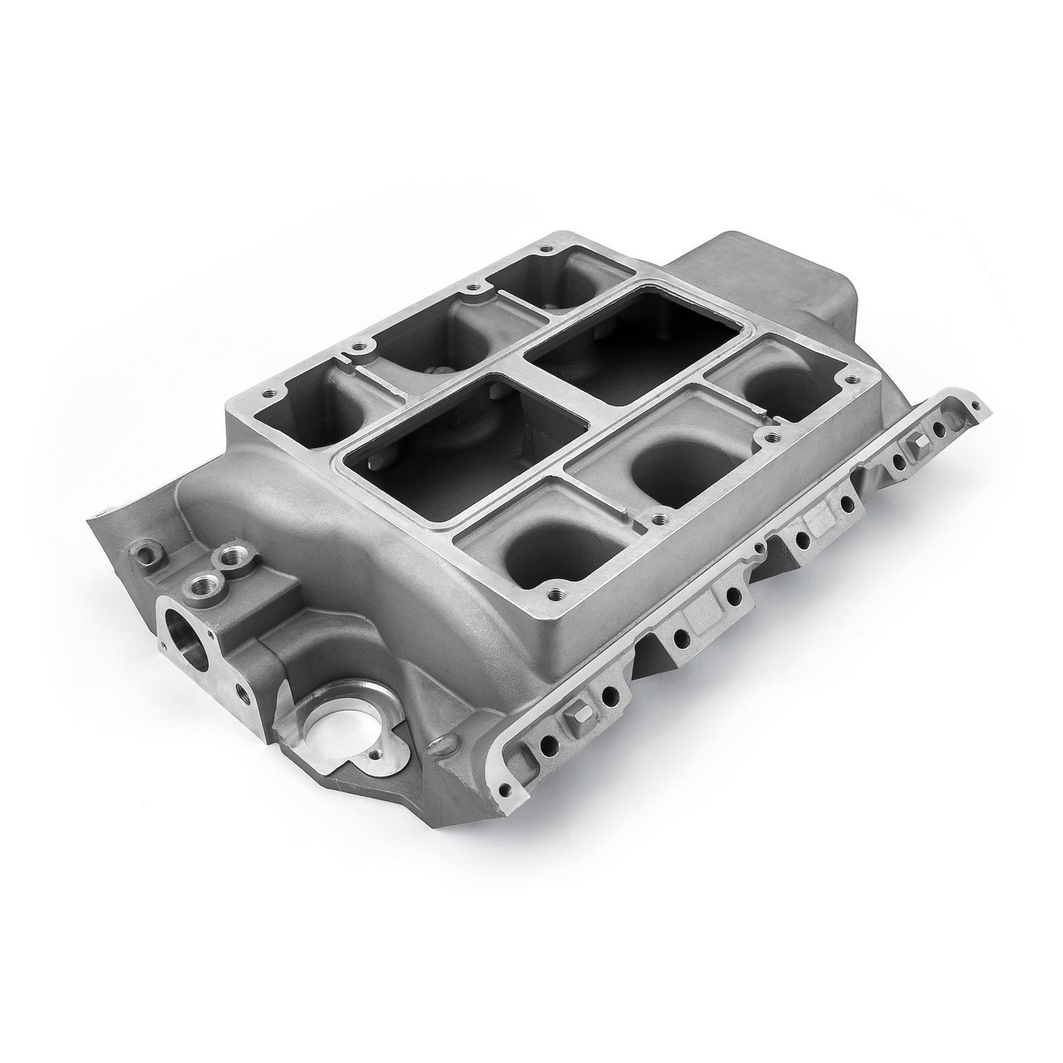
A bit off topic, but I would like some opinions from the brain trust on here.  4 or 5 years ago, I got my hands on a 430 MEL core, a 6-71 blower, and an old Weiand Intake manifold to pair the two together.  However, it quickly became obvious the Weiand intake was a race only piece that would require things such as a remote thermostat, relocation of the distributor, and crank breather.  It only had minimal provisions for coolant passages that I felt would not work well on a street motor, and to be clear, my intention was for the motor to be 100% street functional (idling in traffic, 75 mph sustained interstates, etc.).  After researching relocating the distributor and doing the other modifications that it would require to make the Weiand work, I came to the conclusion that it would likely be easier to build the intake manifold I needed instead.

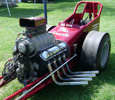
Excuse the dirty engine...


Being the good little engineer that I am, I took the Weiand and made a CAD model of it in UG.  I then started another model that had all the features I wanted, including clearance for the stock distributor, the thermostat in the stock location, better water passages, relocation of blow-off valve, etc.  I have an image of that model below.


Well, that was about 3.5 years ago, life happened, new job, moved across the country, couldn't sell the old house and shop, blah, blah, blah.  Long story short, I am ready to get back on this project by getting a 3D printed plastic model made for fit-up, flow testing, etc.  But before I do, the design of the plenum has been bugging me.  The Weiand was completely open in the center (see cross section of the CAD model below), resulting a very large plenum.  I think this probably worked fine on a drag car that was either idling or at WOT with a healthy amount of boost, but I am concerned that at part throttle operation low boost (or no boost), this is less than optimal. 


What do you guys that have played with forced induction applications think?  My thoughts are leaning towards redesigning it so the plenum is no wider than the opening in the bottom of the 6-71.  This would increase the individual cylinder runner length significantly, and hopefully smooth out the flow.  More along the lines of an FE 6-71 intake.


Not that it matters as I want this to be somewhat universal for any street driven application, but the plan / specs for this motor are as follows.

1958 430 MEL
Offset ground crank to BBC journal size.  4.1" stroke (or as close as possible)
4.35" bore
6-71 Blower, up to 12 psi boost
8:1 compression (most likely custom pistons, although 427 BBC flat-tops will get me close)
Should be right around 485 ci all said and done.  Street friendly tune concentrating on a big, broad torque curve.
I am not sure what it is going in, but most likely something big and heavy.

Finally, The Weiand's intended purpose...

« Last Edit: September 27, 2021, 02:39:38 PM by FrozenMerc »

TomP

  • Hero Member
  • *****
  • Posts: 874
    • View Profile
Re: Intake Manifold Design - Forced Induction (MEL)
« Reply #1 on: September 27, 2021, 10:51:27 PM »
Very rare intake there don't cut it up. Longer runners would be better, for a lower height they used a big box with one large hole in the top and eight smaller holes in the sides.

jayb

  • Administrator
  • Hero Member
  • *****
  • Posts: 7406
    • View Profile
    • FE Power
Re: Intake Manifold Design - Forced Induction (MEL)
« Reply #2 on: September 28, 2021, 10:03:00 AM »
+1, no runner length will kill low end torque.  It will be bad enough with the short runners you are stuck with when leaving the center of the manifold open for the blower.  Hopefully it will come up on boost fast and you won't notice the issue.  In the drag car you'd never notice the issue because you would leave the line under boost, but on the street it may be a different story.
Jay Brown
- 1969 Mach 1, Drag Week 2005 Winner NA/BB, 511" FE (10.60s @ 129); Drag Week 2007 Runner-Up PA/BB, 490" Supercharged FE (9.35 @ 151)
- 1964 Ford Galaxie, Drag Week 2009 Winner Modified NA (9.50s @ 143), 585" SOHC
- 1969 Shelby Clone, Drag Week 2015 Winner Modified NA (Average 8.98 @ 149), 585" SOHC


cjshaker

  • Hero Member
  • *****
  • Posts: 4460
    • View Profile
Re: Intake Manifold Design - Forced Induction (MEL)
« Reply #3 on: September 28, 2021, 11:21:55 AM »
You could enlarge the ports on that Weiand, then slide tubes up inside the plenum and have them welded in, essentially making the runners that you need. Or you could "notch" the opening, have the ports flanged, and simply sandwiched between the head and intake. It wouldn't require any changes or cutting to the outside, and nothing would look different. Just an idea.

As for the water ports, they would flow much better with better fittings, or you could enlarge the port holes. Not sure if there's enough meat there to do that or not. You'd be surprised how much water would flow when you have 2 ports flowing. Seen lots of big HP cars on Drag Week doing exactly that, and they seem to work fine with a good pump.

Cool piece though. Royce needs that for his FED.
Doug Smith


'69 R-code Mach 1, 427 MR, 2x4, Jerico, 4.30 Locker
'70 F-350 390
'55 Ford Customline 2dr
'37 Ford Coupe

FrozenMerc

  • Full Member
  • ***
  • Posts: 169
    • View Profile
Re: Intake Manifold Design - Forced Induction (MEL)
« Reply #4 on: September 28, 2021, 12:21:19 PM »
I am definitely not going to cut up or really even touch the Weiand.  That is too rare and too nice of a piece to mess with.  Tom and Jay, you confirmed what I was thinking.  Time to go back to the CAD board and draw something up with longer runners and a smaller center plenum.  I don't think it will be too difficult, just take a few hours.  Thanks for the insight, everyone.  If there is interest, I will keep this updated as things progress.  I have got to put this Corn Binder back together first and then it is on to the MEL.


« Last Edit: September 29, 2021, 03:14:54 PM by FrozenMerc »

Dumpling

  • Sr. Member
  • ****
  • Posts: 394
    • View Profile
Re: Intake Manifold Design - Forced Induction (MEL)
« Reply #5 on: September 28, 2021, 01:24:46 PM »
Did they ever make a 2x4 intake for the MEL?
If there's one available, make an adapter to mount on top of it, open plenum under the blower feeding into the carb openings.  That would give you the runner length and probably address the water and distributor issue too. Would end up setting the blower higher though.
« Last Edit: September 28, 2021, 02:06:44 PM by Dumpling »

67xr7cat

  • Sr. Member
  • ****
  • Posts: 315
    • View Profile
Re: Intake Manifold Design - Forced Induction (MEL)
« Reply #6 on: September 28, 2021, 11:14:17 PM »
The MEL and 385 series (429/460) both have a 4.9" bore spacing.  Guys have adapted intakes from a 460 to the MEL. Was common back in the day when putting a blower on a 460 to use a tunnel ram intake with a plate fashioned to attach the blower. Made for a bit high deal, but cleared the dizzy just fine.  Also the MEL and 460 cranks are pretty close.  Guys have used the stroker 460 cranks in the MEL.  Offset grinding the MEL crank is fine, but if you want a bigger stroke or a forged crank doing the mods to make the 460 crank work is the way to go.

FrozenMerc

  • Full Member
  • ***
  • Posts: 169
    • View Profile
Re: Intake Manifold Design - Forced Induction (MEL)
« Reply #7 on: September 29, 2021, 01:43:55 PM »
Did they ever make a 2x4 intake for the MEL?
If there's one available, make an adapter to mount on top of it, open plenum under the blower feeding into the carb openings.  That would give you the runner length and probably address the water and distributor issue too. Would end up setting the blower higher though.

As far as I know, there was never a 2x4 intake for the MEL.  3x2 and 1x4 from the factory (all cast iron), and a few aftermarket oddities such as the Weiand blower intake and 6x2 and 8x2 log set ups.

The MEL and 385 series (429/460) both have a 4.9" bore spacing.  Guys have adapted intakes from a 460 to the MEL. Was common back in the day when putting a blower on a 460 to use a tunnel ram intake with a plate fashioned to attach the blower. Made for a bit high deal, but cleared the dizzy just fine.  Also the MEL and 460 cranks are pretty close.  Guys have used the stroker 460 cranks in the MEL.  Offset grinding the MEL crank is fine, but if you want a bigger stroke or a forged crank doing the mods to make the 460 crank work is the way to go.

I initially looked into 385 compatibility.  Supposedly someone was making a set of adaptors to go from the MEL to 385 series intake about 10 or 12 years ago.  The photos I could find led to questions that did not have a good solution.  Mainly dealing with the port shape (oval - 385, rectangle - MEL), and the coolant cross over (front on the 385, rear on MEL).  In the end, I just liked the thought of doing my own intake better.  More issues could be resolved in one package rather then solving 2 and creating 4 more, even if it cost more.

I also thought about the 460 crank, Kasse and Royce obviously did it quite effectively on the Engine Masters MEL.   However, I would still have to buy a 460 crank (aftermarket or otherwise) and have it machined.  I already have the MEL crank and it still needs to be machined.  I figured the machining cost was going to be a wash between the two cranks, so I decided I would start out with what I already have. 
« Last Edit: September 29, 2021, 01:59:35 PM by FrozenMerc »

Royce

  • Hero Member
  • *****
  • Posts: 777
    • View Profile
Re: Intake Manifold Design - Forced Induction (MEL)
« Reply #8 on: September 29, 2021, 03:57:42 PM »
Jay can fix you up with adapter to put a 460 intake on a MEL. He has one on a CNC program.  It requires some re-plumbing  of the coolant but nothing too radical 

Up to about 5500 - 6000 I would trust the Stock MEL crank. I offset ground mine to 4.124 on a 524 inch and on a 475 inch, offset to 4".   The 475 never gave any trouble , but I am limiting the long stroke to 5500. I did these before the 460 crank idea came along..

 All MEL stock intakes suck.. Even the Super Marauder
1955 Thunderbird Competition Coupe Altered Chassis "War Bird" 383 Lincoln Y block 520 hp
1955 Thunderbird 292 275 hp Y Block
1956 Ford Victoria 292 Y block

1957 Mercury 2dr Wagon "Battle Wagon" drag car 
1957 Thunderbird Glass body Tube Chassis drag car 333 cu in 500 hp Ford Y block
1961 Starliner 390/375 clone
1965 GT40 tribute w/FE
1966 Falcon Pro Touring project
Kaase Boss 547. 840 HP 698 Torque  pump gas
1992 BMW V-12 5.0
2001 Lincoln 5.4 4 cam.
1968 Cougar XR7

pbf777

  • Sr. Member
  • ****
  • Posts: 490
    • View Profile
Re: Intake Manifold Design - Forced Induction (MEL)
« Reply #9 on: September 29, 2021, 04:29:55 PM »
.............3x2 and 1x4 from the factory (all cast iron),.............

     Just a note: the 3x2 factory "Super Marauder" intake was aluminum.    ;)

     There also is the aluminum Edelbrock L300 3x2, but vs. the Holley 2300's as on the S.M. version, I've seen them drilled for either the 4-bolt small-base 2V Rockchesters or the 3-bolt Holley 2100's & Stromberg 94/97's.

     This intake presents good runner lengths, and could be converted into a blower intake in the typical process of the addition of an adapter plate with machining and welding, though the blower, without intentional spacing would be quite low perhaps complicating the distributor fixturing; but does have the advantages of being flat in the plenum presentation which aids in the endeavor vs. with a rake angle, and does exhibit the water passage from the rear. 

     Scott.   

frnkeore

  • Hero Member
  • *****
  • Posts: 1136
    • View Profile
Re: Intake Manifold Design - Forced Induction (MEL)
« Reply #10 on: September 30, 2021, 02:17:13 AM »
You may be over thinking this, a little.

I have some personal experience with old blower manifolds and street driving. My best friend had this car and he and I did all the work on it, frame body, drive train and engine. It was a 326 Olds, with Herbert roller cam and a 471 with dual AFB's. There weren't any dividers for the ports, just a open hole, for each pair of ports but, because the heads aren't as far a part as the MEL, the plenum was a little smaller.

It weighed about 2200 and with the smaller engine, it no flat spots and a smooth transition from idle to any speed, part throttle or WOT. Instant torque! It actually got good gas mileage, too. I think that was because the rotors helped with atomization of the fuel.

Now, at part throttle, on a dyno, you might be able to see a difference, with a well designed manifold but, on the street, I believe you would be hard pressed to tell in by the seat of your pants. Once the plenum becomes pressurized, at any level (and that does not take long), the A/F is at the valve, ready to serve the cylinder. Remember a pressurized vessel, has equal pressure in all directions.

I would agree that the water ports are small and look like 3/8 pipe, to me but, it looks like there is enough room on the boss to take them to 1/2 pipe. I think 1/2 would work for anything but sustain HARD pulls. Back in the 60's and early 70's, there were street driven cars with 671, that ran with a pair of Jabsco 12V water pumps (like for RV water systems). They seemed to run ok at street level driving, in SoCal but, I wasn't associated with them so, I can't confirm that they were trouble free. Georges coupe had the std Olds pump.

The biggest thing, as I see it, is making a 90° or a offset drive, for the dist.
« Last Edit: September 30, 2021, 02:21:18 AM by frnkeore »
Frank

cjshaker

  • Hero Member
  • *****
  • Posts: 4460
    • View Profile
Re: Intake Manifold Design - Forced Induction (MEL)
« Reply #11 on: September 30, 2021, 06:44:15 AM »
Frank, that had to be the bitchinist car in the valley!

Sorry, I couldn't resist the obvious Milner comparison.  ;)
Cool car.
Doug Smith


'69 R-code Mach 1, 427 MR, 2x4, Jerico, 4.30 Locker
'70 F-350 390
'55 Ford Customline 2dr
'37 Ford Coupe

frnkeore

  • Hero Member
  • *****
  • Posts: 1136
    • View Profile
Re: Intake Manifold Design - Forced Induction (MEL)
« Reply #12 on: September 30, 2021, 11:44:53 AM »
It was and we were almost, always stopped by the cops when we took it out. The HR picture, was in the Nov '64 issue and a preview for the Orange County Car and Boat Show, held that Nov.

Although I don't have any pictures of it with my 427, it is the the car that I put my LR in, before he sold it and I went formula car racing. He put the Olds in a flat bottom boat.
Frank

1964Fastback

  • Jr. Member
  • **
  • Posts: 92
    • View Profile
Re: Intake Manifold Design - Forced Induction (MEL)
« Reply #13 on: September 30, 2021, 12:38:56 PM »
A bunch of us were talking about American Graffiti the day after it was shown on TV for the first time, before class.  A friend of mine, laid back and a bit of a stoner said, "Man, a deuce coupe and a '55 Chevy drag racing at dawn!  I was just born too late!"  At the time, anyway, I had to agree with him.  :)

Pat
1964 Galaxie 500 2 dr Fastback, 390, 4 speed, Indianapolis Indiana

pbf777

  • Sr. Member
  • ****
  • Posts: 490
    • View Profile
Re: Intake Manifold Design - Forced Induction (MEL)
« Reply #14 on: September 30, 2021, 12:40:23 PM »
What do you guys that have played with forced induction applications think?  My thoughts are leaning towards redesigning it so the plenum is no wider than the opening in the bottom of the 6-71.  This would increase the individual cylinder runner length significantly, and hopefully smooth out the flow.  More along the lines of an FE 6-71 intake.


     Backing up a little; if the intention is to manufacture an intake of your own design, then yes, I would incorporate similar under blower plenum to port runner transition as presented in the photo of the FE example.    :)

     But I'm not so sure that with the longer port runners torque increases would truly be the greatest benefit, as stated by another previously this is a positive displacement blower geared to the crank, so boost will come-up rather quickly with throttle opening even at lower revolutions; but rather I think the greater value would be to aid in the control of fuel drop-out, this being promoted due to the otherwise rather large box plenum area, that although the fuel may have been well mixed as passing thru the blower, without better directional coercement and considering the necessity to operate with a generally otherwise considered overly rich mixture, excessive unappreciated fuel puddling at the lower velocities is likely.    :(

     Also while engineering your manifold realize that typically over the decades it has been noted that there is a tendency for the fuel charge to present leaner mixtures toward the front and getting progressively richer as approaching the rear; this generally being attributed to the helix twist in the rotors resulting in their progressive displacement of area in their length. Remember, this was not a concern by Detroit Diesel in the original application as no fuel (diesel) was intended to pass thru the blower (direct in cylinder injection) not to mention the convoluted pathway from the blower discharge to the air box position on the side of the block to feed the cylinders port openings (two-stroke!   :o  ) negated any such considerations; though still, due to reversion effects the air boxes were fitted with drains to remove the accumulation of oil and fuel liquid. The simplest solution to attempt to equalize the cylinder to cylinder fuel mixtures has generally been to move the blowers' mounting forward on the engine, when and if other concerns (what distributor?    ::)  ) in the fitment permit such; this somewhat akin to the adjustable/sliding carburetor spacer plates this allowing the carburetor to be moved forward & back to find the position providing the best performance.   ???

     As a side note: if one were going to have a billet crankshaft made for their MEL or Lima 385 motor, for an aggressive blower application, consider looking at the 1967-'68 front timing covers (for seal application) with the crankshaft snout mounted power steering pumps (just mimic the P.S. assembly's drive hub O.D.), as this engineering would permit a quite greater diameter crank-snout providing better support particularly considering the length in these engine applications!    8)

     Scott.

« Last Edit: September 30, 2021, 12:45:10 PM by pbf777 »