Show Posts

This section allows you to view all posts made by this member. Note that you can only see posts made in areas you currently have access to.


Messages - FrozenMerc

Pages: 1 ... 3 4 [5] 6 7 ... 12
61
FE Technical Forum / Re: Fuel Efficient Build---352 or 351W
« on: March 04, 2022, 12:45:44 PM »
I would be willing to bet a box of doughnuts that swapping the C6 for an AOD would get you from 13-16 to 16-19 mpg, unless you have a really tall rear end gear.  The nice part is it is a bolt in, but looking at the numbers, is it worth it?

$3K for a trans swap, yes you can probably do it cheaper, but lets say you buy a nice, new AOD trans from somewhere and a few other pieces and widgets you end up with about $3K into the swap. 

The AOD get's you 3 extra mpg on average.  At $3 per gallon, it will take about 90,000 miles of driving to pay off the $3K spent on the swap, factor in inflation and net present value over the next 4.5 years that it takes for you to rack up 90K miles, and it probably isn't worth it. 

But then again, NONE of the things we do to these old cars on this board are generally worth it from a pure accounting standpoint.  It is just for the Fun, and it is arguably better than spending the cash on hookers and blow.

62
FE Technical Forum / Re: Fuel Efficient Build---352 or 351W
« on: March 03, 2022, 02:18:00 PM »
I have done both.  In fact, they were very similar builds.  Both engines have a +0.030 over bore, similar cams, 600 cfm Holley's, approx 9:1 compression, etc.  The only real difference is the 352 got aluminum Edelbrock heads, and the 351W used the stock '78 LTD smog heads.  The 352 is in my '62 Merc Monterey wagon, backed by a non-lock-up AOD and 3.6 rear axle.  The 351W is in a '51 F-1, backed by a M5R2 5 spd, and 3.08 rear axle.  Tire size is real similar between the two.

The '62 will pull down 15 mpg cruising at 65 mph.  The '51 will also pull 15 mpg on the highway.  You could argue 352 is the more efficient motor of the two since the wagon weighs a good 1000 lbs more than the little pickup.  I think the wagon probably has better aerodynamics, but it probably isn't all that great of a difference. 

That said, I also built a decent 300 6.  Full length split header, Comp 270-H cam, Offy Dual-Port Intake and Holley 600 cfm carb, flat top slugs that brought the compression up to about 9:1.  Backed by an AOD in a '83 Bullnose, it would pull a consistent 18 mpg down on the highway at that magic 65 mph mark.

If I was concerned about mileage, I sure as heck wouldn't build something around a C6.  Great, durable transmission, but terribly inefficient.  Manual transmission with overdrive would be the best way to go.

As JimNolan said, target a 1800 to 2000 rpm cruising range.  Build as much compression into it as you can get away with, and cam it to have the torque peak in the 2200-2500 rpm range and be prepared for the thing to be out of wind around 4500 rpms.  Optimize the build so you can maximize the area under the entire torque curve, and dial in you AFR's across the cruising range.


63
FE Technical Forum / Re: Headers (another one for the rocket scientists)
« on: February 16, 2022, 01:44:38 PM »
When it comes to this topic, I cut my teeth in the 2-stroke world were pipe length, expansion chambers, power valves, etc can all have very significant effects on not only peak power, but power and torque over the entire operating range.  I have found that 4 strokes, (especially the large displacement, slow reving v8's that we love on this board) have a much higher tolerance for bad exhaust system design.  This is primarily due to more power being lost due to exhaust system back pressure than gained from scavenging, so reducing back pressure is typically the better way to free up more power.  The turbo guys are particularly aware of this as they can generate back pressures of 50+ psi at the piston.  But as far as tuning your pipe length to generate a scavenging effect alla 2 strokes, it is very difficult to make it happen over more than a couple hundred RPM range.  This is due to the nature of pressure pulse frequency and how the pulses merge and act together within the pipes.  This effort is probably worth your time on a race car that operates in a very narrow RPM band, but on street cars that operate from 800 to 5500+ rpms, the juice just isn't worth the squeeze.  As Jay pointed out, the best thing to do is keep your back pressure minimized, via smooth bends and correctly sized pipe for the flow requirements.


64
Non-FE Discussion Forum / Re: Classic car title
« on: January 10, 2022, 01:01:25 PM »
Go to your local DMV and ask.  It is likely alot easier than you think. 

I have done it a number of times in Minnesota, with no problems.  The key is to have the right documentation, and they will tell you exactly what you need.

65
FE Technical Forum / Re: FE Head Temp
« on: January 03, 2022, 02:15:43 PM »
I can't speak to FE's, but I have done this exercise on smaller engines (single, V-Twin, and Inline Twin two and four strokes) in the past.  I would drill and tap dozens of holes into the water jackets around the cylinder and throughout the heads and install thermocouples.  It wasn't unusual to have 12 to 16 thermocouples mounted in the cylinder, and another 8 to 12 in the head on these engines.  This was almost always done on prototype engines, or new designs to make sure there wasn't any problems during initial run-in and fuel mapping.  Generally speaking, there wouldn't be more than a few degrees difference between the thermocouples, once the engine was up to temp.  Warm up would show a bit of difference, especially with the thermostat closed. 

The one engine that would show a large temperature difference would be the direct injected two strokes.  The fuel was sprayed through a window in the piston towards the transfer ports.  The spray pattern would hit the opposite side and keep that cylinder wall considerably cooler.   Took a looonnnng time to figure out how to properly cool the piston on that design to keep it from splitting along the window and sticking in the bore. 


66
Non-FE Discussion Forum / Re: Torque converter stall speed vs vehicle
« on: October 27, 2021, 01:33:20 PM »
I am not a guru by any means, but I can offer another set of data points.

1962 Mercury Monterey Wagon - Broader AOD conversion behind the 352. - Stall: approx. 1800 rpms, perfect for highway cruising.
352: 325 hp, 375 ft-lbs of torque
9.5:1, Elgin 966P cam
3.6:1 9 inch rear axle, 28" tires

1975 Ford F250 Camper Special - Broader AOD conversion behind the 390.  Stall: approx. 2400 rpms, bad for highway cruising as the cruise rpm is below the stall speed, and it heats the fluid due to the excess slip.
390:  360 - 380 hp, 400 - 425 ft-lbs
9.5:1, Howards dual pattern cam.
4.11:1 Dana 60 axle, 36" tires

As far as I know, the torque convertors were near identical for these two builds.  They both were "as tight as possible" in order to have good highway manners since the AOD's lock-up feature was deleted.  The bellhousing on the AOD to FE conversion limits the convertors diameter and makes getting a low stall convertor behind a high torque motor (or heavy vehicle) difficult.

67
I don't think choking the 6-71 through any more of a funnel than absolutely necessary is wise.  Roots blowers are positive displacement type blowers that create air flow only, and rely on downstream restrictions to create the manifold pressure.  Having a major restriction between the manifold and blower seems like a recipe to make an already in-efficient air pump even worse, and do nothing to increase the charge air density, which is what we are after in the long run.  Part of the reason why I am leaning towards a new manifold, rather than trying to modify an existing one.

No doubt a centrifugal supercharger would be easier, and probably better for max power efforts, especially if an intercooler could be deployed, but I also am going for a specific look.  Even though there a few examples of some damn good looking Paxton / McCullochs on MEL's out there.


68
     Backing up a little; if the intention is to manufacture an intake of your own design, then yes, I would incorporate similar under blower plenum to port runner transition as presented in the photo of the FE example.    :)

     But I'm not so sure that with the longer port runners torque increases would truly be the greatest benefit, as stated by another previously this is a positive displacement blower geared to the crank, so boost will come-up rather quickly with throttle opening even at lower revolutions; but rather I think the greater value would be to aid in the control of fuel drop-out, this being promoted due to the otherwise rather large box plenum area, that although the fuel may have been well mixed as passing thru the blower, without better directional coercement and considering the necessity to operate with a generally otherwise considered overly rich mixture, excessive unappreciated fuel puddling at the lower velocities is likely.    :(

     Also while engineering your manifold realize that typically over the decades it has been noted that there is a tendency for the fuel charge to present leaner mixtures toward the front and getting progressively richer as approaching the rear; this generally being attributed to the helix twist in the rotors resulting in their progressive displacement of area in their length. Remember, this was not a concern by Detroit Diesel in the original application as no fuel (diesel) was intended to pass thru the blower (direct in cylinder injection) not to mention the convoluted pathway from the blower discharge to the air box position on the side of the block to feed the cylinders port openings (two-stroke!   :o  
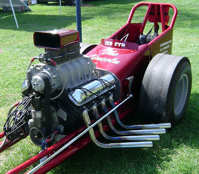
) negated any such considerations; though still, due to reversion effects the air boxes were fitted with drains to remove the accumulation of oil and fuel liquid. The simplest solution to attempt to equalize the cylinder to cylinder fuel mixtures has generally been to move the blowers' mounting forward on the engine, when and if other concerns (what distributor?    ::)  ) in the fitment permit such; this somewhat akin to the adjustable/sliding carburetor spacer plates this allowing the carburetor to be moved forward & back to find the position providing the best performance.   ???

     As a side note: if one were going to have a billet crankshaft made for their MEL or Lima 385 motor, for an aggressive blower application, consider looking at the 1967-'68 front timing covers (for seal application) with the crankshaft snout mounted power steering pumps (just mimic the P.S. assembly's drive hub O.D.), as this engineering would permit a quite greater diameter crank-snout providing better support particularly considering the length in these engine applications!    8)

     Scott.

All Valid points, Scott.  I was concerned about fuel puddling, and equal fuel distribution to the front cylinders.  That is part of what made me hesitate on just copying the Weiand design and ask for opinions on here.  Even in my initial design, the front cylinder port was somewhat blocked by the thermostat housing, and I am especially concerned with that one going lean, not a good thing in a boosted application.

All told, the easy thing to do would be to stick with the stock 4 barrel manifold, add a throttle body injection unit, and go with a belt driven centrifugal supercharger.  But that didn't sound like as much fun.... :o

69
You may be over thinking this, a little.

The biggest thing, as I see it, is making a 90° or a offset drive, for the dist.

Your not the first to accuse me of such.  Something about not being able to find a tree since this damn forest keeps getting in the way.

I did alot of research on offset or 90 deg drive distributors.  Honestly, going to a remote electric water pump, and adapting a flathead crab style distributor to the timing cover would probably be the simplest.  Blower Drive belt clearance could be interesting, but I think doable.

Very Cool car, Thanks for the insight and experience with a similar setup.


70
Jay can fix you up with adapter to put a 460 intake on a MEL. He has one on a CNC program.  It requires some re-plumbing  of the coolant but nothing too radical 

Up to about 5500 - 6000 I would trust the Stock MEL crank. I offset ground mine to 4.124 on a 524 inch and on a 475 inch, offset to 4".   The 475 never gave any trouble , but I am limiting the long stroke to 5500. I did these before the 460 crank idea came along..

 All MEL stock intakes suck.. Even the Super Marauder

I have no plans to exceed 6000 rpms.  No intention to build an all out max horsepower effort.  The goal is for a reliable bruiser.  I know there are much easier ways to do that (445 FE, 460 based  whatever, Cummins, etc.), but I like taking the road less travelled.

71
Did they ever make a 2x4 intake for the MEL?
If there's one available, make an adapter to mount on top of it, open plenum under the blower feeding into the carb openings.  That would give you the runner length and probably address the water and distributor issue too. Would end up setting the blower higher though.

As far as I know, there was never a 2x4 intake for the MEL.  3x2 and 1x4 from the factory (all cast iron), and a few aftermarket oddities such as the Weiand blower intake and 6x2 and 8x2 log set ups.

The MEL and 385 series (429/460) both have a 4.9" bore spacing.  Guys have adapted intakes from a 460 to the MEL. Was common back in the day when putting a blower on a 460 to use a tunnel ram intake with a plate fashioned to attach the blower. Made for a bit high deal, but cleared the dizzy just fine.  Also the MEL and 460 cranks are pretty close.  Guys have used the stroker 460 cranks in the MEL.  Offset grinding the MEL crank is fine, but if you want a bigger stroke or a forged crank doing the mods to make the 460 crank work is the way to go.

I initially looked into 385 compatibility.  Supposedly someone was making a set of adaptors to go from the MEL to 385 series intake about 10 or 12 years ago.  The photos I could find led to questions that did not have a good solution.  Mainly dealing with the port shape (oval - 385, rectangle - MEL), and the coolant cross over (front on the 385, rear on MEL).  In the end, I just liked the thought of doing my own intake better.  More issues could be resolved in one package rather then solving 2 and creating 4 more, even if it cost more.

I also thought about the 460 crank, Kasse and Royce obviously did it quite effectively on the Engine Masters MEL.   However, I would still have to buy a 460 crank (aftermarket or otherwise) and have it machined.  I already have the MEL crank and it still needs to be machined.  I figured the machining cost was going to be a wash between the two cranks, so I decided I would start out with what I already have. 

72
I am definitely not going to cut up or really even touch the Weiand.  That is too rare and too nice of a piece to mess with.  Tom and Jay, you confirmed what I was thinking.  Time to go back to the CAD board and draw something up with longer runners and a smaller center plenum.  I don't think it will be too difficult, just take a few hours.  Thanks for the insight, everyone.  If there is interest, I will keep this updated as things progress.  I have got to put this Corn Binder back together first and then it is on to the MEL.


73
Non-FE Discussion Forum / Intake Manifold Design - Forced Induction (MEL)
« on: September 27, 2021, 02:24:06 PM »
A bit off topic, but I would like some opinions from the brain trust on here.  4 or 5 years ago, I got my hands on a 430 MEL core, a 6-71 blower, and an old Weiand Intake manifold to pair the two together.  However, it quickly became obvious the Weiand intake was a race only piece that would require things such as a remote thermostat, relocation of the distributor, and crank breather.  It only had minimal provisions for coolant passages that I felt would not work well on a street motor, and to be clear, my intention was for the motor to be 100% street functional (idling in traffic, 75 mph sustained interstates, etc.).  After researching relocating the distributor and doing the other modifications that it would require to make the Weiand work, I came to the conclusion that it would likely be easier to build the intake manifold I needed instead.

Excuse the dirty engine...


Being the good little engineer that I am, I took the Weiand and made a CAD model of it in UG.  I then started another model that had all the features I wanted, including clearance for the stock distributor, the thermostat in the stock location, better water passages, relocation of blow-off valve, etc.  I have an image of that model below.


Well, that was about 3.5 years ago, life happened, new job, moved across the country, couldn't sell the old house and shop, blah, blah, blah.  Long story short, I am ready to get back on this project by getting a 3D printed plastic model made for fit-up, flow testing, etc.  But before I do, the design of the plenum has been bugging me.  The Weiand was completely open in the center (see cross section of the CAD model below), resulting a very large plenum.  I think this probably worked fine on a drag car that was either idling or at WOT with a healthy amount of boost, but I am concerned that at part throttle operation low boost (or no boost), this is less than optimal. 


What do you guys that have played with forced induction applications think?  My thoughts are leaning towards redesigning it so the plenum is no wider than the opening in the bottom of the 6-71.  This would increase the individual cylinder runner length significantly, and hopefully smooth out the flow.  More along the lines of an FE 6-71 intake.


Not that it matters as I want this to be somewhat universal for any street driven application, but the plan / specs for this motor are as follows.

1958 430 MEL
Offset ground crank to BBC journal size.  4.1" stroke (or as close as possible)
4.35" bore
6-71 Blower, up to 12 psi boost
8:1 compression (most likely custom pistons, although 427 BBC flat-tops will get me close)
Should be right around 485 ci all said and done.  Street friendly tune concentrating on a big, broad torque curve.
I am not sure what it is going in, but most likely something big and heavy.

Finally, The Weiand's intended purpose...


74
FE Technical Forum / Re: OMG really?
« on: July 12, 2021, 11:55:29 AM »

75
FE Technical Forum / Re: frame off
« on: May 03, 2021, 12:57:06 PM »
Yep. Fire Wrench

Air chisel works too, if you don't have an Oxy-Acetylene setup.


Pages: 1 ... 3 4 [5] 6 7 ... 12