Its easy to overstate the importance of the weight of the reciprocating components. I think the reason that the C-6 is such a power hog is because of its internal friction, and the weight of the internal components is not as important. You can calculate the amount of power required to accelerate an object of specific mass at a known acceleration rate, so let's do that for a couple of flywheel examples.
First we need to know the flywheel weight and diameter. Let's use some realistic examples, say a 16 pound aluminum flywheel vs. a 40 pound steel flywheel. Both flywheels are 13" in diameter. In the English system of units we will be calculating each flywheel's moment of inertia in a unit called Slug-Feet. So, to start with we have to convert the flywheel's weight into its mass in Slugs, which means dividing the weight of the flywheel by the acceleration due to gravity (32.2 feet/sec^2). So for the aluminum flywheel we have 16/32.2, or 0.497 Slugs. For the steel flywheel we have 40/32.2, or 1.242 Slugs. Then, we need the radius of the center of mass of the flywheel. This is basically a radius where the mass on the outside of the radius equals the mass on the inside of the radius. Its kind of like center of gravity of an object, if that makes it more clear. For a perfect disc, the radius of the center of mass is 0.707 multiplied by the actual radius. For our flywheel, 0.707 * 6.5" is 4.595". However, the center of the flywheel is typically recessed a little so it weighs less, and there's a hole in the middle of course, so to try to be more accurate we're going to cheat the center of mass radius up to 5.0". Finally we will divide that number by 12 to get the units in feet, which is 0.417 feet.
Now we can calculate the moment of inertia, which is simply the mass in slugs multiplied by the radius of the center of mass squared. So, for the aluminum flywheel, this is 0.497 * 0.417 * 0.417, or 0.0864. For the steel flywheel, we have 1.242 * 0.417 * 0.417, or 0.216. Comparing these numbers, we can see that it will take 2.5 times the power to accelerate the steel flywheel compared to the aluminum flywheel. Of course, this is just the ratio of the weights of the two flywheels. But now that we have the moment of inertia for each flywheel, we can figure out exactly how much torque is required to accelerate the flywheels at a given rate.
Let's start with a high acceleration rate, say 1000 RPM (rotations per minute) per second. In order to use the moment of inertia calculation we have to convert this to radians per second^2 (radians per second per second). There are 6.28 radians in each revolution, so this is 6280 radians per minute per second. Divide by 60 and we have 104.67 radians per second^2. Multiply this by the moment of inertia and you get the torque in lb-ft required to accelerate the flywheel at this rate. So, for the aluminum flywheel this is 9.05 lb-ft, and for the steel flywheel this is 22.6 lb-ft. So, you will gain about 13.55 lb-ft of torque at the flywheel if you change from a steel flywheel to an aluminum flywheel and accelerate at 1000 RPM/sec.
Now let's do a lower acceleration rate, say 300 RPM per second, which is typical for a dyno pull. For 300 RPM per second the acceleration works out to 31.42 radians/sec^2. For the aluminum flywheel, torque to accelerate at this rate is 2.71 lb-ft, and for the steel flywheel the value is 6.79 lb-ft. So, on the dyno, if you swapped from a steel flywheel to an aluminum flywheel and ran your dyno pulls at 300 RPM/second, you would see about 4 lb-ft more torque.
Now having said all this, let's think about where the big inertia losses are inside a transmission. Remember that the bigger the diameter of the component, the larger the radius of the center of mass will be, and the more torque it will take to accelerate for a given mass. Obviously, a big torque converter is a relatively large diameter, heavy object, especially when filled with fluid, so going to a smaller diameter converter will take a big chunk out of the torque required. But how about the internals? Earlier in this thread there was some discussion of a 3 pound aluminum drum vs. a 9 pound steel drum. I don't know offhand what the diameter of a C-6 drum is, but I'm going to guess about 7", from measuring the outside of a C-6 that I have here. Doing the previous calculations and using 80% of the radius of the drum for the radius of the center of mass (again just an estimate, because most of the mass of the drum is at the outside), I come up with 1.59 lb-ft required to accelerate the heavy drum at 1000 RPM/second, and 0.53 lb-ft required for the light drum. So, swapping to the lightweight drum will get you about 1 lb-ft of torque when accelerating at 1000 RPM/second.
The key thing to note here is that the diameter of the component has an outsized effect on the torque required to accelerate it, because the radius of the center of mass of the component is squared in the equation. The internal components of the transmission, with the exception of the torque converter, are all relatively small in diameter. They just won't make a big difference. The same thing goes for harmonic balancers, crank journals, driveshafts, etc. The smaller the diameter of the driveline component, the less torque it will take to accelerate it. I look at gun-drilled axles, for example, and can't believe that there is any tangible benefit to gun drilling them, because the diameter of the removed material is so small.
In any case, the small diameter of the interior components of a transmission make me believe that lightening them up will not have a significant effect on power consumed by the trans, and that's why I think internal friction is the big issue with the C-6.
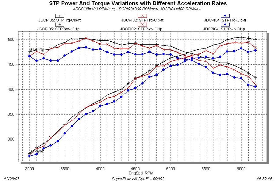
One more relevant piece of information is contained in the chart below. Here, I took the same engine on the dyno and accelerated it at three different rates, 100, 300, and 600 RPM/sec. Obviously, the slower you accelerate, the more power is available from the engine: