So, this tends to look kind of complicated, especially when all the options are considered. What I've put together in this post is two EFI systems, a "Street" version (inexpensive) and a "Race" version (expensive). The race version is essentially identical to what is on my 585" SOHC. We'll look at the street version first.
The street system assumes the use of a factory or MSD electronic distributor, and a coil (with or without MSD) to generate spark. It is also assumed to be a bank or batch fire system, not full sequential. Below is a basic wiring diagram for one of these systems. It is also shown on page 14 of the manual at this link:
http://www.msextra.com/doc/pdf/MS2V357_Hardware-3.4.pdf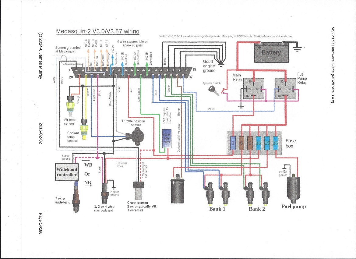
On this diagram, the connector shown with all the wires plugs into the Megasquirt 2 EFI box. This is set up as a bank-fire system; the fuel injectors are arranged in two banks, one of which fires once per crankshaft rotation. For our engines we would wire up four injectors for bank 1, and four for bank 2. There are only three external sensors required, the air temperature sensor, coolant temperature sensor, and throttle position sensor. A MAP sensor (Manifold Air Pressure) is also required, but it is built into the Megasquirt 2 EFI box; you just have to run a vacuum line from the engine to the EFI box. The PWM idle valve shown on the drawing can be ignored; you can just use the idle screw on the throttle body to set the idle. Also, a wideband O2 sensor is shown connected to the Megasquirt 2 EFI box, but this only has to be connected if you are logging data from the O2 sensor, or using the O2 sensor to provide feedback to the Megasquirt, so that the Megasquirt can try to adjust the fuel delivery to maintain a particular air/fuel ratio.
Here is a table showing the part requirements for this system, including links to all the required parts:
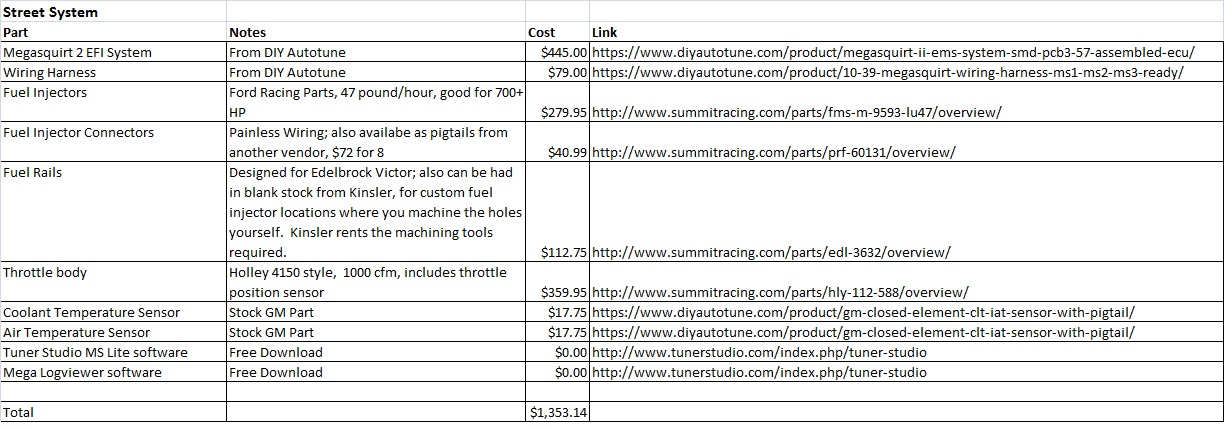
Couple of notes here. The wiring harness has to be assembled by the builder; this is just soldering the right wires to the right connectors. Just follow the schematic. The ignition system is assumed to be a stock Ford or MSD vane type distributor, with a coil. MSDs can also be triggered this way. The distributor wires connect into the crank sensor wires shown on the wiring diagram. The fuel rails shown in the list are Edelbrock parts designed to fit a Victor EFI manifold. The throttle body comes with the throttle position sensor, so you just have to connect the three wires from the EFI box to the connector on the throttle body. The air temperature sensor should mount in the air cleaner, or some other place where the air comes into the engine, but not under the throttle body. The coolant temperature sensor has to mount in a coolant passage, just like a sensor for a water temp gauge. Finally, the software to make this work is a free download called Tuner Studio and Mega-log viewer. The EFI system will log all the data it collects, and the software allows you to view the logs on a laptop computer, plus make changes to the programming of the EFI system to richen or lean the mixture, change the timing, adjust accelerator pump shot, etc. etc.
In addition to this, a couple relays and some fuses are required for proper system operation. See the wiring diagram.
Parts for the race system are shown below. This is a full sequential, distributorless system, using a crank trigger and a cam sensor, a 36-1 tooth wheel for the crank sensor, and individual coil packs for each cylinder. No distributor or MSD is required, but if you are running a factory oil pump you would have to use a partial distributor to fill the hole in the intake and drive the pump.
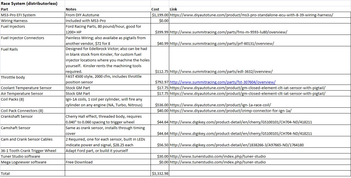
Some notes on this system: the crank and cam sensors are magnetic sensors; they work by looking for a steel or iron tooth on a gear wheel, or some other protruding steel or iron feature. The crank sensor requires a 36-1 wheel on the crank. This is a steel wheel with 36 teeth, one for each 10 degrees, except that one tooth is missing (hence 36-1). Lots of Ford vehicles have come with them so they are plentiful in the junkyards and on ebay, but they would have to be adapted to the FE. I ended up machining my own version. The cam sensor can be put through the timing cover of the FE, and a bolt can be screwed into the top gear at the right spot, so that the cam sensor detects the bolt head as it goes by. The cam sensor tells the EFI system that the next time a TDC of #1 occurs, it is on the firing stroke. This is required for full sequential fuel injection. The MS3-Pro drives the coils directly, based on the inputs from the cam and crank sensors.
More info later...


