Author Topic: The Road to Drag Week 2014 - May 11  (Read 22144 times)

0 Members and 1 Guest are viewing this topic.

jayb

  • Administrator
  • Hero Member
  • *****
  • Posts: 7406
    • View Profile
    • FE Power
The Road to Drag Week 2014 - May 11
« on: May 11, 2014, 03:02:33 PM »
I've had a very productive weekend on this project, thanks in part to the fact that my wife took the kids and went down to visit some relatives in Iowa, so I was left by myself starting early Saturday morning.  Its amazing what you can get accomplished without any interruptions.  The CNC machines have been running in the background all weekend making FE intake adapters, and haven't required much attention, so I was free to focus on getting the SOHC together.

Last week I had been trying decide between cutting the spring pockets on the heads larger to make room for larger diameter springs, or buying new springs that would fit the existing spring pockets.  After my post last weekend I was looking at the heads in more detail and realized that in addition to cutting the spring pockets I would need to clearance some of the cam towers to make them fit; even with 1.55" diameter springs they had been too close and had required some clearancing.  I didn't really want to cut those any more than I already had, and when my machine shop guy said he was pretty busy this week, I bit the bullet and bought new springs, retainers, and spring locators.  They arrived on Wednesday this week, after I ordered them Monday morning; Comp Cams is really fast for shipments in most cases.  First thing I did was check the spring locators, and sure enough, they were just a hair too large to fit down in the spring pockets.  The springs themselves fit into the pockets nice and snug, thankfully.  Thursday and Friday nights were busy, but late Friday night I finally got out to the shop and started working on the spring locators.  I ended up chucking each one into my lathe and cutting it down in diameter by .025", and then they fit nicely inside the spring pockets.  Here's a picture of two of the locators; the one with the shiny edge has been turned down:


On Saturday morning I got an early start after seeing off the wife and kids, and started to get the heads re-assembled.  I try to be really careful while doing this, making sure to check everything like any good engine assembly shop would.  The springs all checked about the same at 245 pounds on the seat and 625 pounds open, and still had about .100" to go before coil bind.  I would have liked to run closer to coil bind if possible, but then the seat pressure would be getting too high; it is rather high as it is for this engine.  I also made sure to check the retainer to valve seal clearance; here's a photo of this check:
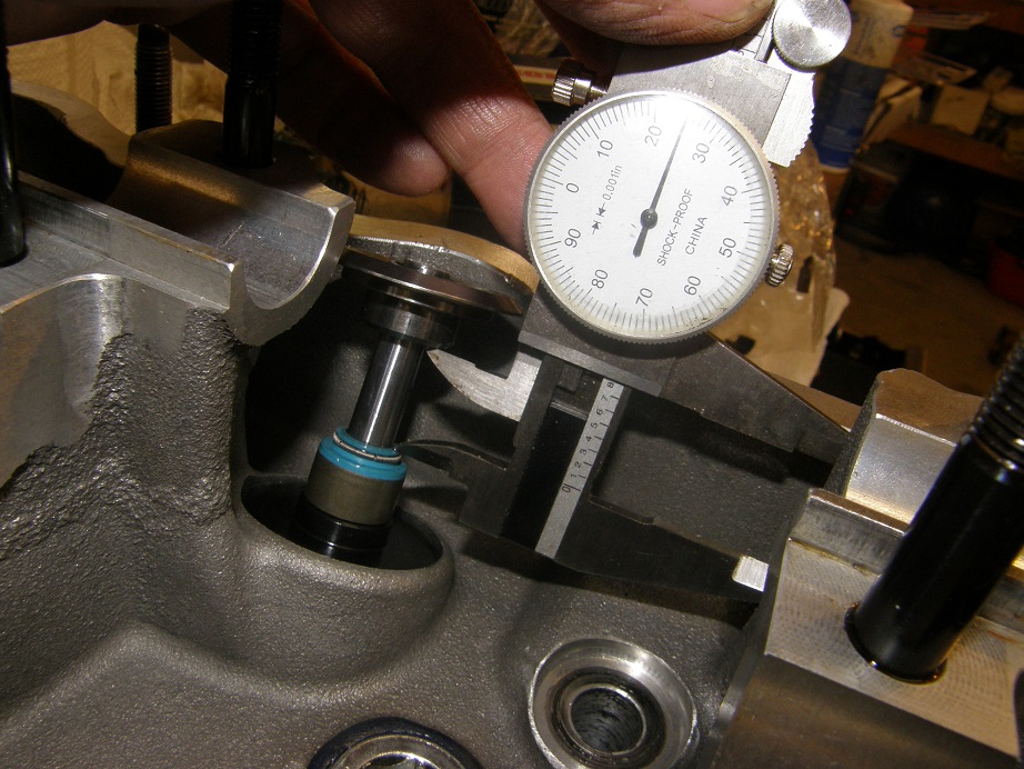


Net lift on my cams is 0.720", so I should have a little over .100" clearance to the seal.  I also assembled the heads with Manley +.050" valve locks to get the necessary installed height.  On the exhaust side I only need .030" shims under the spring locators, so using a standard valve lock would have prevented me from hitting the desired installed height, even if no shims were present.  The other option this presents is the ability to go to standard valve locks in the future if I want to increase the spring pressure.  I think I will let the dyno tell me if that is a requirement or not.

I worked on the heads all day, checking and re-checking various items, and finally by dinner time on Saturday I had the heads finished up and ready to install.  Here's a photo:
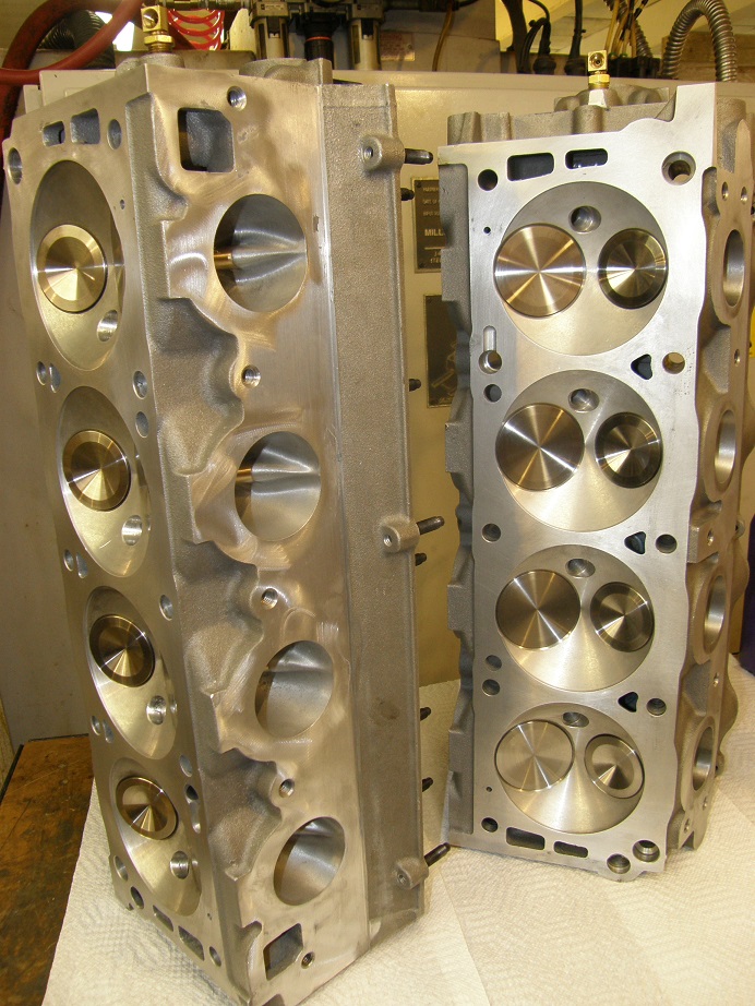


They look pretty good with those new Manley valves in there, and the flow numbers will be back up to normal now that the Ferrea valves are no longer in the heads.

After dinner I decided to install one of the heads on the short block.  This is always an issue with this particular engine, because I have to use copper head gaskets on it.  The reason is that this block has a custom bore spacing; stock FE bore spacing is 4.63", but this block has been offset bored to 4.70".  This allows me to run a larger bore than would normally be possible, but it also means that stock head gaskets won't work, so custom copper head gaskets are required.  And, of course, copper head gaskets tend to leak on street engines.

Of course, the head gaskets are only one potential source of leaks with this engine; it is prone to leaks in a variety of areas, and in fact leaks in this engine took me out of the competition at Drag Week in 2011.  One reason is that when the block was offset bored, and bored for a larger diameter sleeve, on three of the cylinders we broke through the aluminum casting and into the water jacket.  This means that three of the cylinder sleeves are actually wet, with water on the other side of the sleeve.  On my first go-around with the engine in 2009, after installing the sleeves I used a chemical sealant to seal up the block.  This involved filling the entire block with this stuff, then pressurizing it to 20 psi for a few minutes to force the sealer into any gaps, then draining it all back out, and finally cooking the block at 200 degrees for several hours to cure the sealer.  This procedure worked, and the engine ran without problem from 2009 until 2011, when apparently the sealer gave up and the block started leaking water down past the sleeves and into the crankcase during Drag Week 2011.  After that debacle I took the engine completely apart and installed new sleeves; these sleeves have been cut with a groove on the back side of the sleeve and have an O-ring fitted.  So now all 8 cylinders have new sleeves with an O-ring seal at the bottom, which should solve the problem.  However, when I disassembled the engine I also found leaks up at the tops of the sleeves, where water was coming up between the sleeve and the casting at the deck.  This is a more difficult problem to fix; I didn't want to groove the top of the sleeves for a second O-ring because the top is where most of the compression pressure is.  This is where the difficulties with the head gasket come in.  The copper head gaskets I buy come with a special silicone sealer for use around the water jacket openings in the block and the head, but on this engine I'm also using it to try to seal around the tops of the cylinder sleeves.  This isn't an easy area to seal because it is right next to the O-rings that are cut into the tops of the sleeves, so the gasket isn't going to lay perfectly flat in this area.  After giving this some thought I decided to do the best I could with the silicone, and once I got the engine on the dyno I would run it with a radiator at first, rather than the dyno's cooling system, and use some Moroso ceramic sealer in the cooling system to seal up any leaks that may be there.  I'm also concerned about the heads on this engine; they leaked at first too, but have been sealed up with welding.  However, I don't know how much I can trust the welding after several heat cycles, so using the ceramic sealer may prevent problems there as well.

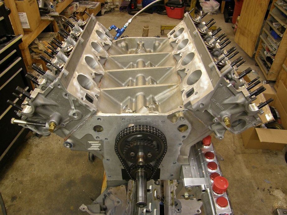
Trying to be as careful as I could, and working quickly so as to get the head on before the sealer set up, I got the right side head installed and torqued into place.  This morning I got back out to the shop by 8:00 and did the other head.  Here's a photo of the engine with both heads installed:


Next up on the assembly list is the backing plate for the timing cover.  This is the plate on the SOHC that seals to both heads, the water jacket openings in the block, and the normal FE timing cover position.  There are 23 bolts that go through this backing plate, and it has to be installed before the timing chain and gears can be installed, and the front cover put into place.  I've tried to do this in a single operation before, and it always seems like some of the sealer is dry before I finally get the front cover installed and bolted down, so I end up with leaks.  As a results I've started to do this assembly in two stages.  First, I get the backing plate installed with sealer, and tightened down with some dummy bolts, until the sealer is dry.  Then, with the backing plate stuck firmly to the block and heads, I can take my time assembling the gears and chain, and then have plenty of time to install the timing cover.

Here's a picture of the top of my assembly bench with the first five gaskets required for the backing plate installation.  I also have a bunch of dummy bolts laid out to hold the backing plate in position, plus the fuel pump gear and pedestal and the tensioner arm, which are also required:


Two of the gaskets above are SOHC specific, but the gasket around the primary timing chain and the water pump gaskets are standard FE parts.  I applied sealer to all the required surfaces and then stuck the gaskets to the block and heads.  In the picture below there are also two small blue gaskets that I cut from an old fuel pump gasket; these don't really seal anything but are used to space the backing plate out fromthe block and heads the same amount as the other gaskets, to avoid putting a twist in the backing plate:
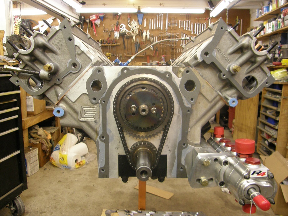


Next I put more sealer on the exposed gaskets to seal to the backing plate, and then installed the plate, working quickly to get all 23 bolts installed.  For most of the spots, rather than using a short bolt, I use a long bolt with a nut on it, and a couple of washers between the nut and the backing plate.  I just tighten the bolts in a few turns and then tighten the nuts to clamp the backing plate to the block and heads.  Here's a picture of the engine with the backing plate installed, and all the temporary fasteners in position:
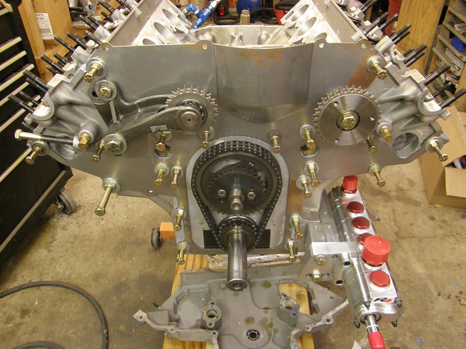


I'm going to let this dry for a couple of days, and then start the fun stuff, which is installing the cams, assembling the chain drive, and installing the front cover.  Prior to the front cover installation I need to drill a hole in it for a cam sensor, because I'm going full sequential EFI on this engine.  Once the front cover is installed I can tighten up the chain and check piston to valve clearance, and then install the last two valvesprings in place of the checker springs on cylinder 1.  With luck I will get all that done next weekend, and then be ready for installing the oil pan, the intake manifold, and the front end parts of the engine...


Jay Brown
- 1969 Mach 1, Drag Week 2005 Winner NA/BB, 511" FE (10.60s @ 129); Drag Week 2007 Runner-Up PA/BB, 490" Supercharged FE (9.35 @ 151)
- 1964 Ford Galaxie, Drag Week 2009 Winner Modified NA (9.50s @ 143), 585" SOHC
- 1969 Shelby Clone, Drag Week 2015 Winner Modified NA (Average 8.98 @ 149), 585" SOHC


cammerfe

  • Hero Member
  • *****
  • Posts: 1659
    • View Profile
Re: The Road to Drag Week 2014 - May 11
« Reply #1 on: May 11, 2014, 04:45:40 PM »
Jay, you could easily turn your posted information into an SOHC manual. I, for one, would be right at the front of the line waiting for them to come off the presses. Or you could do them as an ebook and/or offer it on a disk.

KS

jayb

  • Administrator
  • Hero Member
  • *****
  • Posts: 7406
    • View Profile
    • FE Power
Re: The Road to Drag Week 2014 - May 11
« Reply #2 on: May 11, 2014, 04:52:25 PM »
You know Ken I keep threatening to write an SOHC book, but I just haven't had time to get to it.  At some point I will...
Jay Brown
- 1969 Mach 1, Drag Week 2005 Winner NA/BB, 511" FE (10.60s @ 129); Drag Week 2007 Runner-Up PA/BB, 490" Supercharged FE (9.35 @ 151)
- 1964 Ford Galaxie, Drag Week 2009 Winner Modified NA (9.50s @ 143), 585" SOHC
- 1969 Shelby Clone, Drag Week 2015 Winner Modified NA (Average 8.98 @ 149), 585" SOHC


Qikbbstang

  • Hero Member
  • *****
  • Posts: 892
    • View Profile
Re: The Road to Drag Week 2014 - May 11
« Reply #3 on: May 11, 2014, 10:48:10 PM »
The potential leaking issues have got to play havoc with your piece of mind.  Your mentioning the "Chemical Sealant'" rung a bell for me with a customer I had back during the height of the Cold War that had a contract to seal thousands of the cylindrical castings and covers that were part of underwater listening devices to keep track of Rusky subs. Get this, they filled large heavy duty pressure vessels with the parts and submerged them with sealing fluid, finally they then pulled a vacuum on the vessels to force the submerged parts to draw in the sealant into their pores when the vacuum was released.  I also saw a BBC head that had its sealant fail and it was ugly - potato chips in sheet form all over inside the heads water jackets. I think an Achilles heel to the chemical sealant is overheating, with the treated parts sealed with a plastomeric that's cured at only 200F I'd bet that sealant is not going to fare well in a  steaming hot motor.
   Since all the metals/components all expand differently with heat and of course Murphy's Law #5 = all the different rates of metal expansions will not make for better sealing.  I like your idea of the ceramic sealing w/radiator on dyno. You might think about synthesizing an operating temperature range you feel the motor will run within, seal it there and try to keep in that temp range when "running" it.  How anything seals by plugging leaks with particles seems like Mission Impossible to me, I'd think you'd have to build up enough pressure to force a large enough stream with enough particles to get caught and eventually build up enough to dam the leaking passages.   
« Last Edit: May 11, 2014, 10:54:37 PM by Qikbbstang »

machoneman

  • Hero Member
  • *****
  • Posts: 3853
    • View Profile
Re: The Road to Drag Week 2014 - May 11
« Reply #4 on: May 12, 2014, 07:23:56 AM »
I have a question Jay that you may have answered long ago but I may have missed it. It's about the valve-to-piston clash and the root cause. You were looking into a host of possible causes (pin flex, pin bending, piston deflecton, etc.) but weren't sure of the true cause. If the answer is in another set of posts, perhaps you could direct me to it.

I agree that a SOHC book, when you have time, is a wonderful idea :)
Bob Maag

jayb

  • Administrator
  • Hero Member
  • *****
  • Posts: 7406
    • View Profile
    • FE Power
Re: The Road to Drag Week 2014 - May 11
« Reply #5 on: May 12, 2014, 07:36:08 AM »
Bob, I have never figured out that problem.  It is still a mystery to me.  For what it's worth, I kept that problem in mind when I specified the pistons for the engine I'm assembling now, and there is quite a bit more radial clearance around the valve with these pistons.  So, if the same problem occurs, regardless of the unknown cause, the piston design on this engine should prevent any contact with the valve.
Jay Brown
- 1969 Mach 1, Drag Week 2005 Winner NA/BB, 511" FE (10.60s @ 129); Drag Week 2007 Runner-Up PA/BB, 490" Supercharged FE (9.35 @ 151)
- 1964 Ford Galaxie, Drag Week 2009 Winner Modified NA (9.50s @ 143), 585" SOHC
- 1969 Shelby Clone, Drag Week 2015 Winner Modified NA (Average 8.98 @ 149), 585" SOHC


machoneman

  • Hero Member
  • *****
  • Posts: 3853
    • View Profile
Re: The Road to Drag Week 2014 - May 11
« Reply #6 on: May 12, 2014, 07:42:13 AM »
Thanks Jay! Good idea on increasing that radial clearance. I'll bet you also have one of those inexpensive borescopes (sp?) to look into the bores after some running time.   
Bob Maag

jayb

  • Administrator
  • Hero Member
  • *****
  • Posts: 7406
    • View Profile
    • FE Power
Re: The Road to Drag Week 2014 - May 11
« Reply #7 on: May 12, 2014, 08:00:15 AM »
I do have one of those, the operative word being "inexpensive" LOL!  Pretty hard to see anything with it, but after the dyno sessions it will certainly be worth a look.
Jay Brown
- 1969 Mach 1, Drag Week 2005 Winner NA/BB, 511" FE (10.60s @ 129); Drag Week 2007 Runner-Up PA/BB, 490" Supercharged FE (9.35 @ 151)
- 1964 Ford Galaxie, Drag Week 2009 Winner Modified NA (9.50s @ 143), 585" SOHC
- 1969 Shelby Clone, Drag Week 2015 Winner Modified NA (Average 8.98 @ 149), 585" SOHC


cobracammer

  • Hero Member
  • *****
  • Posts: 1165
    • View Profile
Re: The Road to Drag Week 2014 - May 11
« Reply #8 on: May 12, 2014, 10:34:03 AM »
Hey Jay....  2 quick questions.  1st, are all the bolts the same thread size on this engine?  (i.e the dummy bolts for sealing the gaskets?)

and second question is the checker springs on the heads.  Would you mind breaking down how you set the timing with the checker spring? (I wasn't sure if this was a step you did specifically because of the Cams you used?  Wanted to see if I also needed to purchase checker springs for my build)

Thanks
Jason
2005 Saleen S281 (427 SOHC 2 X 4 EFI swap), T56 Magnum XL 6 speed, 9" Currie rear with 3.89 Gears

jayb

  • Administrator
  • Hero Member
  • *****
  • Posts: 7406
    • View Profile
    • FE Power
Re: The Road to Drag Week 2014 - May 11
« Reply #9 on: May 12, 2014, 02:14:22 PM »
The bolts in the front cover are a variety of sizes.  Most are 3/8" or 5/16", but there are a couple of 7/16" and a couple of 1/2" also, if you include the bolts for the chain tensioner and the fuel pump gear stand.

I will go over setting the timing in detail in a later installment on this board, either next weekend or the weekend after.
Jay Brown
- 1969 Mach 1, Drag Week 2005 Winner NA/BB, 511" FE (10.60s @ 129); Drag Week 2007 Runner-Up PA/BB, 490" Supercharged FE (9.35 @ 151)
- 1964 Ford Galaxie, Drag Week 2009 Winner Modified NA (9.50s @ 143), 585" SOHC
- 1969 Shelby Clone, Drag Week 2015 Winner Modified NA (Average 8.98 @ 149), 585" SOHC


cobracammer

  • Hero Member
  • *****
  • Posts: 1165
    • View Profile
Re: The Road to Drag Week 2014 - May 11
« Reply #10 on: May 12, 2014, 02:27:42 PM »
Thanks Jay... And I agree with Cammerfe... I would definitely buy your SOHC book!  lol
Jason
2005 Saleen S281 (427 SOHC 2 X 4 EFI swap), T56 Magnum XL 6 speed, 9" Currie rear with 3.89 Gears

cjshaker

  • Hero Member
  • *****
  • Posts: 4460
    • View Profile
Re: The Road to Drag Week 2014 - May 11
« Reply #11 on: May 13, 2014, 08:37:02 PM »
I have no experience in SOHC motors, but after watching some ultra slow speed valve videos (filmed at very high rpms) I'm amazed at the movement of the entire valve and spring system in heads at speed. They dance around pretty good and it's amazing they stay together at all. The heads of the valves would move around at full lift and bounce off the seats pretty badly (and multiple times). I assume the valve heads swaying around was due to stem flexing. Spring harmonics can really play havoc with these issues as well.

Knowing that you have pretty tight clearances with your cams lift and piston domes, it wouldn't surprise me if that is where the witness marks came from.
Doug Smith


'69 R-code Mach 1, 427 MR, 2x4, Jerico, 4.30 Locker
'70 F-350 390
'55 Ford Customline 2dr
'37 Ford Coupe

jayb

  • Administrator
  • Hero Member
  • *****
  • Posts: 7406
    • View Profile
    • FE Power
Re: The Road to Drag Week 2014 - May 11
« Reply #12 on: May 13, 2014, 09:23:10 PM »
Doug, can you point me towards the videos you mention?  I'd be very interested in seeing those.  If the valve heads were moving around a little at speed that would explain the PV contact I saw in my previous incarnation of this engine.
Jay Brown
- 1969 Mach 1, Drag Week 2005 Winner NA/BB, 511" FE (10.60s @ 129); Drag Week 2007 Runner-Up PA/BB, 490" Supercharged FE (9.35 @ 151)
- 1964 Ford Galaxie, Drag Week 2009 Winner Modified NA (9.50s @ 143), 585" SOHC
- 1969 Shelby Clone, Drag Week 2015 Winner Modified NA (Average 8.98 @ 149), 585" SOHC


Dave427SOHC

  • Jr. Member
  • **
  • Posts: 35
    • View Profile
Re: The Road to Drag Week 2014 - May 11
« Reply #13 on: May 13, 2014, 09:55:33 PM »
I seen a couple on youtube  heres one Jay  https://www.youtube.com/watch?v=yVwzXeAtEHg

Qikbbstang

  • Hero Member
  • *****
  • Posts: 892
    • View Profile
Re: The Road to Drag Week 2014 - May 11
« Reply #14 on: May 13, 2014, 11:01:15 PM »
Those captured oscillations wreck havoc on my brain thinking how there could be oscillations upon oscillations and how strobe rates could show different  variations.  I guess those are all captured by strobes?