I apologize in advance for this extremely long post, but there is a lot of information I wanted to share here.
It has really taken a long time to get all the intake manifold development and testing finished for my cylinder head project, much longer than originally anticipated. It all started back in 2020, so it has been over a year and half to get everything finished up. The scope of the work has changed along the way, to include a complete revamp of the rocker arm system (from aluminum to steel), and the original plan for building three intake manifold options for the cylinder head package has morphed into at least five, and probably six, intake manifolds that will be offered. Nevertheless, at this point I'm pretty happy with where everything stands, and will be going to production tooling on the intakes very soon.
A quick word about the dyno mule. This engine has been a real trooper. It has been through tremendous abuse, starting with all the broken aluminum rocker arms and related bent pushrods that showed up in the original test program, followed by a refit using the steel rockers, plus an update to the steel rockers to move from 3/8" adjusters to 7/16", and make a couple of other minor tweaks. It has endured one major and two minor plastic manifold explosions that ruined the plastic manifolds and in one case blew shards of plastic shrapnel all over the dyno room and into the cylinders of engine itself. It has seen uncounted hours of running, and a total of 254 dyno pulls, many of them to 7500 RPM. And it is tired; the right bank looks pretty good with all the cylinders showing 170 to 180 psi of compression, but #5 is down to 140, and #6 is down to 80 psi. Even so, the engine is still making 885-890 horsepower with the original 8V intake manifold. It has been a kickass engine.
After multiple redesigns and lots of testing, I've tentatively settled on building two 4V intake manifolds, two 8V intake manifolds, a tunnel ram and the IR crossram intake. I've put pictures and dyno data for each one below, so that they can be compared. All the data shown is with the dyno mule fitted with the RE version of the cylinder heads, and 2-1/8" dyno headers. Based on some back to back testing, the SE version of the heads will be down about 15-20 horsepower from the RE version.
4V Intakes:
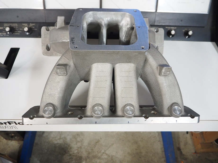
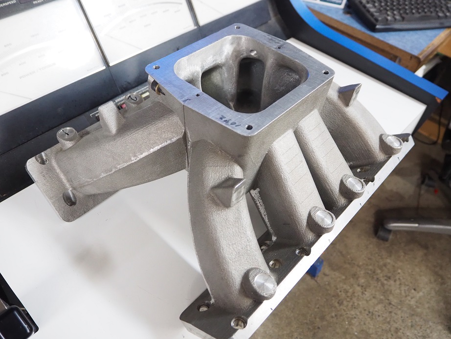
The picture below shows the original 4V intake, that was cast at a local foundry. My dyno junky friend Royce nicknamed this one "Rasputin", because it was tall and terrible! This one ran originally on the engine with the aluminum rocker arms, and after discontinuing testing to update the rocker arm system it was sent down to Joe Craine for a little porting tune up. After getting it back it was tested again with the new steel rocker system, and made a little more power than it had originally, so the revised design will be incorporating the changes Joe made. Also, this intake was originally designed to split in half for easy porting, but Joe didn't think that was necessary due to the easy access to the runners, so for production this one will be a single piece design:
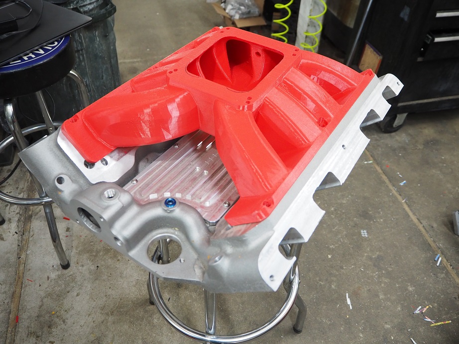
After testing the previous intake I had a couple customers contact me, wondering about hood clearance. This intake of course was not going to fit under anyone's hood, not even with a CJ or Boss 9 scoop. So I decided to take a stab at another 4V intake design, with an eye towards making it fit a car with a Mustang shaker scoop. Because of this the carb mounting point and slant of the carb pad was positioned in the same place as a factory 428CJ intake. Due to the height of the head ports, this intake was going to be 2" higher than the factory intake no matter what. However, if a low profile EFI throttle body was used, based on the height calculations the shaker scoop would still fit.
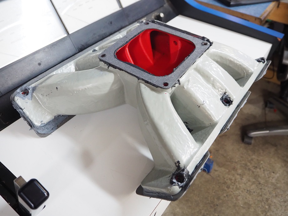
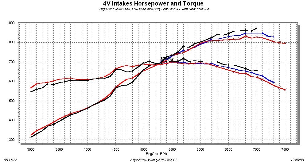
The 3D printed manifold pictured below is the second version that I designed (Note in the second picture that the manifold plastic has been painted; more on this later). The first one did poorly on the dyno, making only about 770 HP on the dyno engine. After revising the runner design, the one pictured made 825 HP, and with a 1" spacer it went all the way to 848 HP at 7100 RPM, which was down only a small amount from the tall 4V intake. I think this manifold would be a really good compromise for someone looking to maintain the stock hoodline of their car.
The graph below shows horsepower and torque from tall 4V, the short 4V with no spacer, and the short 4V with a 1" spacer (3000 to 5000 RPM with the spacer is nearly identical to without, and is not shown in the graph). All the dyno graphs shown in this post have been standardized with a torque and horsepower range of 300 to 900, in order to make comparisons easier.
 8V Intakes:
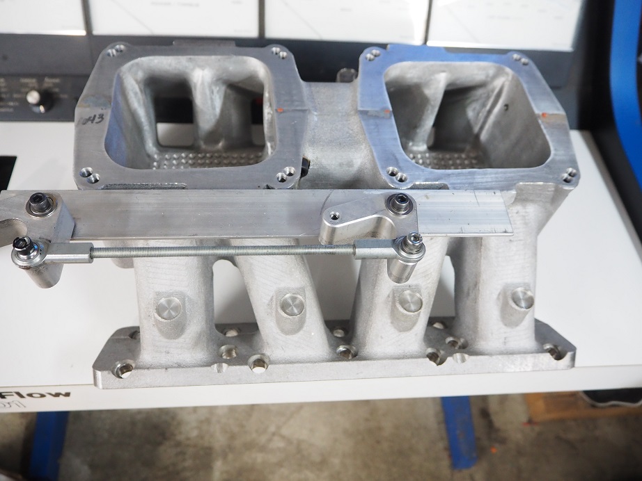
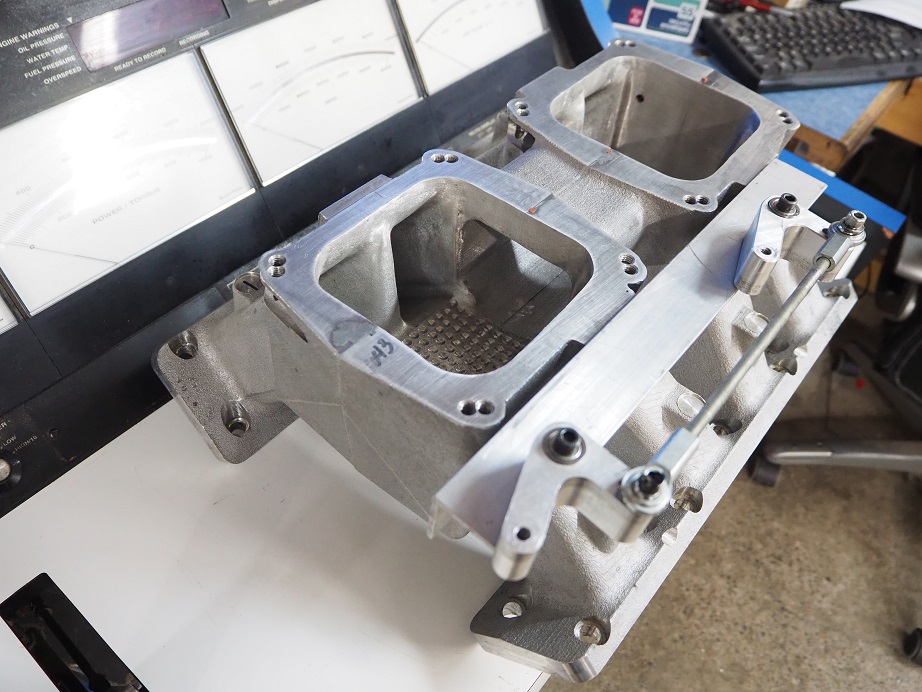
Similar to the original 4V intake, I designed the original 8V intake and had it cast at my local foundry, then had Joe Craine tweak it for me before I ran it with the revised steel rocker arm system. To date, this manifold has performed better in horsepower production than any other manifold I've tried, and that includes two sheet metal style intakes and two tunnel wedge style intakes. It is not clear to me why this manifold works so well, because from a pure design standpoint it is a compromise. One thing I've learned over the years of testing though is that the engine wants what it wants, and sometimes it is not predictable. Like the tall 4V intake, Joe's changes will be incorporated into the production version. Also like the tall 4V, this manifold was originally designed as a two piece intake, but will be a single piece in production. Pictures of this intake are shown below:
In order to make peak power I really wanted to try a sheet metal style intake on this engine. Long ago when I bought my 3D printer, I had envisioned printing plastic intake manifolds and testing them on an engine, and I did this quite a bit during this intake development. Of course, there was a learning curve. The manifolds come off the 3D printer looking beautiful, perfectly formed runners, nice radiuses where they were designed in, etc. They look and feel solid, but actually the outer layers are only about .060" thick, and the interior portions are a honeycomb-like structure. One thing I learned the hard way is that despite their appearance, they are not airtight. Below is a picture of the first sheet metal style intake I printed and tested on the dyno. Royce nicknamed this one the Red Devil:
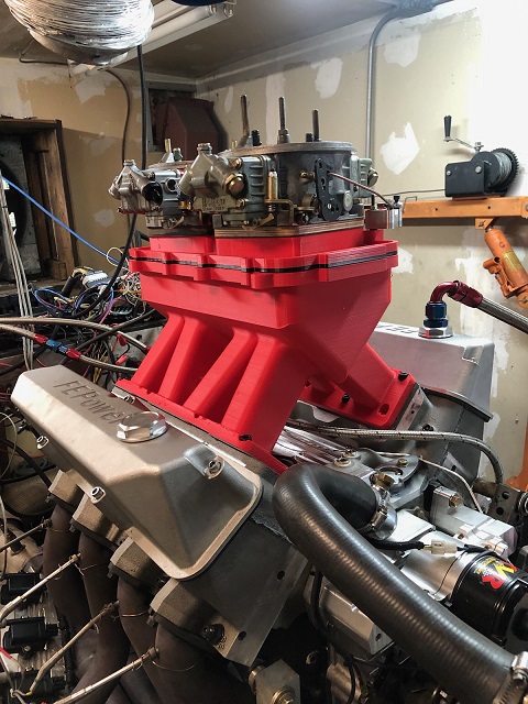
The name turned out to be oddly clairvoyant. When the engine was started with this manifold installed, it didn't seem like it was running right. Little did I know that there was a massive vacuum leak, right through the plastic of the manifold. When the throttle was advanced, the engine backfired and blew the manifold to smithereens! Picture of the aftermath is below:
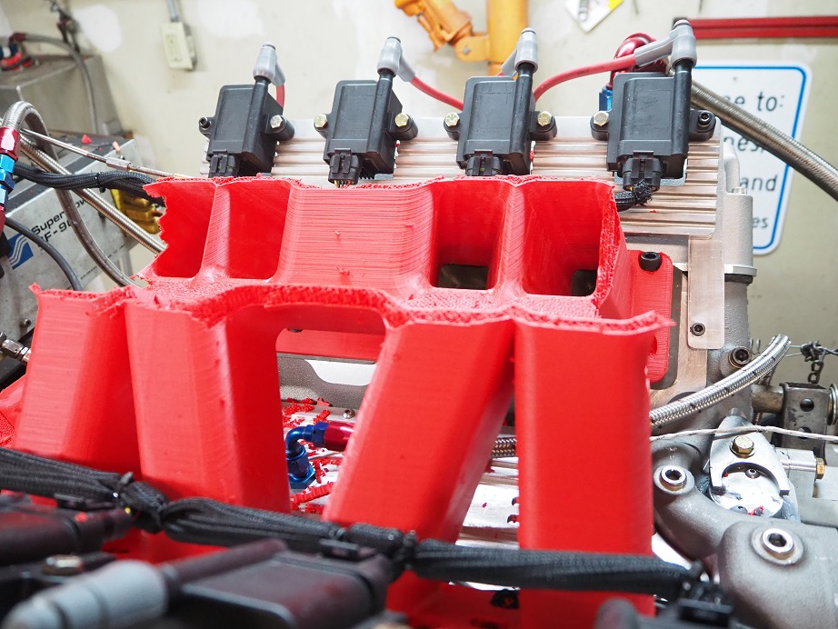
The explosion caused a loud bang and a blinding flash, and blew both the Dominator carbs over the left valve cover, hanging by the fuel lines and on fire. We got the fire out quickly so no damage. Within 20 seconds we were all laughing our butts off over this deal; holy crap, the explosion and resulting fireball was SPECTACULAR! If there had been a camera running in the dyno room when that manifold exploded, the video would have a million hits on youtube by now.
Anyway, this stopped testing for a bit while the engine was pulled apart looking for problems. We found shards of plastic in all the cylinders, some of them stuck down between the piston and the top ring, but no other damage. Put the engine back together with the aluminum 8V intake, and it made the same power as before, so no problems there. From that point forward, after 3D printing a plastic intake, it was painted it with two coats of garage floor epoxy paint, to make sure that it was sealed before installing it and testing it on the dyno.
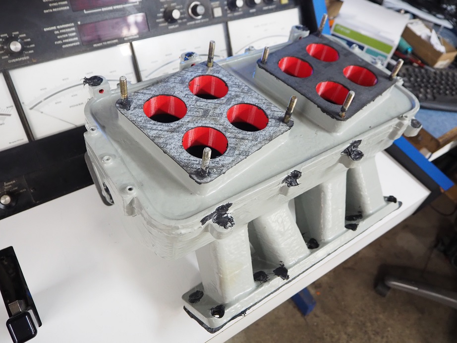
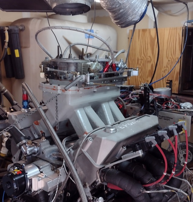
Two more sheet metal style intakes were designed, and were tested on the engine. One had fairly short runners and a fairly large taper in the runners (first picture below), and the other had longer runners and less taper (second picture). Neither one of them made close to the power of the 8V intake that had been originally designed. The first one was tested several months ago, and the testing went fine with no issues (I am now extremely cautious when starting the engine with a plastic intake). The second one was the last intake tested, just on Tuesday this week, and after three dyno pulls it was clear it wasn't going to get close to the 890 HP the original 8V was making; it was only getting to 860 HP at 7000 RPM. That one looked like it might go a little higher than 860 HP if we ran the engine to 7500 RPM, but inexplicably when starting the engine the last time for that pull to 7500 we had a minor backfire and that broke the sides out of the intake. The plenum portion of the tunnel ram intake also broke due to a minor backfire when it was tested the first time; the conclusion is that the bigger the plenum, the bigger the volume of air/fuel mixture ready to ignite, and the shorter the lifespan of the plastic intake!
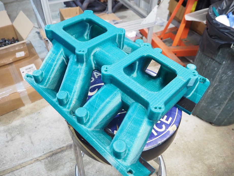
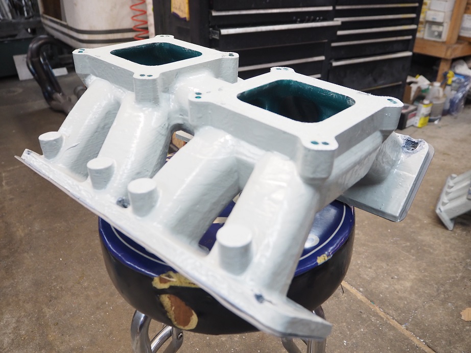
One other intake that I really wanted to do was an 8V intake that looked kind of like a factory tunnel wedge manifold. Three 3D printed versions of this one were completed. The first one gave disappointing results, only about 825 HP on the dyno engine. So back to the drawing board where the runner shapes were redesigned, and also raised a little bit. After 3D printing that one a mistake was found in the design of how the runners blend into the plenum; sometimes it's hard to see all the potential issues with a design by looking at it on the computer. Back in one more time to fix up the blending issues, and then that manifold was printed, painted and tested. The extra effort was rewarded with 875 HP from that one, and still climbing at 7000 RPM. Pictures of the final tunnel wedge version, in raw plastic and painted, are below:
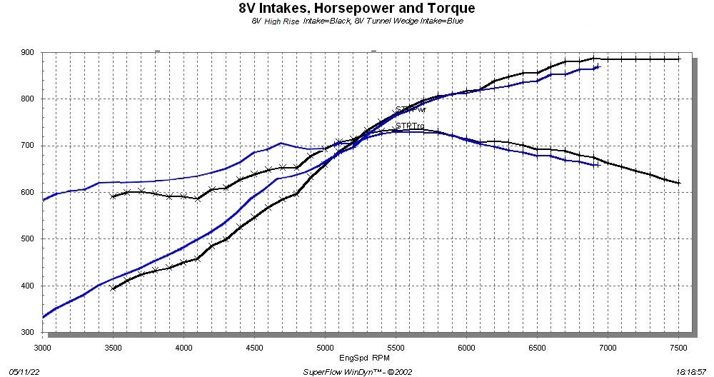
Dyno data for the 8V High Rise and 8V Tunnel Wedge manifolds is given below. The 8V high rise makes more top end power than any of the other intakes, and holds in the 885 to 890 HP range from 6800 all the way to 7500, which to me is quite impressive. There were a couple of pulls with the 8V high rise that netted 894 HP, but the data was a little questionable because the peaks were at one engine speed only, so those pulls weren't included in this data. We thought with a little tweaking we could get this manifold to 900 HP, but nothing we did seemed to help. I went so far as to wrap the headers, but got no change in power. Then I built a whole new set of headers, with 2-1/4" primaries, and actually lost 5 HP on the top end. I tried different jetting, different valve lash settings, etc., with no change. I stopped short of actually running the engine at a really cold temperature, and icing down the intake, because I figured that would be cheating

So despite my best efforts I didn't get this engine to 900 HP. I did not try a higher ratio rocker, which may have gotten it there. There is also have another cam to try, specified by Chris Padgitt at Bullet Cams, but that one hasn't been installed yet. This engine needs to be freshened up, before we get back to flogging it with a new cam and springs, higher ratio rockers, and ported versions of the heads; as mentioned before, the heads on this engine are unported.
The 8V tunnel wedge manifold makes better power than the 8V high rise at the lower engine speeds, and appears to still be climbing at 7000 RPM and 875 HP. Hindsight being 20/20 this one should have probably been run to 7500 RPM too, but the results were satisfactory up to 7000 so it was left at that. I was putting my bets on the tunnel ram...
 Tunnel Ram and IR Crossram Intakes:
These two manifolds are torque monsters, beating the best of the 4V and 8V manifolds by a good 30 foot pounds of torque, which is an amazing 1.5 lb-ft per cubic inch. I have never had a naturally aspirated engine that makes that kind of torque per cube on my dyno before. The Individual Runner Crossram manifold had been planned since the very early days of starting the cylinder head project, but for some reason it never dawned on me to build a traditional tunnel ram. I don't know why; a very large percentage of the people who purchase my intake adapters for their FEs use a Weiand tunnel ram on them. Seems like FEs and tunnel rams go together.
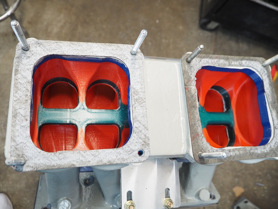
Anyway, I finally wised up and designed a tunnel ram intake for the cylinder heads. Pictures of the intake are below. I took a lot of the design cues from the Weiand 351C tunnel ram, which works extremely well. It was 3D printed, then displayed at the FE Power booth at PRI this year. In March Royce the Dyno Junky drove up, and we tried to test it, along with a couple of other intakes. As mentioned previously though, a minor backfire cracked the plenum part of the intake, so no testing was possible. A couple weeks later I had reprinted the plenum area and bolted it back on to the base. This time the testing went perfectly, and I was blown away by the 763 foot pounds of torque that the tunnel ram made. But like a lot of tunnel rams, it didn't pull all the way to 7000 RPM. It peaked in the 6300-6500 RPM range, at about 865 HP, and then fell off.
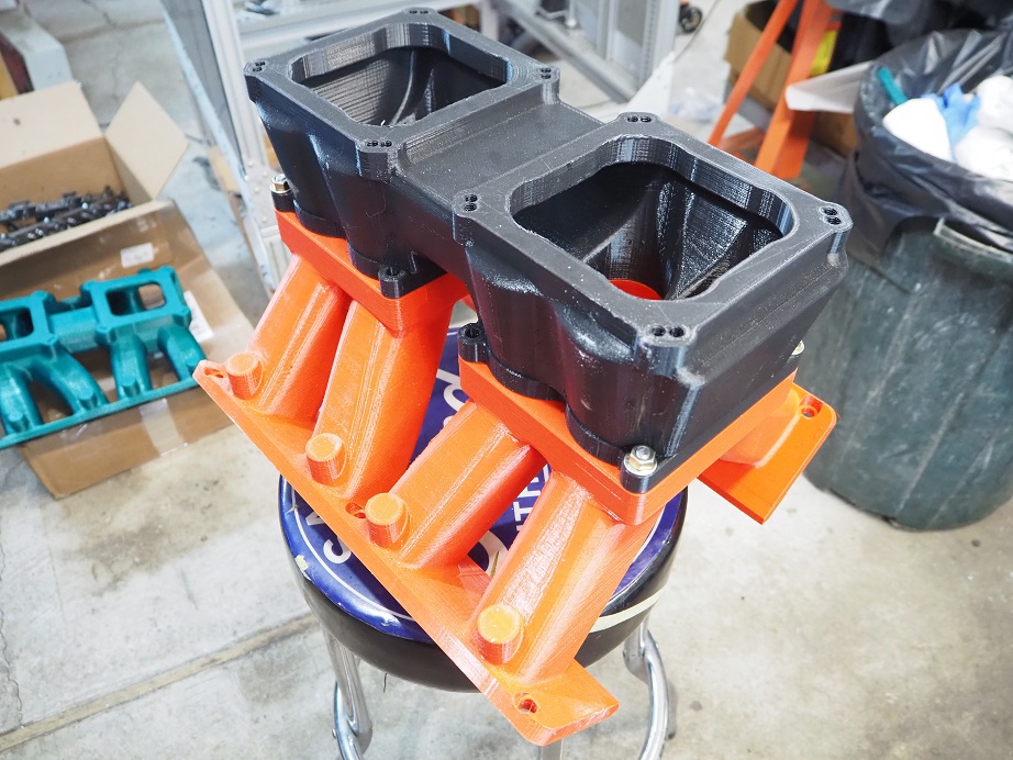
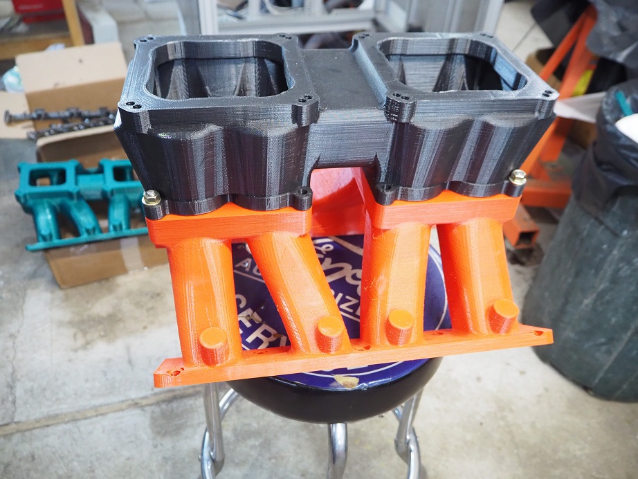
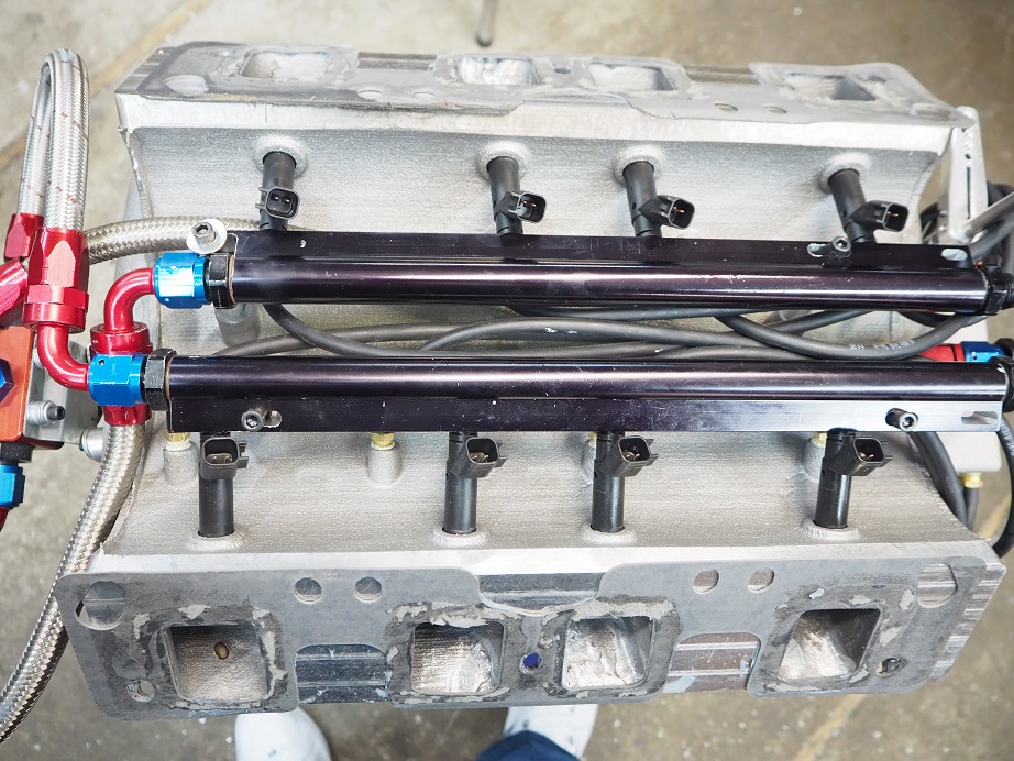
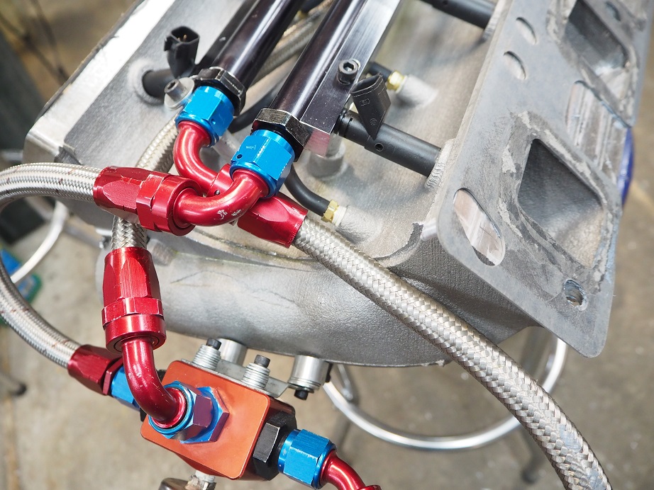
The IR crossram intake was the most complex intake to get up and running on the dyno. This one was cast originally as eight individual runner castings, to bolt onto the intake adapter. However, this arrangement made it nearly impossible to get the fuel injectors, fuel rails, and vacuum taps (which are all under the intake) installed with it assembled on the intake adapter. After fighting with that for several days I finally concluded that I needed to redesign the intake as a single piece, which would be flipped over for installation of the fuel and vacuum system, and then installed on the intake adapter.
After redesigning the casting and getting it cast, of course I had to completely rewrite the CNC code to machine the intake. I also needed a new machining fixture. After getting all that done, the fuel system and vaccuum system was test assembled under the intake. The new casting had some bosses on the bottom side of the intake to mount the fuel rails, but one of them turned out to not be in the ideal spot, so that will have to be changed before production tooling is made. But overall the new setup worked. The photos below shows how the underside of the intake looks with the fuel and vacuum systems installed:
Next the throttle linkage had to be redesigned to work with the new casting. The first version did not look robust when it was completed, and it was too high off the top of the intake, so a second version was started from scratch. This one still has some issues, and it will be tweaked a little before finalizing it for production, but it works well enough to run on the dyno. The production casting will be changed to add some bosses for attaching a return spring on each bank of the intake, plus an idle screw and an opening stop screw for each bank. Finally, when it came time to mount the fuel pressure regulator I wanted it up front for easy access, and had neglected to add a boss at the front of the casting for mounting it, so it was just screwed into the front runner. The production casting will put a boss in that position with a couple of mounting holes, to make it easier and cleaner to mount.
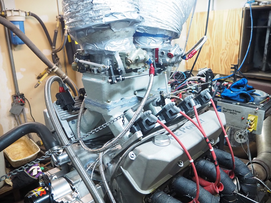
All this took a lot of time to accomplish; the intake probably came apart and went back together six or eight times before it was ready for the dyno. But finally this week the time arrived. Here are some pictures of this intake mounted on the engine:
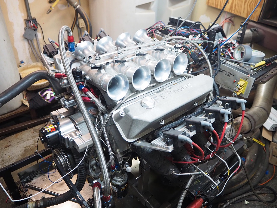
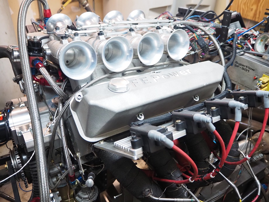
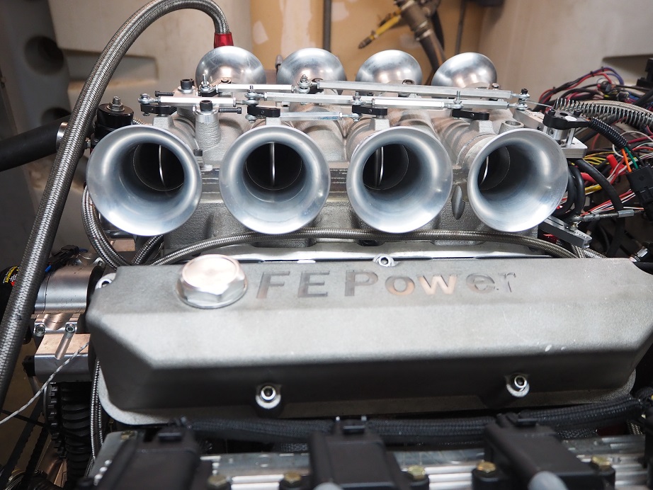
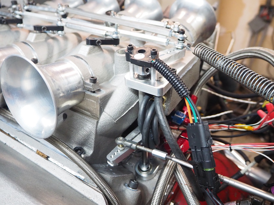
The dyno mule has been using the MS3-Pro EFI system to control the engine's timing, with the crank and cam sensors and no distributor, so it was easy to just add the fuel system from the MS3-Pro to run the injectors. This setup is low compared to all the other intakes, and uses long runners, so it was expected to make a lot of low and midrange torque, but not as much top end horsepower as some of the other intakes. Also, as an individual runner intake, it was going to be peaky (In fact the power and torque curves from this intake look very similar to the Hilborn setup I ran on my SOHC years ago). But it started right up on the dyno, with only real issues being getting the throttle linkage adjusted correctly. This intake idles with the butterflies almost completely closed; if they are cracked open even a little, like maybe .040", the engine is right up at 2500 RPM. Hilborn used to recommend setting the idle so that a strip of newspaper would barely slide out of the gap between the throttle bore and the throttle plate, and that is probably just about right for this setup.
The dyno curves for the tunnel ram and the IR intake are shown below. The peaky nature of the IR intake is evident, especially below 4500 RPM. But it is making huge torque down there, almost 600 foot pounds at 3000 RPM and nearly 700 foot pounds at 3800. During the dyno pull, as the peak at 3800 approached, the sound from the engine was unbelievable! You could really tell the power was increasing. The IR intake actually made the most torque of any of the intakes, edging the tunnel ram at 767 foot pounds. As expected it flattened out after about 5500 RPM, but to my surprise it started gaining again at the higher engine speeds, and actually surpassed the tunnel ram's power at 7000 RPM. It looks like it's headed for another peak at a higher engine speed.
In contrast the tunnel ram made smooth power up to peak in the 6300-6500 RPM range. It made a remarkable 763 foot pounds of torque, and 865 HP, before it started falling off. The manifold behaved nicely on the dyno, no special tuning or adjustments necessary. It would be a great bracket race manifold, for someone who wants to lauch at 5000 RPM and shift at 6500-7000, to go through the lights at 7000+.

So, FINALLY after a year and a half of concerted effort, I'm ready to go to production tooling with these intakes. I will be sending out a summary to my customers and asking for their input on which intake manifolds they may be interested in. If there is little or no interest in one of them, I will probably just produce five instead of all six. We'll see what everybody says. I'm currently building a 390 stroker engine that will use a set of my SE heads, and I will be putting the IR intake on that engine. I may go to the low 4V intake for my Mach 1, so that I can put the original hood and shaker scoop back on it. And I want to use that tunnel ram on something, just not sure what yet...