Show Posts

This section allows you to view all posts made by this member. Note that you can only see posts made in areas you currently have access to.


Messages - jayb

Pages: 1 2 [3] 4 5 ... 513
31
Private Classifieds / Re: Complete fresh 427 hi riser for sale
« on: May 09, 2026, 10:15:18 PM »
Classified ads require an asking price, please put one in your ad.  Thanks!

32
FE Technical Forum / Re: 605" SOHC, 1040 HP
« on: May 09, 2026, 07:07:10 AM »
That's not a bad idea Joel, I will look into that.  I need to feel confident in this thing before I take it back out on the track...

33
FE Technical Forum / Re: starters
« on: May 09, 2026, 07:04:50 AM »
I've had some issues with high compression engines and Powermaster starters.  If you look at them carefully during operation you will see that the starter gear does not full engage the gear on the flywheel; it only goes 2/3-3/4 deep into the teeth.  I've taken them apart in the past and machined the mounting flange so make it thinner, so that the entire gear engages the flywheel teeth.  But I've had better luck with the RobbMc starters, which don't have this problem, and also offer the pinion support like a factory starter.  I think if you are running 12:1 or more on a big engine, you should be leaning towards the RobbMc starter.

34
FE Technical Forum / Re: 605" SOHC, 1040 HP
« on: May 08, 2026, 05:32:27 PM »
You would think I would have seen some oddball wear on the rod bearings but there never was; in fact they looked perfect on teardown, even the time the rod broke.  The coating was still on the bearings!  That dry sump setup really kept those bearings in great shape.

35
FE Technical Forum / Re: 605" SOHC, 1040 HP
« on: May 08, 2026, 08:46:42 AM »
I spent the afternoon yesterday putting a few more dyno pulls on this engine to try to sneak a little more power out of it.  I used the two wideband O2 sensors on the dyno to monitor the individual A/F numbers of each cylinder; the headers have O2 sensor bungs in each primary tube, about 8" down from the flange.  I only found two of the cylinders that were significantly off from the 12.5-13.0 A/F target, and they were off in different directions, so after correcting them with the injector trim feature in the EFI ECU, I ran some more tests hoping for a little more power, but there was nothing more there.  The only thing I did notice was that the curve stayed flatter up at the top end, and held over 1020 HP out to 7500.  I was reluctant to go any higher than that; there's a  lot of piston speed there at 7500 with that big stroke.

I put an update with all the specs in the dyno section of the site.

Last night I reluctantly got started on the teardown, which I should be able to get done over the weekend.  Then the rods and heads are going in for the checks/updates previously mentioned.  Hopefully it won't take too long at the shop and I can get this engine back together in June.  A few more dyno pulls for checks and then I can get it in the car.  My 69 Shelby clone is waiting...

36
FE Engine Dyno Results / 605" SOHC, 1040 HP, 846 Tq
« on: May 08, 2026, 08:35:38 AM »
Performance Summary:
      Cubic Inches:      605         Dyno brand:  Superflow 901
      Power Adder:     None          Where dynoed:  FE  Power
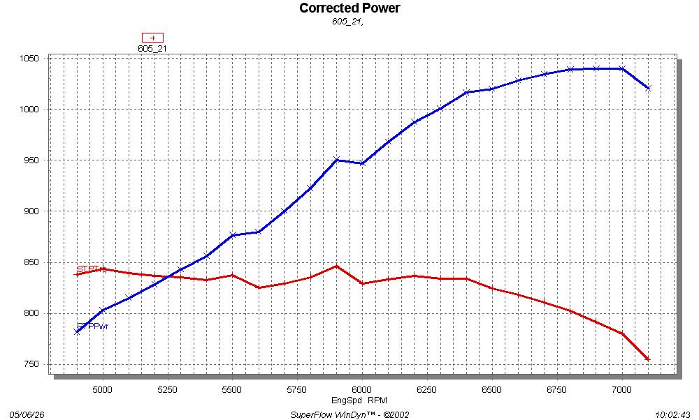
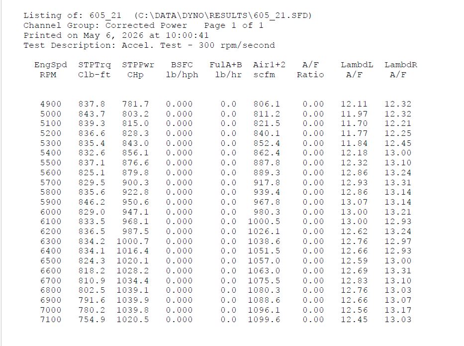
      Peak Horsepower:  1039.9  @ 6900
      Peak Torque:  843.7@5000, 846.2@5900 (?, may be a blip in the curve)

Horsepower and Torque Curves:


Engine Specifications:
   Block brand, material, finished bore size, other notes:

Shelby aluminum block, 4.500" bore, offset bored to a 4.700" bore spacing,
Darton sleeves with O-ring grooves, SCE O-rings for copper head gaskets

     
   Crankshaft brand, cast or forged, stroke, journal size:

Crower billet crank, throws moved to line up with the spread bore spacing, stock main
journal size, 2.100" rod journal size

     
   Connecting Rods brand, material, center to center distance, end sizes, bolts:

Crower billet SBC rods, 6.625" length, .927 pins

   Piston brand, material (caster, hypereutectic or forged), dish/dome volume, static CR:

CP forged pistons, designed to work with offset bore (the dome on
the pistons is moved to line up with the heads), 13:1

   Main Bearings, Rod Bearings, Cam Bearings brand and size:

125M Main bearings, Clevite rod bearings

   Piston rings brand, size, other notes:

Total Seal rings, steel top 0.9mm, Napier 2nd 0.9mm, 3mm oil ring
standard tension

   Oil Pump, pickup, and drive:

Peterson Fluid Systems 6 stage dry sump pump

   Oil pan, windage tray, oil filter adapter:

Custom fabricated oil pan and windage tray

   Camshaft brand, type (hyd/solid, flat tappet or roller), lift and duration (adv and @.050")

Comp SOHC cams, 323/315 advertised, 296/288 @ .050, 114 LSA, .739/.739 lift

   Lifters brand, type:

Not required ;-)

   Timing chain and timing cover:

Pond timing cover, gears, and chain

   Cylinder heads brand, material, port and chamber information:

No-name heads,  welded to raise intake and exhaust ports, fully ported

   Cylinder head flow in cfm at inches of lift (28" H2O pressure drop):
      Intake               Exhaust
      .100               .100
      .200               .200
      .300               .300
      .400               .400
      .500               .500
      .600               .600
      .700   465            .700   330
      .800               .800

   Flow bench used, location:

Superflow, R&R Performance

   Intake valve brand, head size, stem size:

Trick Titanium, 2.35", 11/32"

   Exhaust valve brand, head size, stem size:

Trick Titanium, 1.900", 11/32"
   
   Valve springs brand, part number, specs:

PAC springs, 190 on seat, 540 open

   Retainers and locks brand, part number, specs:

PAC tool steel retainers, Manley locks

   Rocker arm brand, type (adjustable or non-adj), material, ratio

FE Power non-adjustable rockers, stock ratio (~1.3:1)

   Rocker shafts and stands, brand, material:

Precision Oil  Pumps shafts

   Pushrods brand, type, length:

Just say NO to pushrods.

   Valve covers, brand, type:

Blue Thunder

   Distributor brand, advance curve information:

Distributorless ignition, crank and cam sensors, 38 total

   Harmonic balancer brand:

ATI

   Water pump brand, type (mechanical or electric):

CVR Electric Pump with FE  Power adapters

   Intake manifold brand, material, porting information:

Fabricated sheet metal intake

   Carburetor(s) brand, type

Accufab Dominator throttle bodies (2), Ford Racing 80# Injectors

   Exhaust manifolds or headers brand, type:

Custom built headers for chassis, 2-1/8 to 2/1/4 to 2-3/8 step,
merge collectors with 3" choke

37
Let me know Joe, I do have one set of the tunnel port heads finished and in stock - Jay

38
FE Technical Forum / 605" SOHC, 1040 HP
« on: May 06, 2026, 11:05:19 AM »
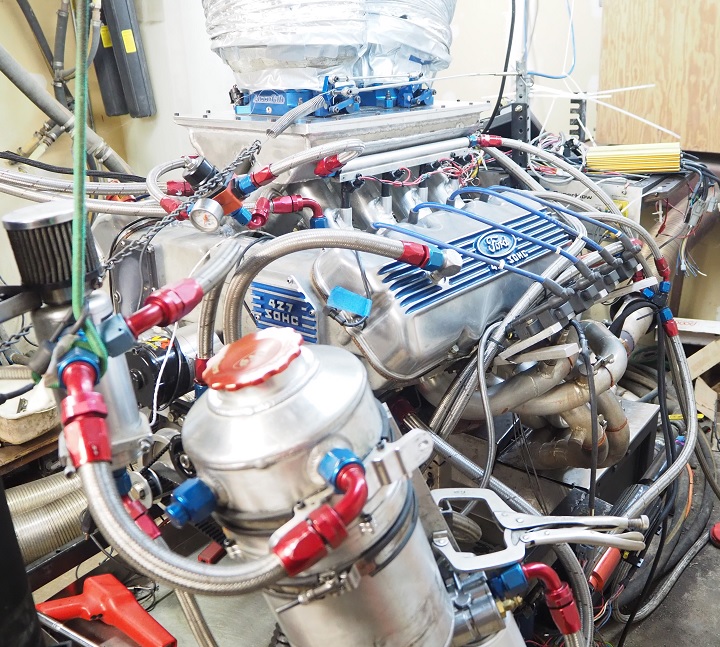
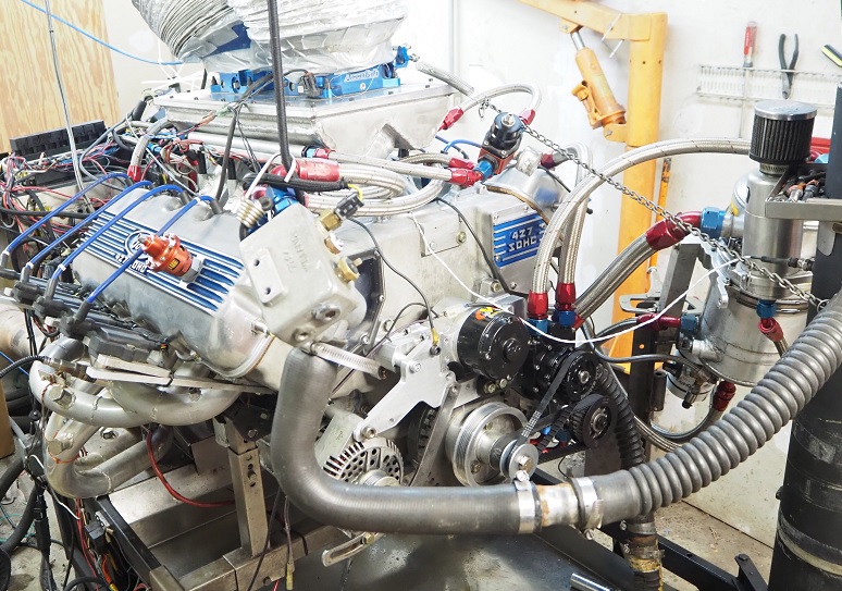
This is a project that has been in the works for about 10 years.  Here's a couple photos of the engine
on the dyno:


A couple pics of the best dyno pulls so far:


This is basically the same engine that I ran in my Galaxie at Drag Week in 2009, and that I
also ran in my Shelby clone in 2011, and 2014-2016.  It is now 605 cubic inches and well over
1000 HP, but it has had a lot of problems along the way.  Here is some history:

Back in 2009 I was still attending Drag Week every year and had found that the biggest cubic
inch engines made competing at the event and winning much more likely.  With a lot of cubes
you can dial back the radical valvetrain and compression requirements and still make enough
power to be competitive, so I wanted to build an FE that was as large as possible.  I had
just competed in Drag Week 2008 with my 520" SOHC Galaxie, but after repeated rocker arm failures
I had not been able to finish the event.  T&D had just come out with their new rockers which
looked to be a lot better than the Dove, RAS, and Ford rockers I had been using.  So I wanted
to head back to Drag Week with the Galaxie again, but with better rockers and more cubes.

I remember talking on the phone with Wes Adams about this, and he gave me the idea of spreading the
bore spacing of the block, in order to make a bigger bore. I was able to get a
partially machined aluminum block from Shelby, and had my local shop rebore it to 4.70" bore
spacing, up from the normal 4.63".  With O-rings in the sleeves and copper head gaskets I was
able to go to a 4.500" bore.  Along with a 4.6" stroke billet crank from Crower, the short
block was up to 585 cubic inches.

On the dyno the engine made 935 HP with Hilborn injectors converted to EFI, and at Drag Week
2009 the Galaxie ran low 9.50s and won the class.  I made two passes on the last day, and was
lucky that the first one was good enough for the win, because I lost a T&D rocker on the second
pass.  They had been brand new with only 50 miles on them when I left for the event.

I skipped Drag Week 2010, went back in 2011 with the engine in my 69 Shelby clone, but dropped
out after the first day due to water in the oil, related to the offset boring on the block (the offset
boring had opened up the casting on a couple cylinders, so that the back of two sleeves were exposed
to the water jacket.  I used a chemical sealant to seal up the block, but it gave up between the first
and second tracks).  Missed the event again in 2012, went with the Mach 1 in 2013, and back with the
SOHC and the Shelby clone in 2014.  That year, the #5 Crower billet rod broke during the Drag Week
test and tune, and I was out of the event again.

The rod failure was a big surprise.  I had not scrimped on the quality of the bottom end components
and wondered if it was just a defective rod, or if there was something else going on.  I sent the rod
to Crower for analysis, and never heard a thing back.  Eventually I had the block
repaired and rebuilt the engine, went back to Drag Week in 2015 and 2016, finishing first and second in
class respectively. I dealt with multiple rocker failures both years, and on teardown after 2016 I found
the #5 connecting rod cracked and ready to fail; I was lucky it hadn't let go.  So obviously the
connecting rod that broke earlier was not defective; there was just something about the engine that
was hurting the #5 rod.

So, ten years ago I was faced with two major problems with the engine, the repetitive rocker arm
failures and the #5 connecting rod failures.

The rocker arm problem was addressed with my own design rockers, which I designed and started
building a few years later.  They feature full time pressure oiling to a bushing in the roller wheel,
rather than relying on oil splash to needle bearings like all other SOHC rockers do.  At this point
I'm pretty happy with that solution.

The #5 rod is a head scratcher though.  Due to the spread bore spacing on the block, the #1, #4, #5, and #8
rods are not centered in the piston; they are offset by the amount of the change in bore spacing, 0.105". 
But if this was the problem, why was the issue with the #5 rod only?

There was no good answer to this question.  I worked with Blair on this and he ordered a Crower
crank for me that had the throws offset to line up properly with the spread bores.  The hope was that this
would solve the rod problem.  I also wanted to move up to a 4.75" stroke, so Blair also specified 2.100"
 journals and small block Chev Crower rods that are supposed to be good for over 1000 HP.  I'm a little
skeptical about that, but I guess we'll see; so far so good.  With the 4.75" stroke and the 4.50" bore,
the engine is 605", probably the biggest cube FE that has ever gone together.

Various other projects came and went over the last several years, delaying my progress on this engine.  I finally
started getting it together in February.  In addition to the new crank and rods, and the rockers, I updated the
cams and valves for the engine, and put in a new dry sump pump (the last one was trashed by needle bearing shards
after rocker arm failures at Drag Week 2016).

It was good to finally get the engine up and running on the dyno.  In 2016 it made 1002 HP, so it has shown a nice
increase in power so far.  I have more dyno work to do on it, with some more tuning I think it might pick up a little
more; we will see. 

Then, unfortunately, I have to tear it all down.  I need to mag the rods and make sure that the crack on the #5 rod
is not coming back again.  Another thing I recently learned, courtesy of Ferrea, is that titanium valves do not mesh well with
very hard valve seats.  The heads I have were built with powdered metal seats, which are very hard.  To be safe
I will get them replaced with ductile iron seats.  I want to do everything possible to put this engine together
one last time, so I don't have to tear it apart for repairs again. 

I put a post in the dyno section with all the details on this engine.  With luck I will have it
reassembled and back in the car by the end of the summer.  It would be nice to get back on the track again...

https://fepower.net/simplemachinesforum/index.php?topic=13176.0


39
Member Projects / Re: 67 Mustang Pro Street
« on: May 04, 2026, 08:35:58 AM »
Looks great Carl!

40
Non-FE Discussion Forum / Re: e mail change
« on: April 21, 2026, 02:48:45 PM »
Email  me with your new  email address and I will update it for you - Jay

41
Not cheap enough; based on the pricing shown in his video one of my intake adapters would be >$9,000 to print.

42
FE Technical Forum / Re: Truck headers for Dyno
« on: April 14, 2026, 03:57:06 PM »
I  think the truck headers you mentioned will work - Jay

43
Every time the topic of plastic intakes comes up I have to laugh about my own experience with them.  Back in 2017 I bought a large 3D printer, with the idea that at some point I could print a plastic intake and test it on the dyno.  I had purchased a spool of PLA plastic printing filament and soaked it in ethanol fuel and race gas, and it held up well for a week, so I bought the printer knowing that at least the fuel wasn't going to melt the plastic.  When I finally got around to doing my cylinder heads a few years later, I started designing and printing intakes for them.

After printing a sheet metal style intake, I put it on my dyno mule and tried to run it.  It was fitted with two big Dominator carbs.  To this day I regret not having a camera in the dyno room to video the results.  When I tried to start the engine at an idle it wouldn't catch, probably (I thought) because of the big plenum in the intake.  So I pumped the throttle a few times, opened it up a little, and hit the starter.  After a couple cranks there was a huge, loud explosion and fireball!  The carbs ended up hanging over the left valve cover, on fire.  The plastic in the manifold was blown all over the dyno room, totally shredded.  If I'd had a camera running, I'd have a million hits on youtube with that video; the explosion was absolutely spectacular!

Red plastic from the intake was blown all through the induction system too.  I had to pull the heads, and pick little bits of plastic out from between the pistons and the top ring on a bunch of cylinders.  Five years later I was still finding little bits of red plastic in the corners of the dyno room from that explosion.

Being a sucker for punishment,  I printed another intake, this time a low 4V intake.  After it was printed I checked to make sure it was airtight.  It was NOT; water poured into the intake would leak out between the layers of the 3D printed plastic.  Obviously, my first intake had a huge vacuum leak that caused the problem.

I took the new intake and coated it on the outside with garage floor epoxy to seal it up.  Then after getting the engine back together I tried again, and this time the engine ran great with the 3D printed plastic intake.  Over the next couple years I kept printing and testing intakes; it only cost about $200 in plastic to print them, and I could make changes to the design on the computer, so it turned out to be the great development tool that I had originally envisioned.  In fact, the 8V tunnel wedge style intake went through three revisions in plastic.  The first one made only 825 HP, but the third one, which was an improved design, made 875.  I was really pleased with how easy it was to tweak the manifolds on the computer, and then get real life data from the dyno which showed any improvements.  I was able to tweak all the manifolds for my cylinder head package to optimize their performance.

I did have one other minor explosion along the way, with another sheet metal style intake.  Despite being epoxy coated, it gave a small backfire that knocked a hole in the plenum.  That huge plenum was just a bomb waiting to go off when you added fuel.  Fortunately, that one was no problem to clean up.

Occasionally I get folks who want to buy a plastic intake from me, and run it on the street.  I won't sell them one; a single backfire will damage the intake and potentially spread shrapnel through the engine.  I think even a modern automotive plastic intake would be a big risk to run on a performance engine, unless it was EFI and the timing and throttle settings were dialed in perfectly.  That is how the major manufacturers get away with plastic intakes; best for folks like us to stick with aluminum.

44
They are the first foundry I contacted back in 2011, about doing my intake adapters.  I asked for an NDA, because I didn't want them to steal the idea.  The foundry guy turfed it to some business guy, who talked and talked and never signed the one I offered, or offered me his own.  Left a pretty bad taste in my mouth, so I won't go back there.  They are too far away anyway...

45
The Calliope project is not really mine, I'm just doing some of the machine work.  That one should continue, Dan is a lot younger than I am LOL!

Pages: 1 2 [3] 4 5 ... 513