Author Topic: FE Power Cylinder Heads on the Dyno, Round 2  (Read 11857 times)

0 Members and 1 Guest are viewing this topic.

jayb

  • Administrator
  • Hero Member
  • *****
  • Posts: 7405
    • View Profile
    • FE Power
FE Power Cylinder Heads on the Dyno, Round 2
« on: January 10, 2021, 01:01:22 PM »
Got some better results this time.  This will be a long post, so here's a quick summary:

- The rocker arm breakage problem appears to be solved, the 4140 steel rockers held up without any trouble.
- RE (Raised Exhaust) heads were on the engine, still in unported condition.
- The 4V intake and 1150 Dominator carb peaked at 857 HP and 719 lb-ft of torque.
- The 8V intake and dual Dominator carbs peaked at 860 HP and 734 lb-ft of torque.
- The engine still doesn't want to make additional power past about 6500 RPM; not sure why at this point...
- Will be testing the SE (Stock Exhaust) heads this week.

It has taken way too long to get to this point, but finally last week I started getting the engine back together to run more dyno tests.  I'd had it torn down to the short block because after the last dyno session I thought I had bent a valve, but that turned out not to be the case.  Instead, I discovered a coil bind problem on the #8 exhaust valve, where the inner spring wouldn't fit completely up on the retainer.  This led to a coil bind condition on #8 exhaust, which was why it was jamming the adjuster back into the aluminum rocker.  I ended up having all 16 retainers machined to fit the springs better, because they were all pretty tight.  After getting the new rocker arms finish machined, I reassembled the heads and got the engine back together.

After installing the heads and the first pair of rockers I measured for pushrods and ordered a set from Smith Brothers.  I had ordered them with .040" restrictors in the pushrods, but when they arrived they didn't have the restrictors installed.  I decided to run them anyway, so after assembling the engine I pre-oiled and watched for oil flow onto the retainers.  Sure enough, a couple of them got oil much faster than the others, and it seemed to take longer to get oil to all 16 rockers than it did the first time I ran this engine (with the aluminum rockers and different pushrods that DID have the restrictors).  So I'm thinking that the restrictors are probably a pretty good idea on this setup.

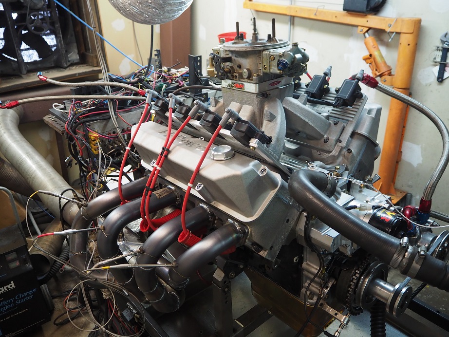
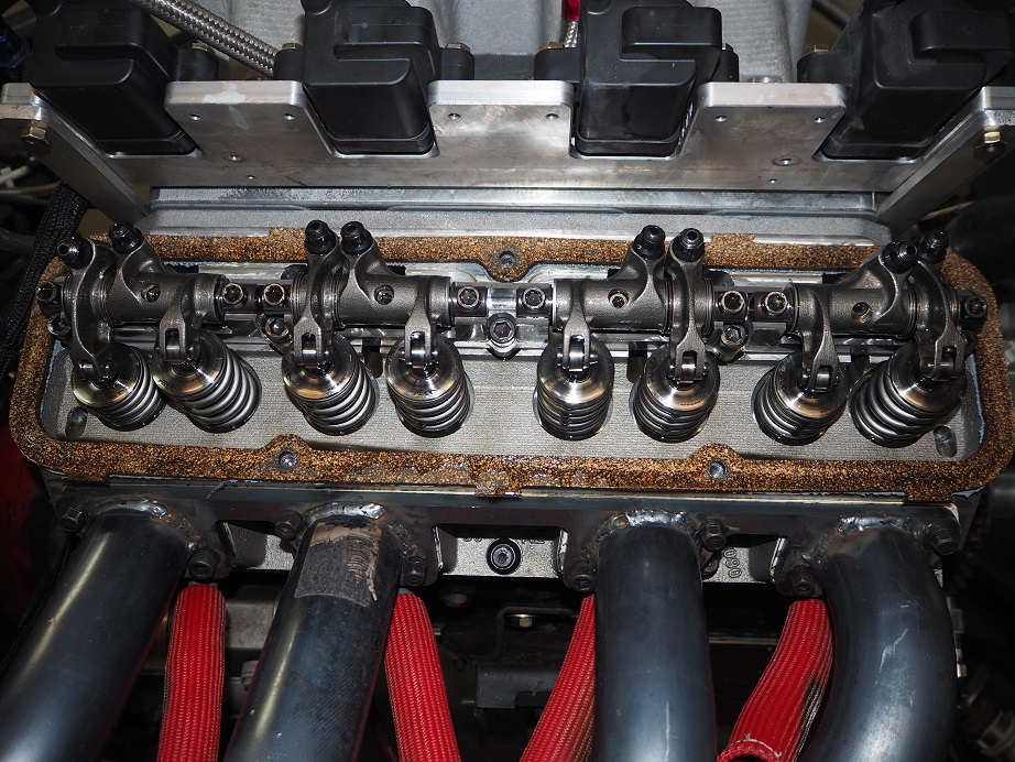
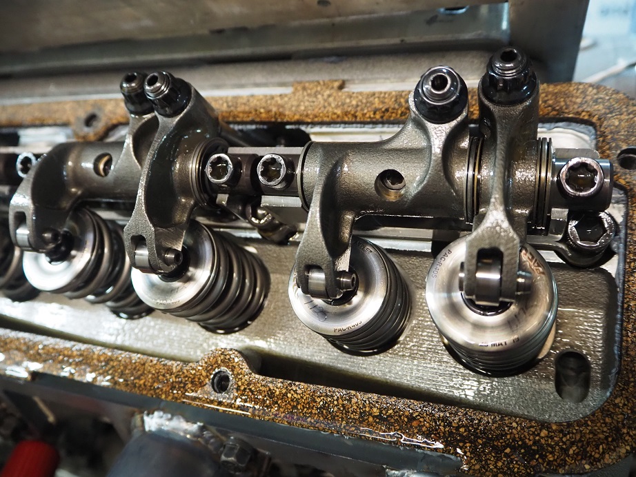
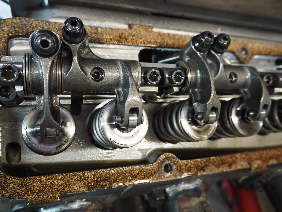
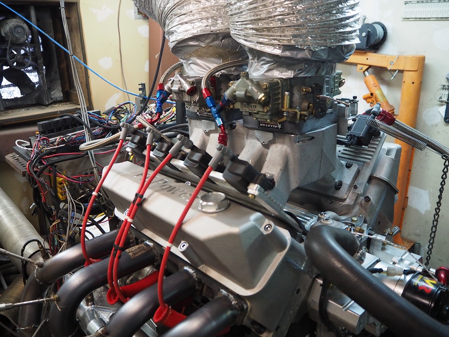
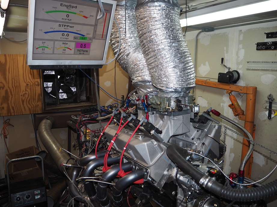
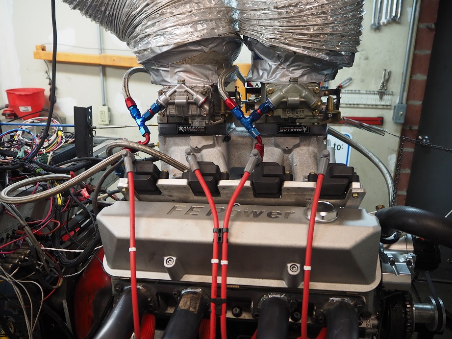
After pre-oiling I got the 510" engine the rest of the way back together.  Here's a picture of the engine on the dyno, with the 4V intake installed, and also some pictures of the rocker arm setup:


There were several changes to this engine on this go-around, most notably the rocker arms.  However, I had also sent the intake adapter and both intake manifolds down to Joe Craine for flow testing and some touch up work.  Joe found that the 4V intake was pretty good as is, but he did some cleanup in the plenum and on some of the runners to get them all matched up to flow the same.  On the 8V intake, Joe found that it needed quite a bit more work than the 4V; he did a lot of work smoothing the entrance of the runners into the plenum.  I am going to incorporate the changes Joe made into the designs of the intakes, so that the next castings come out with his modifications.  Joe has also offered to do some different porting on the 4V intake, so I'm going to send that one back down to him later this month, and then test again when I get it back.  I think it's really cool that I can get these parts modified to improve the power numbers, and then just build the modifications into the castings.  The power of 3D printing...

One other change to the intakes is going to be making them one piece rather than two piece; Joe thought that any decent porting guy could get into the runners of the intakes with no problem, so having the intake cast in two separate pieces is not really necessary.  That will reduce some CNC machining time here, which is a good thing.

The other major change I had decided to make was to the stepped headers for the RE heads.  My original set of headers used 2" pipes, 16" long, into 2-1/8" pipes 8" long, into 2-1/4" pipes 8" long, and then into a slip-on merge collector with a 2-3/4" choke and 4" outlet.  I had been thinking that the primaries might be too small, but I wanted to stick with the existing collector.  So, for a couple days before I started the testing, I built another set of primaries.  This set used 2-1/8" pipes 16" long, into 2-1/4" pipes, also 16" long. 

Thursday this week I finished assembling the engine and getting it ready to run.  My friend and Engine Masters competitor Royce B had come to help; it was good to have another set of qualified eyes on this process.  We started with the original, smaller headers, because I wanted to do a back to back comparison with the new headers when that time came.  Thursday night we left the shop with the engine basically ready to run.

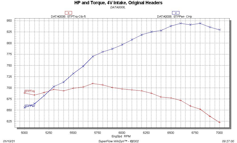
Friday morning we got started with the dyno pulls.  It was a somewhat cold, high pressure day in Minnesota, and the air going into the engine was only about 58 degrees, so it led to a very small correction factor for the dyno, at 1.6%.  We made several  pulls from 3000 to 5000 RPM, to get the jetting adjusted properly in the carb.  After we got A/F numbers in the high 12s and low 13s, the engine was making about 10 more HP at 5000 RPM than it had been during the first dyno session in September.  So, we started increasing the RPM range in 500 RPM increments.  By the time we got to the 4500-6500 RPM pull, we were getting pretty good results.  I was very pleased with the torque number at about 710 lb-ft, and the HP number was up to 847.  I had been figuring about 850 HP with the 4V intake, so that was right on expectations.  Then, we ran the 5000 to 7000 RPM pull, but again, just like last time, the power curve just flattened out at 6500.  So 847 HP was all we got, even with more engine speed.  Here is a graph of the dyno results at this point:


We had still been running the old headers.  We let the engine cool for an hour before we changed to the new headers, to avoid the usual burns.  I was curious whether I had wasted a bunch of money on mandrel bent tubing, and a bunch of time building the new headers, or whether they would improve the situation.  Bottom line, the new headers were a win, to the tune of about 10 HP and 10 lb-ft of torque across the entire RPM range.  Here is a graph showing the results of the header swap:


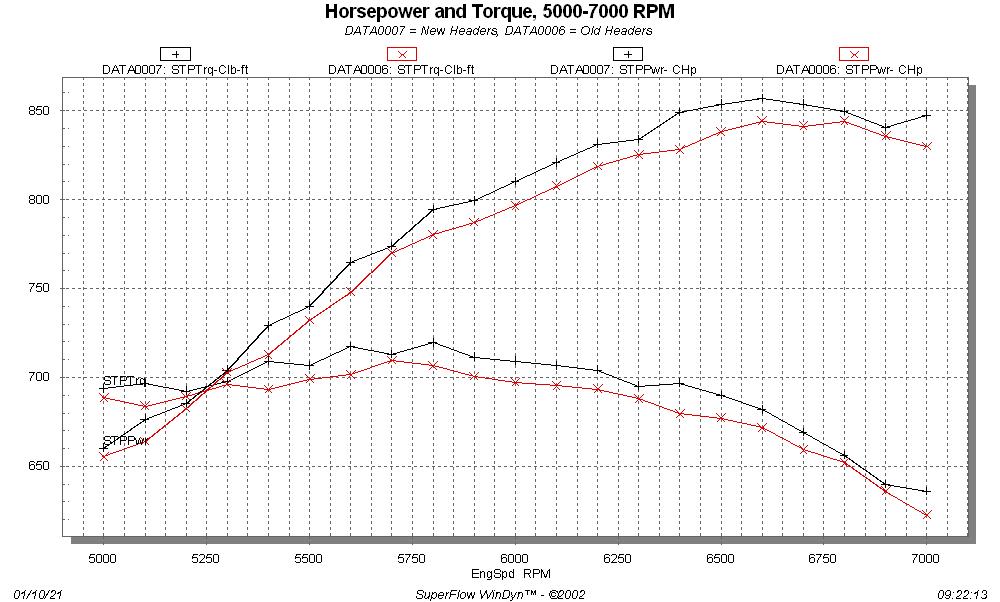
So, best results for the 4V intake was 857HP and 719 lb-ft.  The HP number exceeded my target by a few HP, and I was especially pleased with the torque number; to get past 1.4 lb-ft per cubic inch is a great result. 

Royce and I spent the rest of the day on Friday removing the 4V intake and setting up the 8V intake for testing.  I had originally tested this intake with a pair of 850 center squirters, but Royce brought up his 1050 Dominator, so we thought why not just go ahead with the two Dominator carbs instead.  How those were fit onto the intake is rather interesting.  The 8V intake manifold is drilled with two 4150 carb bolt patterns, one for putting the carbs in line, and one for putting the carbs sideways.  When the 8V intake was down at Joe's, he discovered that using that bolt pattern, a Dominator flange carb would fit if you just cocked the carb a little sideways on each pad.  So, using two of the holes for the inline 4150 pattern, and two of the holes for the sideways 4150 pattern, a Dominator carb will fit on the intake.

This actually turned out to be somewhat of a challenge, because of the brand new BENT carb studs that I received from Summit Racing.  Must have been Chinese junk, because out of three packs, there wasn't one stud that was completely straight, and some of them were bent really bad.  ARP next time, I guess.  Regardless, we eventually got both Dominator carbs put onto the intake with 1" open spacers underneath.  We had to put together some new fuel lines, because the ones from the 850 center squirters weren't long enough, and I had to make up a new linkage setup, but finally at the end of the day on Friday, we had the 8V intake installed on the engine and were ready to run.  Here are some pictures of the engine with the 8V intake and dual Dominators installed:


Saturday morning we got started with the tuning by running several pulls from 3000-5000 RPM.  At first we were way rich, and we ended up leaning both carbs down.  However, my 1150 Dominator carb has power valves, and Royce's 1050 Quick Fuel carb doesn't, so we kept his jetted several steps richer than mine before we finally got the A/F numbers that we wanted.  We saw that at 5000 RPM, the 8V setup was up significantly from the 4V setup.  We also noticed that the engine started more easily with the 8V setup.

By the time we got to a 4500-6500 RPM pull, things were looking very promising.  Peak torque was up significantly, to over 730 lb-ft, and the HP numbers were looking good.  It is always dangerous to rely on the first number, or the last number, of any dyno pull data, but the last number for that pull looked like we were on the way to 900 HP.  Here's a graph of those results:


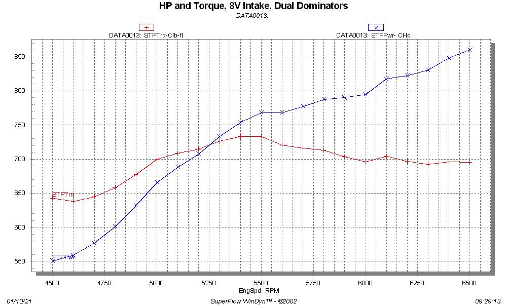
But on the next pull from 5000 to 7000 RPM, to our surprise and dismay, the curve flattened out again past 6500.  860 HP and 734 lb-ft were the peaks. 

We speculated endlessly on the cause of this behavior.  If I didn't have all the dyno data I'd say it was valvetrain, but on the dyno you can look at the airflow into the engine, and for both the 4V and 8V intakes, air flow continues to increase linearly past 6500 RPM, all the way to 7000 RPM.  With a valvetrain issue you will usually see the airflow go choppy, but that was not the case.  A/F is also pretty steady from 6500 to 7000 RPM.  So it doesn't seem like we were entering a valve float condition (which would be hard to believe with the valve springs I'm running anyway).  Our best guess is that the engine just doesn't like this cam, but it is certain hard to say for sure.

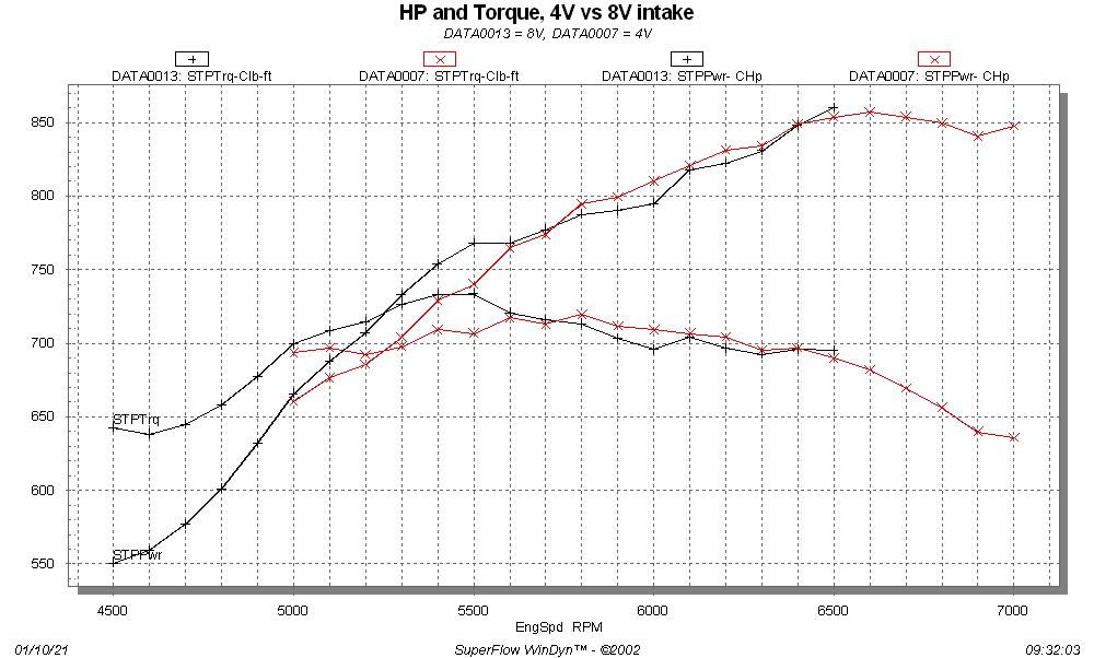
In any case, here is a graph of the 4V intake results vs the 8V.  Notice the big fat torque advantage that the 8V intake has from 5000 to 5600 RPM.


Royce and I had a couple of other guys from the forum join us on Saturday afternoon, and I took this opportunity to check the dyno's calibration while everyone was there watching.  After 15 years of dyno experience and over 100 different engines dynoed (including over 30 of my own), I tend to be a little bit suspicious of the some of the dyno numbers that I've seen from other dynos, and I know for a fact that some of them read high.  I wanted to be sure that these numbers were legit, so we checked the weather data that the dyno uses against the NOAA barometric pressure and my stand alone weather station for temperature, against the dyno readings, and they were consistent.  Then I loaded up the torque link on the dyno with the weight bar provided by Superflow, and added enough weight to get to 880 lb-ft of torque in several steps.  We found that the dyno torque reading was accurate within 0.5% all along the way.

At this point, I'm in the process of tearing down the engine and setting it up to run the SE (Stock Exhaust) heads.  I have to transfer all the valves and the valve springs/retainers/locks from the RE heads to the SE heads before I can get the engine back assembled, so it will be later in the week before I'm running again.  I think I will also start looking at a different cam, just as a test if nothing else.  I think that the as-cast heads are capable of supporting 900 HP, but we haven't got there yet, so I'll be working on that too.  I will add the results from the SE heads to this thread when I have them, towards the end of the week.
Jay Brown
- 1969 Mach 1, Drag Week 2005 Winner NA/BB, 511" FE (10.60s @ 129); Drag Week 2007 Runner-Up PA/BB, 490" Supercharged FE (9.35 @ 151)
- 1964 Ford Galaxie, Drag Week 2009 Winner Modified NA (9.50s @ 143), 585" SOHC
- 1969 Shelby Clone, Drag Week 2015 Winner Modified NA (Average 8.98 @ 149), 585" SOHC


My427stang

  • Hero Member
  • *****
  • Posts: 3929
    • View Profile
Re: FE Power Cylinder Heads on the Dyno, Round 2
« Reply #1 on: January 10, 2021, 01:25:54 PM »
Jay, are you willing to share cam specs and installed position?

Setup looks very nice BTW, nice work
---------------------------------
Ross
Bullock's Power Service, LLC
- 70 Fastback Mustang, 489 cid FE, Victor, SEFI, Erson SFT cam, TKO-600 5 speed, 4.11 9 inch.
- 71 F100 shortbed 4x4, 461 cid FE, headers, Victor Pro-flo EFI, Comp Custom HFT cam, 3.50 9 inch

Joe-JDC

  • Hero Member
  • *****
  • Posts: 1490
  • Truth stands on its own merit.
    • View Profile
Re: FE Power Cylinder Heads on the Dyno, Round 2
« Reply #2 on: January 10, 2021, 01:26:00 PM »
Sounds like you need a matching pair of 1450 Dominators.  For the heads to still be as cast, 857 hp on a single 4V is great.  Joe-JDC
Joe-JDC '70GT-500

WConley

  • Hero Member
  • *****
  • Posts: 1160
  • No longer walking funny!
    • View Profile
Re: FE Power Cylinder Heads on the Dyno, Round 2
« Reply #3 on: January 10, 2021, 01:32:28 PM »
Cool stuff Jay!!

An easy experiment would be to retard your existing cam and watch how much the torque curve shifts up.  If you're still running out of breath at 6500, it's a good clue that something else is going on.
A careful study of failure will yield the ingredients for success.

Gregwill16

  • Sr. Member
  • ****
  • Posts: 468
    • View Profile
Re: FE Power Cylinder Heads on the Dyno, Round 2
« Reply #4 on: January 10, 2021, 01:36:43 PM »
Very impressive Jay. You are an FE mad scientist!

Gaugster

  • Sr. Member
  • ****
  • Posts: 396
    • View Profile
Re: FE Power Cylinder Heads on the Dyno, Round 2
« Reply #5 on: January 10, 2021, 01:40:30 PM »
Cool post and thanks for the update!!! Could you advance or retard that cam timing as a means to evaluate if it's the limiting factor? Maybe that's too subtle of a change. Do you monitor exhaust gas temperatures? I might be way off and totally out of my wheelhouse but I thought that was used to judge ignition timing. Again - It's great to read these updates.
John - '68 Cougar XR7 390 FE (X-Code) 6R80 AUTO

jayb

  • Administrator
  • Hero Member
  • *****
  • Posts: 7405
    • View Profile
    • FE Power
Re: FE Power Cylinder Heads on the Dyno, Round 2
« Reply #6 on: January 10, 2021, 02:35:29 PM »
Jay, are you willing to share cam specs and installed position?


The cam is a Bullet cam that I got from Blair for a different application.  Advertised duration is 319/334, duration at .050 is 285/292, gross valve lift is 0.880" on both lobes, and hot lash is .028/.030.  LSA is 112, and it is installed at 110.
« Last Edit: January 10, 2021, 02:40:12 PM by jayb »
Jay Brown
- 1969 Mach 1, Drag Week 2005 Winner NA/BB, 511" FE (10.60s @ 129); Drag Week 2007 Runner-Up PA/BB, 490" Supercharged FE (9.35 @ 151)
- 1964 Ford Galaxie, Drag Week 2009 Winner Modified NA (9.50s @ 143), 585" SOHC
- 1969 Shelby Clone, Drag Week 2015 Winner Modified NA (Average 8.98 @ 149), 585" SOHC


e philpott

  • Hero Member
  • *****
  • Posts: 923
    • View Profile
Re: FE Power Cylinder Heads on the Dyno, Round 2
« Reply #7 on: January 10, 2021, 02:37:51 PM »
You just have to find the right cam that the engine likes with the additional air flow . Back when the Pro Stock racer Ron Miller from Lebanon Oh was building engines he used to test seven different camshafts with identical lobes just moved around a little different from each other and always said you can build them identical but some like cams 1 & 2 better while some liked 6 and 7 better, you just have to find out what they like and you Jay are in totally brand new waters ! Good luck with your cam search

jayb

  • Administrator
  • Hero Member
  • *****
  • Posts: 7405
    • View Profile
    • FE Power
Re: FE Power Cylinder Heads on the Dyno, Round 2
« Reply #8 on: January 10, 2021, 02:39:21 PM »
Sounds like you need a matching pair of 1450 Dominators.  For the heads to still be as cast, 857 hp on a single 4V is great.  Joe-JDC

I don't think that would help, Joe.  On the 4V intake I was showing 1.6 inches of vacuum at 7000 RPM, so it seemed like a bigger carb would help.  However, on the 8V intake with the two Dominators, the manifold vacuum was ZERO throughout the pull.  Seems like if it needed bigger carbs, I would have seen vacuum with the 8V setup...
Jay Brown
- 1969 Mach 1, Drag Week 2005 Winner NA/BB, 511" FE (10.60s @ 129); Drag Week 2007 Runner-Up PA/BB, 490" Supercharged FE (9.35 @ 151)
- 1964 Ford Galaxie, Drag Week 2009 Winner Modified NA (9.50s @ 143), 585" SOHC
- 1969 Shelby Clone, Drag Week 2015 Winner Modified NA (Average 8.98 @ 149), 585" SOHC


jayb

  • Administrator
  • Hero Member
  • *****
  • Posts: 7405
    • View Profile
    • FE Power
Re: FE Power Cylinder Heads on the Dyno, Round 2
« Reply #9 on: January 10, 2021, 02:44:26 PM »
Cool stuff Jay!!

An easy experiment would be to retard your existing cam and watch how much the torque curve shifts up.  If you're still running out of breath at 6500, it's a good clue that something else is going on.

I may try that on the next round with the SE heads, Bill, but I don't know if I'll be able to see a definitive change by just moving the cam timing a few degrees.  Easy enough though, with the adjustable timing set, so I should probably try it...
Jay Brown
- 1969 Mach 1, Drag Week 2005 Winner NA/BB, 511" FE (10.60s @ 129); Drag Week 2007 Runner-Up PA/BB, 490" Supercharged FE (9.35 @ 151)
- 1964 Ford Galaxie, Drag Week 2009 Winner Modified NA (9.50s @ 143), 585" SOHC
- 1969 Shelby Clone, Drag Week 2015 Winner Modified NA (Average 8.98 @ 149), 585" SOHC


jayb

  • Administrator
  • Hero Member
  • *****
  • Posts: 7405
    • View Profile
    • FE Power
Re: FE Power Cylinder Heads on the Dyno, Round 2
« Reply #10 on: January 10, 2021, 02:46:47 PM »
Cool post and thanks for the update!!! Could you advance or retard that cam timing as a means to evaluate if it's the limiting factor? Maybe that's too subtle of a change. Do you monitor exhaust gas temperatures? I might be way off and totally out of my wheelhouse but I thought that was used to judge ignition timing. Again - It's great to read these updates.

Exhaust temps all seem to be fine, all are on the same slope and high to low is in the neighborhood of 175F.  I'm seeing about 1150 at the start of the pull and around 1350 at the end.  Looks pretty normal...
Jay Brown
- 1969 Mach 1, Drag Week 2005 Winner NA/BB, 511" FE (10.60s @ 129); Drag Week 2007 Runner-Up PA/BB, 490" Supercharged FE (9.35 @ 151)
- 1964 Ford Galaxie, Drag Week 2009 Winner Modified NA (9.50s @ 143), 585" SOHC
- 1969 Shelby Clone, Drag Week 2015 Winner Modified NA (Average 8.98 @ 149), 585" SOHC


Cyclone03

  • Sr. Member
  • ****
  • Posts: 338
    • View Profile
Re: FE Power Cylinder Heads on the Dyno, Round 2
« Reply #11 on: January 10, 2021, 03:19:34 PM »
I’m sure you moved the ignition timing around just to make sure it doesn’t want some retard on top.

But most likely you’ll need to engage the cam pros.

I’m going to cheat and just ask instead of researching the post. Are there any FE heads that flow what yours do?

Is there a point where what was normal is just out the window,I’m sure the flow bench will get you the max lift numbers,the magic will come from the cam events.

This project is well into ProStock level development ,not to mention having to learn what multiple major changes want.

Might be fun to plug the numbers into one of those cam programs just to see what it spits out.

Maybe take the choke out of the collector?

I wish I was a customer for a set but it sure is great “seeing” the R&D.

Thank You
« Last Edit: January 10, 2021, 03:37:22 PM by Cyclone03 »
Lance H

jayb

  • Administrator
  • Hero Member
  • *****
  • Posts: 7405
    • View Profile
    • FE Power
Re: FE Power Cylinder Heads on the Dyno, Round 2
« Reply #12 on: January 10, 2021, 04:23:24 PM »
As far as I know there are no FE heads as-cast that flow anywhere near what mine do.  I've been able to get a set of Blue Thunder high risers to be close after a major porting effort, those flowed 401cfm at 0.800" lift on the intake.  My ported SOHC heads flow 460 cfm on the intake, which is 40 cfm more than my as-cast heads flow, but stock the SOHC heads only flow around 340.  There is some company making billet FE heads that probably flow more than mine, but they are like $10K per pair.  My heads just have some basic advantages, like a port that is raised almost an inch and a half, and a straight in shot to the chamber.  The downside of course is that no standard FE intake will fit, and no standard FE rocker system will fit.  But if you're building a complete engine anyway, that shouldn't be too much of an issue.
Jay Brown
- 1969 Mach 1, Drag Week 2005 Winner NA/BB, 511" FE (10.60s @ 129); Drag Week 2007 Runner-Up PA/BB, 490" Supercharged FE (9.35 @ 151)
- 1964 Ford Galaxie, Drag Week 2009 Winner Modified NA (9.50s @ 143), 585" SOHC
- 1969 Shelby Clone, Drag Week 2015 Winner Modified NA (Average 8.98 @ 149), 585" SOHC


My427stang

  • Hero Member
  • *****
  • Posts: 3929
    • View Profile
Re: FE Power Cylinder Heads on the Dyno, Round 2
« Reply #13 on: January 10, 2021, 04:32:32 PM »
Jay, did you by chance check lift at the retainer?  Just wondering what the effective rocker ratio ended up to be for intake and exhaust after deflection, etc.

You certainly are getting all of 2x intake flow for HP which is good, but I think there are likely better lobes that could get you there without so much overlap, assuming of course you are getting the lift you expect

I also wonder if you are going supersonic in the port and might need to open up the ports to get a little more with the big inch engine, but think maybe cam first to see.

Just bench racing, but man, nice work again.
---------------------------------
Ross
Bullock's Power Service, LLC
- 70 Fastback Mustang, 489 cid FE, Victor, SEFI, Erson SFT cam, TKO-600 5 speed, 4.11 9 inch.
- 71 F100 shortbed 4x4, 461 cid FE, headers, Victor Pro-flo EFI, Comp Custom HFT cam, 3.50 9 inch

jayb

  • Administrator
  • Hero Member
  • *****
  • Posts: 7405
    • View Profile
    • FE Power
Re: FE Power Cylinder Heads on the Dyno, Round 2
« Reply #14 on: January 10, 2021, 04:58:40 PM »
I didn't check lift at the retainer Ross, but when I get the heads back on the engine I'll try to remember to do that...
Jay Brown
- 1969 Mach 1, Drag Week 2005 Winner NA/BB, 511" FE (10.60s @ 129); Drag Week 2007 Runner-Up PA/BB, 490" Supercharged FE (9.35 @ 151)
- 1964 Ford Galaxie, Drag Week 2009 Winner Modified NA (9.50s @ 143), 585" SOHC
- 1969 Shelby Clone, Drag Week 2015 Winner Modified NA (Average 8.98 @ 149), 585" SOHC


Ghoughton

  • Jr. Member
  • **
  • Posts: 54
    • View Profile
Re: FE Power Cylinder Heads on the Dyno, Round 2
« Reply #15 on: January 10, 2021, 08:31:39 PM »
Impressive results for sure. But I was wondering the same thing as Ross. Maybe the port cross section is a little small for the application. Resulting in a lower peak rpm than expected. Regardless....still very impressive for just getting stared with the testing.

machoneman

  • Hero Member
  • *****
  • Posts: 3853
    • View Profile
Re: FE Power Cylinder Heads on the Dyno, Round 2
« Reply #16 on: January 10, 2021, 09:00:29 PM »
Sounds like you need a matching pair of 1450 Dominators.  For the heads to still be as cast, 857 hp on a single 4V is great.  Joe-JDC

I don't think that would help, Joe.  On the 4V intake I was showing 1.6 inches of vacuum at 7000 RPM, so it seemed like a bigger carb would help.  However, on the 8V intake with the two Dominators, the manifold vacuum was ZERO throughout the pull.  Seems like if it needed bigger carbs, I would have seen vacuum with the 8V setup...

Terrific results Jay!

But, my 2 cents: is it possible that the senors used to collect manifold vacuum data could somehow be wrong? Your note on ZERO vacuum throughout the pull seems suspicious. Put another way, have you ever dynoed ANY engine that had zero vacuum at all points? Just askin'!
Bob Maag

jayb

  • Administrator
  • Hero Member
  • *****
  • Posts: 7405
    • View Profile
    • FE Power
Re: FE Power Cylinder Heads on the Dyno, Round 2
« Reply #17 on: January 10, 2021, 10:07:33 PM »
I have actually, but only with dual carbs and a sheet metal or tunnel ram style intake with a big plenum.  A couple of my big SOHCs and my 530" high riser behaved that way.  I was suspicious of that number too though, so when I saw it I checked to make sure the vacuum line was hooked up to the dyno console, but it was.  So, I believe that data...
Jay Brown
- 1969 Mach 1, Drag Week 2005 Winner NA/BB, 511" FE (10.60s @ 129); Drag Week 2007 Runner-Up PA/BB, 490" Supercharged FE (9.35 @ 151)
- 1964 Ford Galaxie, Drag Week 2009 Winner Modified NA (9.50s @ 143), 585" SOHC
- 1969 Shelby Clone, Drag Week 2015 Winner Modified NA (Average 8.98 @ 149), 585" SOHC


Joe-JDC

  • Hero Member
  • *****
  • Posts: 1490
  • Truth stands on its own merit.
    • View Profile
Re: FE Power Cylinder Heads on the Dyno, Round 2
« Reply #18 on: January 10, 2021, 10:20:06 PM »
I was just looking at my pictures of your tunnel ram, and I believe that the vacuum port placement is suspect for the zero vacuum reading.  I would like to see it installed in the middle between the carb pads just for grins and a double check.  Where it is located now may be a low pressure area out of the air stream.  Even if it were in the middle of the back, not to the side might give a more true vacuum reading.  Also, is it the same diameter (ID) as the 4V?  Joe-JDC
Joe-JDC '70GT-500

frnkeore

  • Hero Member
  • *****
  • Posts: 1135
    • View Profile
Re: FE Power Cylinder Heads on the Dyno, Round 2
« Reply #19 on: January 11, 2021, 01:42:09 AM »
What was the vacuum reading on the first test, with the 8V, 850's?

It also seems like a run with that original, 850 setup might reveal something.
Frank

cjshaker

  • Hero Member
  • *****
  • Posts: 4460
    • View Profile
Re: FE Power Cylinder Heads on the Dyno, Round 2
« Reply #20 on: January 11, 2021, 02:40:20 AM »
I wonder if the exhaust might be working a little too well with that cam at the upper RPM band and over-scavenging the intake charge, pulling some of it out. The SE heads should prove that to be false or a possibility.

Did Joe test the ports up to .900 lift? Any turbulence at all? A little turbulence at those lifts might be more drastic when the airflow starts to reach maximum velocity. I'm not even sure how a flow test could accurately duplicate what happens when you get that high in velocity.

It doesn't seem to be a valve control issue or the numbers would start to get screwy on the top end. Those seem pretty stable, like it's just running out of intake charge. Seems to me, it's just a combo thing. Get the cam to play well with the port, and that 900hp goal is well within reach.
Doug Smith


'69 R-code Mach 1, 427 MR, 2x4, Jerico, 4.30 Locker
'70 F-350 390
'55 Ford Customline 2dr
'37 Ford Coupe

JERICOGTX

  • Sr. Member
  • ****
  • Posts: 336
    • View Profile
Re: FE Power Cylinder Heads on the Dyno, Round 2
« Reply #21 on: January 11, 2021, 06:16:12 AM »
Very nice Jay.

JERICOGTX

  • Sr. Member
  • ****
  • Posts: 336
    • View Profile
Re: FE Power Cylinder Heads on the Dyno, Round 2
« Reply #22 on: January 11, 2021, 06:18:35 AM »
Jay, what is the offset of the Intake rockers?

plovett

  • Guest
Re: FE Power Cylinder Heads on the Dyno, Round 2
« Reply #23 on: January 11, 2021, 06:57:53 AM »
Impressive results for sure. But I was wondering the same thing as Ross. Maybe the port cross section is a little small for the application. Resulting in a lower peak rpm than expected. Regardless....still very impressive for just getting stared with the testing.

CSA is my bet, as well.  I'm no expert, but it's hard for me to imagine the cam being the core problem, causing the power to just stop rising, even if the cam spec's aren't optimal.  The cam looks big enough even if it's particular spec's could be improved upon.  I would think with a suboptimal (but big enough) cam, the hp would keep rising, just not as much as it could with better spec's.  I could be wrong.

850 naturally aspirated hp is no small number.   The engine is over 2 hp per cfm isn't it?

paulie

edit:  looks like right at 2hp per cfm if I got the right numbers.  417 cfm at 0.800" lift?  Just throwing it out there for thought.
« Last Edit: January 11, 2021, 07:08:31 AM by plovett »

Royce

  • Hero Member
  • *****
  • Posts: 777
    • View Profile
Re: FE Power Cylinder Heads on the Dyno, Round 2
« Reply #24 on: January 11, 2021, 09:43:46 AM »
I don't think it is related to the intake.. JDC can comment since he flowed them, but IIRC those intake runners flow a lot of air.

The single 4 with an 1150 carb was pulling over 1000 cfm of air according to the airflow meter on the dyno at over 2 inches of vacuum. I think a bigger carb and maybe a different spacer combo, and the single 4 would have easily out powered the tunnel ram. When everything is optimized I think 900 hp can be reached.

My money is on the camshaft as the cork in the bottle currently.
1955 Thunderbird Competition Coupe Altered Chassis "War Bird" 383 Lincoln Y block 520 hp
1955 Thunderbird 292 275 hp Y Block
1956 Ford Victoria 292 Y block

1957 Mercury 2dr Wagon "Battle Wagon" drag car 
1957 Thunderbird Glass body Tube Chassis drag car 333 cu in 500 hp Ford Y block
1961 Starliner 390/375 clone
1965 GT40 tribute w/FE
1966 Falcon Pro Touring project
Kaase Boss 547. 840 HP 698 Torque  pump gas
1992 BMW V-12 5.0
2001 Lincoln 5.4 4 cam.
1968 Cougar XR7

jayb

  • Administrator
  • Hero Member
  • *****
  • Posts: 7405
    • View Profile
    • FE Power
Re: FE Power Cylinder Heads on the Dyno, Round 2
« Reply #25 on: January 11, 2021, 10:09:51 AM »
I was just looking at my pictures of your tunnel ram, and I believe that the vacuum port placement is suspect for the zero vacuum reading.  I would like to see it installed in the middle between the carb pads just for grins and a double check.  Where it is located now may be a low pressure area out of the air stream.  Even if it were in the middle of the back, not to the side might give a more true vacuum reading.  Also, is it the same diameter (ID) as the 4V?  Joe-JDC

Joe, fittings on both manifolds were the same diameter, and the vacuum hose was the same diameter.  Frank had a good suggestion, to check the old results, and with the two 850s I was seeing 0.5" of manifold vacuum at peak RPM back in September.  One of the pictures in the original post in this thread shows the vacuum line connected to the back of the manifold, so I know I put it on there.  I suppose it is possible that it fell off or got pulled off sometime during the tuning process and that resulted in the zero vacuum reading, but as I mentioned earlier I have seen zero vacuum readings before, so I think it is probably legitimate.

The engine is apart now, getting ready for the SE heads, so I can't do further testing on this until later this week.  I'll probably start with the 8V intake when I do, so I'll make sure I've got the vacuum line connected and we'll see what the readings are then - Jay
« Last Edit: January 11, 2021, 10:27:14 AM by jayb »
Jay Brown
- 1969 Mach 1, Drag Week 2005 Winner NA/BB, 511" FE (10.60s @ 129); Drag Week 2007 Runner-Up PA/BB, 490" Supercharged FE (9.35 @ 151)
- 1964 Ford Galaxie, Drag Week 2009 Winner Modified NA (9.50s @ 143), 585" SOHC
- 1969 Shelby Clone, Drag Week 2015 Winner Modified NA (Average 8.98 @ 149), 585" SOHC


blykins

  • Hero Member
  • *****
  • Posts: 4822
    • View Profile
    • Lykins Motorsports
Re: FE Power Cylinder Heads on the Dyno, Round 2
« Reply #26 on: January 11, 2021, 10:15:20 AM »
My money is on the camshaft as the cork in the bottle currently.

We will find out soon, I just sent in an order for one.

I'm of the same mind and if I'm wrong, a cam change is quicker/easier/cheaper than having the heads ported. 

The existing camshaft has almost 102° of overlap and not near enough duration split for these cylinder heads.  It may be a situation where the overlap is just pushing power out the exhaust.  There are situations where the cam can be much bigger than what's needed, or even bigger than what the heads can handle, and the engine simply doesn't know what to do with it.  I have ground smaller camshafts for guys in the past who were at wits' end trying to figure out how to go faster and have picked them up a tenth. 

As an engine comparison, a 510" Tunnel Port here with much less duration (270/280 @ .050") and 380cfm heads will peak at 7000-7200.  Jay's heads have 30+ cfm of flow over those.

Took me some time with a lobe catalog to find some lobes that were not spring eaters but had the lobe lift large enough to get us where we wanted to be with a 1.75 rocker ratio, while watching coil bind clearance with Jay's valvetrain. 

If the camshaft doesn't let it zing on up, then I would look to the possibility of needing a little more intake port volume for a large engine.  I'm running into this with the TFS heads right now, as they work really well with a ~170-175cc port and will support big horsepower on a smaller engine, but as I'm looking at some 496-505 ci engine builds, I think the port size will be a limiting factor.  Got a set being ported right now to open up the envelope for a 496ci build going on. 

If nothing else, we will get data, and data is always good, no matter which direction the trend is headed.
Brent Lykins
Lykins Motorsports
Custom FE Street, Drag Race, Road Race, and Pulling Truck Engines
Custom Roller & Flat Tappet Camshafts
www.lykinsmotorsports.com
brent@lykinsmotorsports.com
www.customfordcams.com
502-759-1431
Instagram:  brentlykinsmotorsports
YouTube:  Lykins Motorsports

jayb

  • Administrator
  • Hero Member
  • *****
  • Posts: 7405
    • View Profile
    • FE Power
Re: FE Power Cylinder Heads on the Dyno, Round 2
« Reply #27 on: January 11, 2021, 10:25:23 AM »
I wonder if the exhaust might be working a little too well with that cam at the upper RPM band and over-scavenging the intake charge, pulling some of it out. The SE heads should prove that to be false or a possibility.

Did Joe test the ports up to .900 lift? Any turbulence at all? A little turbulence at those lifts might be more drastic when the airflow starts to reach maximum velocity. I'm not even sure how a flow test could accurately duplicate what happens when you get that high in velocity.

It doesn't seem to be a valve control issue or the numbers would start to get screwy on the top end. Those seem pretty stable, like it's just running out of intake charge. Seems to me, it's just a combo thing. Get the cam to play well with the port, and that 900hp goal is well within reach.

Joe tested one of the early head sections that I had poured but I'm not sure what his results were.  My local shop only tested up to 0.800" lift, but there was no issue there.  Net lift of this cam would be 0.850", so I doubt that there's a turbulence issue since we had good results at 0.800". 

Most of my really strong engines will make 2.1-2.2 HP per cfm of intake flow.  This engine is making 2.06 using the .800" lift flow number.  I think there's more there, with the heads as is, but I guess we'll see...
Jay Brown
- 1969 Mach 1, Drag Week 2005 Winner NA/BB, 511" FE (10.60s @ 129); Drag Week 2007 Runner-Up PA/BB, 490" Supercharged FE (9.35 @ 151)
- 1964 Ford Galaxie, Drag Week 2009 Winner Modified NA (9.50s @ 143), 585" SOHC
- 1969 Shelby Clone, Drag Week 2015 Winner Modified NA (Average 8.98 @ 149), 585" SOHC


jayb

  • Administrator
  • Hero Member
  • *****
  • Posts: 7405
    • View Profile
    • FE Power
Re: FE Power Cylinder Heads on the Dyno, Round 2
« Reply #28 on: January 11, 2021, 10:25:51 AM »
Jay, what is the offset of the Intake rockers?

The offset is 1.3".
Jay Brown
- 1969 Mach 1, Drag Week 2005 Winner NA/BB, 511" FE (10.60s @ 129); Drag Week 2007 Runner-Up PA/BB, 490" Supercharged FE (9.35 @ 151)
- 1964 Ford Galaxie, Drag Week 2009 Winner Modified NA (9.50s @ 143), 585" SOHC
- 1969 Shelby Clone, Drag Week 2015 Winner Modified NA (Average 8.98 @ 149), 585" SOHC


Dumpling

  • Sr. Member
  • ****
  • Posts: 394
    • View Profile
Re: FE Power Cylinder Heads on the Dyno, Round 2
« Reply #29 on: January 11, 2021, 10:54:51 AM »
Time to try a VCT system?

Barry_R

  • Hero Member
  • *****
  • Posts: 1915
    • View Profile
    • Survival Motorsports
Re: FE Power Cylinder Heads on the Dyno, Round 2
« Reply #30 on: January 11, 2021, 11:04:36 AM »
Have to agree with Brent's observations - that seems like a "ton" of camshaft for the power level and RPM.  With darn near zero "real" information, I suspect that dropping cam down will make for a happier combination.  Something in that package is not playing well yet (hard to believe we are saying that about a mid-800 horsepower FE).  Might be something harmonically uncomfortable in the valvetrain relationship between cam and spring package - I have had a couple where having a bunch of spring did not really help and actually cost power.  Not really bounce so much as just unseating.

Might be a cross section deal?  Seems like a fairly odd result for sure - I would expect that high an RPM torque peak to give power at 7000 RPM or so.

In any case its really cool to see solid progress!

Joe-JDC

  • Hero Member
  • *****
  • Posts: 1490
  • Truth stands on its own merit.
    • View Profile
Re: FE Power Cylinder Heads on the Dyno, Round 2
« Reply #31 on: January 11, 2021, 11:42:50 AM »
I don't think the intake manifolds are limiting the engine in any way at this point.  The intakes flow over 540cfm through that adapter if I remember correctly.  The ports are roughly the size of an A-460 intake port.  Joe-JDC
Joe-JDC '70GT-500

plovett

  • Guest
Re: FE Power Cylinder Heads on the Dyno, Round 2
« Reply #32 on: January 11, 2021, 12:06:17 PM »
Most of my really strong engines will make 2.1-2.2 HP per cfm of intake flow.  This engine is making 2.06 using the .800" lift flow number.  I think there's more there, with the heads as is, but I guess we'll see...

Well, 2.2 x 417 = 917.4 so maybe you guys are right about the cam.  I hope so as it is a relatively simple fix.  That's a lot of air/fuel moving in a very short time!

pl
« Last Edit: January 11, 2021, 01:54:40 PM by plovett »

e philpott

  • Hero Member
  • *****
  • Posts: 923
    • View Profile
Re: FE Power Cylinder Heads on the Dyno, Round 2
« Reply #33 on: January 11, 2021, 02:05:39 PM »
What does a 385 Series -521 cid with A460 heads use for cam ? There must be a 50 of them every saturday in Super Pro at Kilkare , Jay's heads are or seem to be  close to those 460 heads , might be a good starting point instead of a the normal FE deal

FErocious

  • Guest
Re: FE Power Cylinder Heads on the Dyno, Round 2
« Reply #34 on: January 11, 2021, 03:47:07 PM »
Have to agree with Brent's observations - that seems like a "ton" of camshaft for the power level and RPM.  With darn near zero "real" information, I suspect that dropping cam down will make for a happier combination.  Something in that package is not playing well yet (hard to believe we are saying that about a mid-800 horsepower FE).  Might be something harmonically uncomfortable in the valvetrain relationship between cam and spring package - I have had a couple where having a bunch of spring did not really help and actually cost power.  Not really bounce so much as just unseating.

Might be a cross section deal?  Seems like a fairly odd result for sure - I would expect that high an RPM torque peak to give power at 7000 RPM or so.

In any case its really cool to see solid progress!


I agree with Barry. It appears that the engine may be experiencing a sonic-choke condition or the inability to feed the engine due to an overspeed of air/fuel somewhere in a critical area(or areas) of the port. A Pitot-probe measurement of airspeeds through the entire port ( port floor, roof ,corners, walls and center) would offer clues. If a Pitot tube is not available , a precise CSA mapping of the entire port will reveal localized airspeeds with some math.
Excessive intake reversion due to improper camshaft valve events may cause this as well. Additionally, imprecise exhaust event timing will have an affect on the blow-down efficiency of the port which will negatively impact the beneficial overlap cycle by increasing exhaust pumping losses. This leads to intake pumping losses ...................etc.
The question is this ; Does the induction system and valve lift curve satisfy the demands of the piston ? Is the airflow and air speed managed throughout the lift curve with respect to piston speed and position?

Just some thoughts.


Dumpling

  • Sr. Member
  • ****
  • Posts: 394
    • View Profile
Re: FE Power Cylinder Heads on the Dyno, Round 2
« Reply #35 on: January 11, 2021, 04:09:18 PM »
Is there a goal? Expectation?

Joe-JDC

  • Hero Member
  • *****
  • Posts: 1490
  • Truth stands on its own merit.
    • View Profile
Re: FE Power Cylinder Heads on the Dyno, Round 2
« Reply #36 on: January 11, 2021, 04:34:55 PM »
The goal initially was ~850 HP 4V as cast, 900 HP TR as cast NA.  The intake manifolds both flow at least 130% of the head flow, so they are not creating a high velocity/sonic bottleneck.  They could actually be a bit smaller and still work just fine.  The TFS FE heads flow ~330 cfm and the TFS Track Heat manifold out of the box flows 125% more than the head.   Joe-JDC
Joe-JDC '70GT-500

cammerfe

  • Hero Member
  • *****
  • Posts: 1659
    • View Profile
Re: FE Power Cylinder Heads on the Dyno, Round 2
« Reply #37 on: January 11, 2021, 10:22:50 PM »
I'm sitting here with a huge grin on my face as I follow this discussion. THINGS ARE HAPPENING!!! ;D

KS

dmann

  • Newbie
  • *
  • Posts: 14
    • View Profile
Re: FE Power Cylinder Heads on the Dyno, Round 2
« Reply #38 on: January 11, 2021, 10:27:30 PM »
It is so cool to see the effort put into FEs.  To so many folks on here, your dedication is awesome.  I’ve been on a bunch of forums, but this one is probably the best.   I watch these threads like the Game of Thrones episodes.

 :)

Dan

turbohunter

  • Hero Member
  • *****
  • Posts: 2509
    • View Profile
Re: FE Power Cylinder Heads on the Dyno, Round 2
« Reply #39 on: January 11, 2021, 10:29:12 PM »
I’m with you Ken.
850 hp not being what is needed/desired/expected is enough to make you giggle.
Love what is happening.
Way to be Jay.
Marc
'61 F100 292Y
'66 Mustang Injected 428
'66 Q code Country Squire wagon


1968galaxie

  • Sr. Member
  • ****
  • Posts: 311
    • View Profile
Re: FE Power Cylinder Heads on the Dyno, Round 2
« Reply #40 on: January 11, 2021, 10:42:55 PM »
The goal initially was ~850 HP 4V as cast, 900 HP TR as cast NA.  The intake manifolds both flow at least 130% of the head flow, so they are not creating a high velocity/sonic bottleneck.  They could actually be a bit smaller and still work just fine.  The TFS FE heads flow ~330 cfm and the TFS Track Heat manifold out of the box flows 125% more than the head.   Joe-JDC

Intake manifold flow by itself is almost meaningless.
What happens when intake AND cylinder head are mated is what matters.
There are several BBC intake manifolds that have a lousy port angle into the cylinder head. This doesn't show up testing what the manifold flows. It does show up when the manifold is attached to the cylinder head.
TFS head flows 330 without intake - what does it flow with TFS intake attached? Less than 330.

Just my 2cents.


Joe-JDC

  • Hero Member
  • *****
  • Posts: 1490
  • Truth stands on its own merit.
    • View Profile
Re: FE Power Cylinder Heads on the Dyno, Round 2
« Reply #41 on: January 11, 2021, 11:57:17 PM »
Delete
« Last Edit: January 12, 2021, 12:24:12 AM by Joe-JDC »
Joe-JDC '70GT-500

Joey120373

  • Sr. Member
  • ****
  • Posts: 372
    • View Profile
Re: FE Power Cylinder Heads on the Dyno, Round 2
« Reply #42 on: January 12, 2021, 12:32:02 AM »
Quote
.   There are several BBC intake manifolds that have a lousy port angle into the cylinder head. This doesn't show up testing what the manifold flows.   

That’s a valid point, but I doubt it applies here, it looks to me like Jay did just about everything he could to make the transition from the manifold to the adapter to the head to the valve as smooth and straight as possible.

I’m sure we could argue ( manifold ) port shape, volume and taper, as well as plenum volume and all that. But I doubt there are a lot of flow losses in the transitions. I would be curious if the intake port was tested while the intake was bolted on, I’m guessing that it was.

Katz427

  • Sr. Member
  • ****
  • Posts: 443
    • View Profile
Re: FE Power Cylinder Heads on the Dyno, Round 2
« Reply #43 on: January 12, 2021, 01:06:57 AM »
You have one of the most knowledgeable airflow people, right here, Joe Craine.
I know that Jay and the "brain trust"  will find the answer.

oldiron.fe

  • Jr. Member
  • **
  • Posts: 83
    • View Profile
Re: FE Power Cylinder Heads on the Dyno, Round 2
« Reply #44 on: January 12, 2021, 01:12:45 AM »
850hp   great torque   cam design just starting  - rocker ratio/cam ramps / valve stress - harmonics journey just starting --blower--nitro  turn up rock&roll  60s  snoco 260  @.35  gal for us really old guys that still remember  fun-fun-fun!!!
66' Fairlanes 427 (08/26/67- present)
66/67' Fairlanes
70' Mustang Fastback
66' Dually

fastf67

  • Jr. Member
  • **
  • Posts: 49
    • View Profile
Re: FE Power Cylinder Heads on the Dyno, Round 2
« Reply #45 on: January 12, 2021, 08:22:42 AM »
I also believe the cam is not a good match and needing a little less duration @ .050 with more split keeping more air/fuel mix in the cylinder to make power. Flow should not be a problem at all. 13-1 static compression and thinking the dynamic compression is way lower due to mix bleeding back out valves. Yes it is a guess with out knowing the actual degreed timing events but can explain why it liked the new headers so much by them helping to get air/fuel back in the cylinder. A full 10 hp difference from your regular dyno headers that your 585ci drag week engine ran on? Your work is outstanding!!! One sure fire way to know is to pull a jon kaase if you can find a finger to sacrifice. LOL I always laugh at that cuz it looks like something in a cartoon but proves a good point.
https://www.youtube.com/watch?v=7Iq1B-2paCs

jayb

  • Administrator
  • Hero Member
  • *****
  • Posts: 7405
    • View Profile
    • FE Power
Re: FE Power Cylinder Heads on the Dyno, Round 2
« Reply #46 on: January 12, 2021, 09:18:34 AM »

Intake manifold flow by itself is almost meaningless.
What happens when intake AND cylinder head are mated is what matters.
There are several BBC intake manifolds that have a lousy port angle into the cylinder head. This doesn't show up testing what the manifold flows. It does show up when the manifold is attached to the cylinder head.
TFS head flows 330 without intake - what does it flow with TFS intake attached? Less than 330.

Just my 2cents.

Intake flow is certainly NOT almost meaningless.  You can't always flow the intake and head together, and in that case having intake flow data is very valuable.  Even if you have the lousy port angle that you mention, an intake that flows better will let the combination with the head flow better.  When I've tested unported vs. ported intakes on the same engine, the ported intakes make more power.  Your comment shows a lack of practical experience.
Jay Brown
- 1969 Mach 1, Drag Week 2005 Winner NA/BB, 511" FE (10.60s @ 129); Drag Week 2007 Runner-Up PA/BB, 490" Supercharged FE (9.35 @ 151)
- 1964 Ford Galaxie, Drag Week 2009 Winner Modified NA (9.50s @ 143), 585" SOHC
- 1969 Shelby Clone, Drag Week 2015 Winner Modified NA (Average 8.98 @ 149), 585" SOHC


1968galaxie

  • Sr. Member
  • ****
  • Posts: 311
    • View Profile
Re: FE Power Cylinder Heads on the Dyno, Round 2
« Reply #47 on: January 12, 2021, 09:46:13 AM »
MY direct quote: "Intake manifold flow by itself is almost meaningless"

Your quote: "Intake flow is certainly NOT almost meaningless"

I did NOT say intake manifold flow was meaningless.

The intake manifold is part of the intake tract.
Yes, in a few cases where one cannot test both intake and cylinder head together, one has to make do and take a guess.

Taking any intake (I am not talking yours jay) and porting it to flow a certain number is folly.
Fuel distribution, plenum size, port taper, port plenum entrance shaping - has plenty to do with intake porting/improvement.

Let us take a single plane intake manifold as an example. Make the individual ports bigger and it will flow more on the bench!
Will it make more power? Perhaps more than it was cast?


DubyaTF

  • Jr. Member
  • **
  • Posts: 78
    • View Profile
Re: FE Power Cylinder Heads on the Dyno, Round 2
« Reply #48 on: January 12, 2021, 11:00:56 AM »

  Just out of curiosity, what fuel are you running on the dyno and have you thought about an injection setup in the future?
Jeff

jayb

  • Administrator
  • Hero Member
  • *****
  • Posts: 7405
    • View Profile
    • FE Power
Re: FE Power Cylinder Heads on the Dyno, Round 2
« Reply #49 on: January 12, 2021, 11:13:45 AM »

The intake manifold is part of the intake tract.
Yes, in a few cases where one cannot test both intake and cylinder head together, one has to make do and take a guess.


Folks almost never flow the intake and head together.  Not just a few cases, in nearly all cases.

Quote
Taking any intake (I am not talking yours jay) and porting it to flow a certain number is folly.


I disagree.  If you know the head flow numbers, shooting for 125% of the head flow in the intake has been shown to practically remove the intake as a bottleneck to flow.  Joe's comments that my runners flow a little too much at 130% indicate that the velocity in the runners could be higher if they were smaller, without restricting flow into the head.

Quote
Fuel distribution, plenum size, port taper, port plenum entrance shaping - has plenty to do with intake porting/improvement.


Of course flow isn't everything, but it is probably the best measurement we have available when modifying a manifold. 

Quote
Let us take a single plane intake manifold as an example. Make the individual ports bigger and it will flow more on the bench!
Will it make more power? Perhaps more than it was cast?

It depends on the heads, but it probably will, at least based on my dyno test results.  What do your dyno test results say?

Jay Brown
- 1969 Mach 1, Drag Week 2005 Winner NA/BB, 511" FE (10.60s @ 129); Drag Week 2007 Runner-Up PA/BB, 490" Supercharged FE (9.35 @ 151)
- 1964 Ford Galaxie, Drag Week 2009 Winner Modified NA (9.50s @ 143), 585" SOHC
- 1969 Shelby Clone, Drag Week 2015 Winner Modified NA (Average 8.98 @ 149), 585" SOHC


jayb

  • Administrator
  • Hero Member
  • *****
  • Posts: 7405
    • View Profile
    • FE Power
Re: FE Power Cylinder Heads on the Dyno, Round 2
« Reply #50 on: January 12, 2021, 11:15:43 AM »

  Just out of curiosity, what fuel are you running on the dyno and have you thought about an injection setup in the future?

I'm currently running Q-16 fuel, but I may have to switch to C-16 soon due to local availability.  Also, after I run the 4V and 8V intake on the SE heads, I'll be taking a few days to set up the crossram injection system so I can test that.
Jay Brown
- 1969 Mach 1, Drag Week 2005 Winner NA/BB, 511" FE (10.60s @ 129); Drag Week 2007 Runner-Up PA/BB, 490" Supercharged FE (9.35 @ 151)
- 1964 Ford Galaxie, Drag Week 2009 Winner Modified NA (9.50s @ 143), 585" SOHC
- 1969 Shelby Clone, Drag Week 2015 Winner Modified NA (Average 8.98 @ 149), 585" SOHC


Joe-JDC

  • Hero Member
  • *****
  • Posts: 1490
  • Truth stands on its own merit.
    • View Profile
Re: FE Power Cylinder Heads on the Dyno, Round 2
« Reply #51 on: January 12, 2021, 11:25:57 AM »
MY direct quote: "Intake manifold flow by itself is almost meaningless"

Your quote: "Intake flow is certainly NOT almost meaningless"

I did NOT say intake manifold flow was meaningless.

The intake manifold is part of the intake tract.
Yes, in a few cases where one cannot test both intake and cylinder head together, one has to make do and take a guess.

Taking any intake (I am not talking yours jay) and porting it to flow a certain number is folly.

I totally resent and disagree with this statement.    Some of the best minds in the racing world always need to know what their heads and intake manifolds flow.  To say otherwise is ignorance.  I have 48 years of porting experience, and I have been using flow benches since 1988 to determine flow of heads and intake manifolds, both separate and together.  I am one of the few persons in the whole US that has the capability to actually flow an intake manifold and certify what a port flows.  Very few people actually spend the time to know what their work flows.  There are physical laws at work in airflow that can be quantified, and to say otherwise shows ignorance.  There are dozens of books available that detail flow characteristics and needs for a particular power level.  If you don't know what your equipment is doing, you are just guessing at what is possible.  Talking with Jon Kaase is something that is eye opening, but he has years of experience with a flow bench, and knows what works, so he doesn't rely on flow figures now because of his years of experience.  I can port a head or intake manifold without my flow bench, too, and come mighty close to the optimum port work for that head or intake the first time because of my experience.  I use the flow bench to verify my work.  Some of my customers always want a before and after, which I always try to furnish in print.  Not many folks left who will hand port an iron head or intake, much less give flow numbers on either. 

Fuel distribution, plenum size, port taper, port plenum entrance shaping - has plenty to do with intake porting/improvement.

You must think we are ignorant if we haven't already done this.

Let us take a single plane intake manifold as an example. Make the individual ports bigger and it will flow more on the bench!
Will it make more power? Perhaps more than it was cast?
You ask a question without any proof of your theory, only a "perhaps".  Where is your proof, your flow figures for both the heads and intakes?

Joe-JDC '70GT-500

Joe-JDC

  • Hero Member
  • *****
  • Posts: 1490
  • Truth stands on its own merit.
    • View Profile
Re: FE Power Cylinder Heads on the Dyno, Round 2
« Reply #52 on: January 12, 2021, 11:31:44 AM »
Jay, and everyone else:  After your heads are CNC'd, the flow will come up several cfm, hopefully to the 450-460 cfm range, and then your intake manifolds will be back at ~120%, which will be nearly perfect.  That is why I didn't worry about the flow being a bit much at this point.  If your heads can be improved just 10% with the CNC, then they will be the absolute best FE inline head made.  Joe-JDC
Joe-JDC '70GT-500

JERICOGTX

  • Sr. Member
  • ****
  • Posts: 336
    • View Profile
Re: FE Power Cylinder Heads on the Dyno, Round 2
« Reply #53 on: January 12, 2021, 12:15:10 PM »
  If your heads can be improved just 10% with the CNC, then they will be the absolute best FE inline head made.  Joe-JDC

What inline FE head comes even close to the flow numbers of Jay's heads?

As for Flow numbers, an engine is just an air pump, no matter the brand. Flow numbers most definitely are important.

Dumpling

  • Sr. Member
  • ****
  • Posts: 394
    • View Profile
Re: FE Power Cylinder Heads on the Dyno, Round 2
« Reply #54 on: January 12, 2021, 01:24:55 PM »
Is the flow just ramming in and out? What do the chambers of the heads look like? Too much swirl? Not enough swirl? A straight-shot intake tract may not help with fuel distribution, though at high rpms, probably not desired?  Impressive accomplishments.

jayb

  • Administrator
  • Hero Member
  • *****
  • Posts: 7405
    • View Profile
    • FE Power
Re: FE Power Cylinder Heads on the Dyno, Round 2
« Reply #55 on: January 12, 2021, 02:24:40 PM »
You can get a look at the chambers in the thread on page 2 of the Vendor Classifieds, about getting on the list for the head package.  They are a modern chamber, but I have no way of quantifying swirl, so I really don't know about that.  One thing about the chamber in the RE head that I think needs to change is the plug location; it is biased too far towards the exhaust side of the chamber, based on the burn pattern in the chamber and on the pistons.  Fortunately that's a simple fix in the machining programs.  It could be that moving the plug by itself will pick up some power; I guess I'll see at some point...
Jay Brown
- 1969 Mach 1, Drag Week 2005 Winner NA/BB, 511" FE (10.60s @ 129); Drag Week 2007 Runner-Up PA/BB, 490" Supercharged FE (9.35 @ 151)
- 1964 Ford Galaxie, Drag Week 2009 Winner Modified NA (9.50s @ 143), 585" SOHC
- 1969 Shelby Clone, Drag Week 2015 Winner Modified NA (Average 8.98 @ 149), 585" SOHC


Royce

  • Hero Member
  • *****
  • Posts: 777
    • View Profile
Re: FE Power Cylinder Heads on the Dyno, Round 2
« Reply #56 on: January 12, 2021, 04:41:27 PM »
Another comment on Intake porting:
Most of the time the objective is not to hog out the runners to gain flow. Contouring and smoothing the carb and runner transition areas, smoothing sharp edges, blending and equalizing flow for the runners, and port matching covers most of what is done.. These modifications will almost always pick up air flow without increasing the CSA of the runners.  The manifold then becomes more efficient and provides a smoother flow from carb to head..Almost any manifold can show improved performance with this treatment
1955 Thunderbird Competition Coupe Altered Chassis "War Bird" 383 Lincoln Y block 520 hp
1955 Thunderbird 292 275 hp Y Block
1956 Ford Victoria 292 Y block

1957 Mercury 2dr Wagon "Battle Wagon" drag car 
1957 Thunderbird Glass body Tube Chassis drag car 333 cu in 500 hp Ford Y block
1961 Starliner 390/375 clone
1965 GT40 tribute w/FE
1966 Falcon Pro Touring project
Kaase Boss 547. 840 HP 698 Torque  pump gas
1992 BMW V-12 5.0
2001 Lincoln 5.4 4 cam.
1968 Cougar XR7

FERoadster

  • Sr. Member
  • ****
  • Posts: 492
    • View Profile
Re: FE Power Cylinder Heads on the Dyno, Round 2
« Reply #57 on: January 12, 2021, 06:32:35 PM »
Not having any input to this idea but curious. How do you find swirl pattern in a head?
 Do you introduce some type of chemical that will deposit on the piston or head? I so is that done on a flow bench or a low RPM running engine on a dyno?
Just wonder. And how did Ford determine the swirl? Of course kind of unlimited engineering resources.
Richard >>> FERoadster

Katz427

  • Sr. Member
  • ****
  • Posts: 443
    • View Profile
Re: FE Power Cylinder Heads on the Dyno, Round 2
« Reply #58 on: January 12, 2021, 07:14:05 PM »
I saw a demo , from LaVision, a few years ago. Basically you seed the air with tracer particles, and use a pulsed laser, along with a sophisticated computer program. Something the oems use.
This gives you a plot, with tumble and swirl.  Not inexpensive, but if one needs that type of data, and has the resources, it's the cat's meow.

WConley

  • Hero Member
  • *****
  • Posts: 1160
  • No longer walking funny!
    • View Profile
Re: FE Power Cylinder Heads on the Dyno, Round 2
« Reply #59 on: January 12, 2021, 07:21:43 PM »
I was able to view and photograph vorticity (swirl) around jet engine afterburner fuel spray bars using smoke.  That was only at low speed.  I think you can do it with reflective particles as well.  Nowadays everybody uses CFD (Computational Fluid Dynamics) software. 

The software has gotten really good at modeling compressible intake flow, even with fuel droplets present.  It's also REALLY expensive and demands lots of computing power to run.  I know Ricardo sells one of the best packages for engine flow analysis.

https://software.ricardo.com/product-families/fluid-dynamics
A careful study of failure will yield the ingredients for success.

427mach1

  • Full Member
  • ***
  • Posts: 120
    • View Profile
Re: FE Power Cylinder Heads on the Dyno, Round 2
« Reply #60 on: January 12, 2021, 07:53:23 PM »
I saw a demo , from LaVision, a few years ago. Basically you seed the air with tracer particles, and use a pulsed laser, along with a sophisticated computer program. Something the oems use.
This gives you a plot, with tumble and swirl.  Not inexpensive, but if one needs that type of data, and has the resources, it's the cat's meow.

Laser doppler velocimetry (LDV) or particle image velocimetry (PIV), technologies that have been used in wind tunnels and water tunnels for many years.  They are also used for many engine applications such as fuel injector measurements and quantifying the flow inside an engine (using transparent panels to see inside).
« Last Edit: January 12, 2021, 11:24:24 PM by 427mach1 »

FERoadster

  • Sr. Member
  • ****
  • Posts: 492
    • View Profile
Re: FE Power Cylinder Heads on the Dyno, Round 2
« Reply #61 on: January 12, 2021, 10:30:56 PM »
Understand some of this. Back in 1968-9 I was getting ready to graduate from Oakland University in Rochester Mi and was specializing in Fluid Dynamics ,
Worked as an intern for a Dr. Edgerton who was working on pulse technology in jet stream analysis. He used a piston to slam a pulse into a jet stream of water and experimented with various nozzle patterns and flow rates to get a uniform "donut shape" in the stream I rigged up the high speed camera with electrodes to initiate the pulse when the donut triggered the flash.  Graduated in 1969 before he published his work.
This thread made me remember those times. lots of solitude in the lab late nights.
Richard

bluef100fe

  • Full Member
  • ***
  • Posts: 241
    • View Profile
Re: FE Power Cylinder Heads on the Dyno, Round 2
« Reply #62 on: January 13, 2021, 11:44:12 PM »
Jay, Glad you are getting some positive results. I’ve done some 514/532 inch BBF builds and they usually have 12-20 degrees of split depending on the combo. That cam does seem huge for the hp peek rpm, irregardless how good the exhaust is the engine still needs the exhaust valve open long enough to let the spent gasses out. Other thing I’ve experienced with the big ford is trying to extend the rpm range higher in truck pulling applications, found out shortening the intake runners will move the hp peak around if the cam, intake, heads, etc are good enough, which it sounds like they are on your parts. That may be what you are experiencing. If you change to a shorter duration intake lobe on the cam and the Tq peak moves down and the hp peak stays the same I would point at the intake runner length. Cool stuff for sure, neat to read your progress on here. Keep up the good work!


<a href="https://servimg.com/view/14375057/64" target="_blank" ><img  src="https://i58.servimg.com/u/f58/14/37/50/57/img_2013.jpg" border="0" alt="Image hosted by servimg.com" /></a>

Cody Ladowski
1976 F-100 stepside
390 C6 9 inch
1.56 sixty ft.
7.38 @ 91.5
11.79 @ 111.5

manofmerc

  • Sr. Member
  • ****
  • Posts: 258
    • View Profile
Re: FE Power Cylinder Heads on the Dyno, Round 2
« Reply #63 on: January 14, 2021, 06:11:23 AM »
Cody on your 514s camshafts was that with stock heads (I am guessing ported ) or aftermarket aluminum.Doug

blykins

  • Hero Member
  • *****
  • Posts: 4822
    • View Profile
    • Lykins Motorsports
Re: FE Power Cylinder Heads on the Dyno, Round 2
« Reply #64 on: January 14, 2021, 07:41:02 AM »
I don't know of many FE (or Ford heads in general for that matter) that don't benefit from a considerable amount of split, with the exception of maybe some Pond heads, BBM, or some Pro Port stuff where you can control the bias.   A lot of FE heads have 60-65% intake/exhaust flow ratio and that really needs to be helped with the camshaft.   I rarely do custom camshafts without an 8-10° split at least, unless the exhaust port is really good or I'm trying to band-aid an overlap problem.

On some of my high rpm pulling truck engines, I have almost a 30° split. 

Even on street engines, dyno testing here has proven that going from a 4° split to an 8° split on Trick Flow heads will net a 12-15 hp bump. 
Brent Lykins
Lykins Motorsports
Custom FE Street, Drag Race, Road Race, and Pulling Truck Engines
Custom Roller & Flat Tappet Camshafts
www.lykinsmotorsports.com
brent@lykinsmotorsports.com
www.customfordcams.com
502-759-1431
Instagram:  brentlykinsmotorsports
YouTube:  Lykins Motorsports

bluef100fe

  • Full Member
  • ***
  • Posts: 241
    • View Profile
Re: FE Power Cylinder Heads on the Dyno, Round 2
« Reply #65 on: January 14, 2021, 10:20:10 AM »
Cody on your 514s camshafts was that with stock heads (I am guessing ported ) or aftermarket aluminum.Doug

Both... the air pump doesn’t care...


<a href="https://servimg.com/view/14375057/64" target="_blank" ><img  src="https://i58.servimg.com/u/f58/14/37/50/57/img_2013.jpg" border="0" alt="Image hosted by servimg.com" /></a>

Cody Ladowski
1976 F-100 stepside
390 C6 9 inch
1.56 sixty ft.
7.38 @ 91.5
11.79 @ 111.5

4twennyAint

  • Jr. Member
  • **
  • Posts: 89
    • View Profile
Re: FE Power Cylinder Heads on the Dyno, Round 2
« Reply #66 on: January 15, 2021, 10:30:04 PM »
I probably missed this in these lengthy texts somewhere, and Jay, you are the master of methodology...but I was wondering if you monitored the vacuum pump to be effectively functioning ...
1969 Torino Cobra, SCJ 4.30, 4spd under restoration
1964 Fairlane, 428, 4spd, 4.10, 11.63@119 race trim
1966 Fairlane GTA, 482, C6, 3.50, 11.66@117 street trim

jayb

  • Administrator
  • Hero Member
  • *****
  • Posts: 7405
    • View Profile
    • FE Power
Re: FE Power Cylinder Heads on the Dyno, Round 2
« Reply #67 on: January 16, 2021, 09:07:39 AM »
Yes, I have a line to crankcase vacuum plugged into one of the dyno sensor channels.  During this testing it was giving about 9" of vacuum during the pulls.  Interesting to note that it was only giving 5" of vacuum at first, then we tightened up the valve cover bolts, and went immediately to 9".  It's easy to miss some of these minor leaks, that can make a big difference...
Jay Brown
- 1969 Mach 1, Drag Week 2005 Winner NA/BB, 511" FE (10.60s @ 129); Drag Week 2007 Runner-Up PA/BB, 490" Supercharged FE (9.35 @ 151)
- 1964 Ford Galaxie, Drag Week 2009 Winner Modified NA (9.50s @ 143), 585" SOHC
- 1969 Shelby Clone, Drag Week 2015 Winner Modified NA (Average 8.98 @ 149), 585" SOHC


e philpott

  • Hero Member
  • *****
  • Posts: 923
    • View Profile
Re: FE Power Cylinder Heads on the Dyno, Round 2
« Reply #68 on: January 29, 2021, 09:50:27 AM »
Camshaft make it in yet ?

MRadke

  • Full Member
  • ***
  • Posts: 135
    • View Profile
Re: FE Power Cylinder Heads on the Dyno, Round 2
« Reply #69 on: January 29, 2021, 12:40:57 PM »
Do you log exhaust temperatures and would they provide a clue as to whether you have too much or too little cam on the exhaust?