So after the intake rocker arm failures on the dyno when running my cylinder heads for the first time, I had pretty much concluded that going to a steel rocker arm would be the best solution. After speaking with some contacts in the industry, an investment cast steel rocker arm looked pretty attractive. I considered just machining the rockers out of billet steel, but that is a difficult and time consuming process, and would have added a lot to the cost of the cylinder head system. Starting with an investment casting had a lot of benefits in terms of reduced machining time and tool wear, so overall cost was going to be lower despite an initial investment in tooling.
As it happens there is a well regarded investment casting company only about 30 minutes away from me, so that also offered a big advantage. I contacted them and arranged to discuss the project, and get a tour. The process they showed me is really cool; for whatever reason, I find foundry manufacturing very interesting. The investment casting process starts with 3D printing some kind of low temperature plastic into the shape of the finished part. Then this plastic is dipped in wax to fill in all the pores, and takes several trips through a ceramic encapsulation process, to build up a ceramic shell around the part. For most parts, the process then attaches multiple individual parts to a "tree", which basically forms the path that the molten metal flows into during the pouring process. When it's all ready, the tree is heated up to a temperature high enough to melt the wax and 3D printed plastic, allowing it to be poured out of the ceramic mold. Then, the metal is poured into the empty mold, and the parts are cut off the tree after the metal cools. I watched them pouring some stainless steel during the tour, and the ceramic tree glows bright red when the metal goes in, but maintains it's shape. It was much, much different than the sand casting I'm used to seeing.
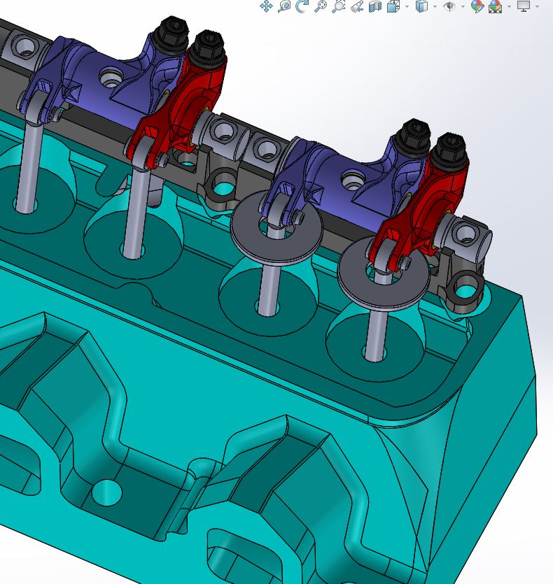
Anyway, shortly after the dyno session I got busy redesigning the rocker arms in 4140 steel, which is an alloy used in many other steel rockers, and is regularly poured by the investment casting company. In the dyno thread there were some examples of steel rocker arms posted, and I studied those pretty carefully and tried to incorporate some of the design features into the new rockers. One decision was whether or not to cant the adjuster on the intake rocker to line up with the intake pushrod angle, and after some consideration that seemed like the best approach. There will be an additional machining fixture required, and two more steps to the machining process in order to do this, but it seemed like it would be worth it from a valvetrain stability standpoint. After a week or so of design work, I had first pass designs for the intake and exhaust rocker completed, similar to the ones shown in the CAD picture below:
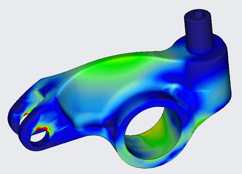
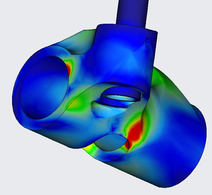
My pal Bill Conley took the first iteration of the designs and ran them through his FEA program, to see where they were stressed with 1000 pounds of valve spring pressure. Bill's help has been crucial to this effort, and right away he thought the designs had promise, but could use a little tweaking. I would not have known where to add material or how to analyze these designs without Bill's help. We went back and forth on this a few times, where I made modifications to the file and Bill analyzed them, and we finally had an intake and exhaust rocker design that looked solid. The pictures below are from Bill's FEA software program, showing areas of stress in the rocker arms with the aforementioned valvespring pressure. Red areas are to be avoided if possible, but Bill thought that based on his experience the red areas on these plots would not be a cause for concern.
Exhaust Rocker:
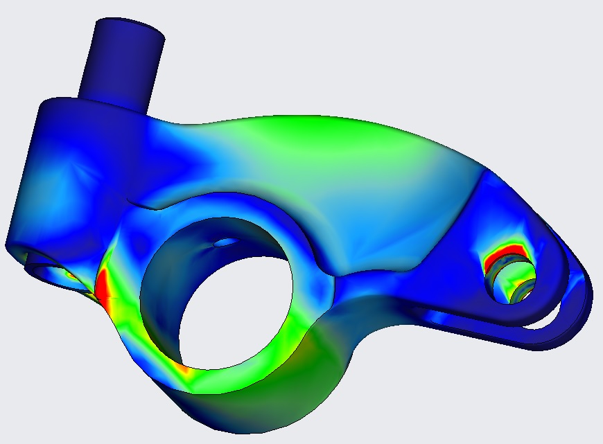
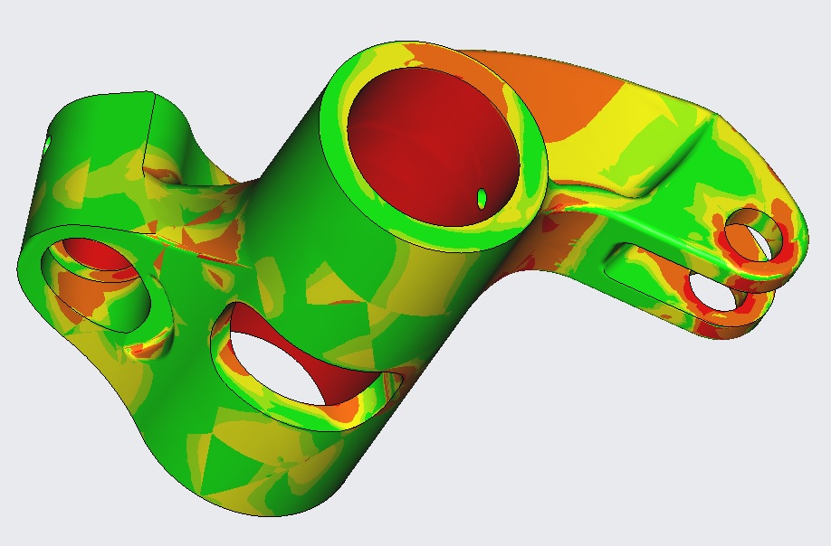
Intake Rocker:
The areas in red were not where I was seeing failures on the aluminum rockers on the dyno, so it seemed like I could proceed with these designs. One concern about the steel rockers was weight of course, but these designs turned out to be nearly as good as the aluminum rockers. Moment of inertia is a measurement of how a body resists acceleration forces, and is the key metric for achieving a lightweight valve train. According to the FEA analysis, the exhaust rocker has a moment of inertia only 8% higher than the aluminum version, which is not much of a difference. The intake rocker is even better, at only 1.5% higher; basically it is so close as to be the basically the same as the aluminum version.
With the data and analysis complete, I ordered a set of prototype rockers from the investment casting company. Unfortunately they are 4-6 weeks out, so it won't be until late October before I get them. Then they have to be machined and assembled before I can run the engine again, so now it is looking like early November before I have the next dyno results.
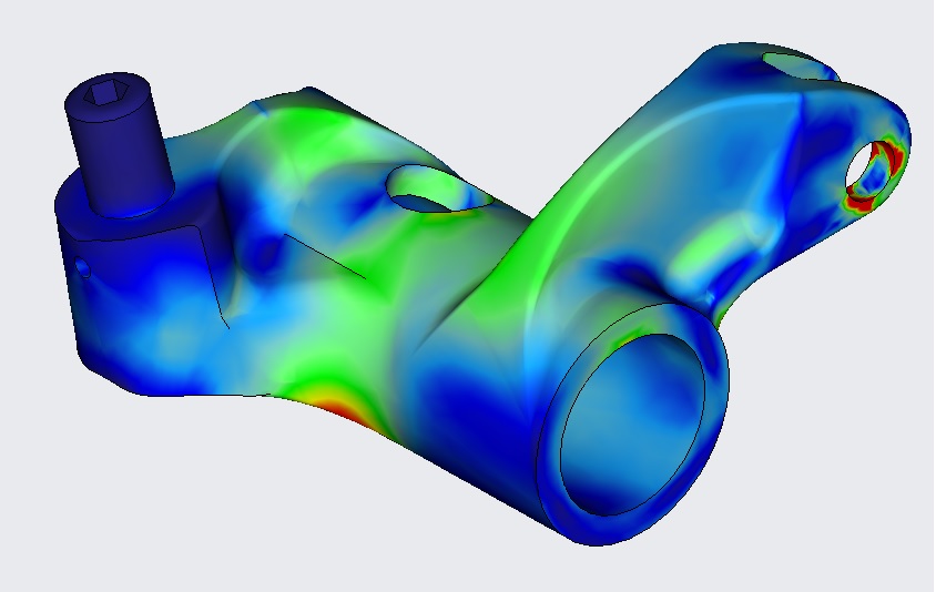
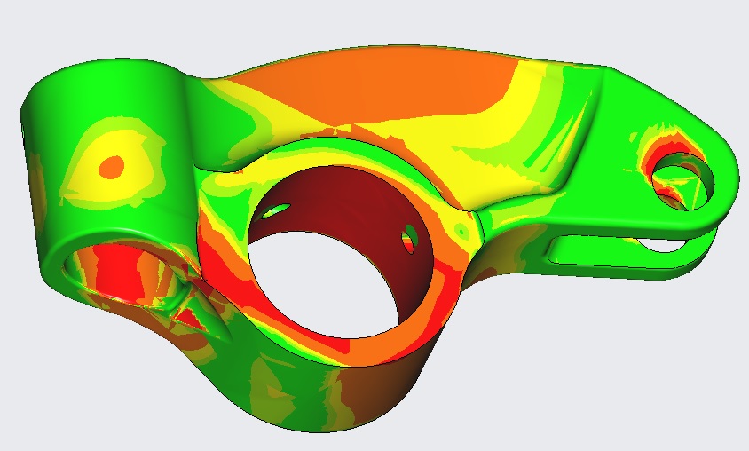
In the meantime Bill and I got to talking about fatigue life of the steel rockers; I was curious about what could be expected there, so Bill ran yet another analysis to figure this out. In the charts below the different colors relate to a baseline of 50 million cycles. Orange is exactly 50 million cycles before the onset of fatigue issues, yellow and green are more cycles, and red is less. Again based on Bill's experience the red areas are not a major concern.
Exhaust Rocker:

Intake Rocker:
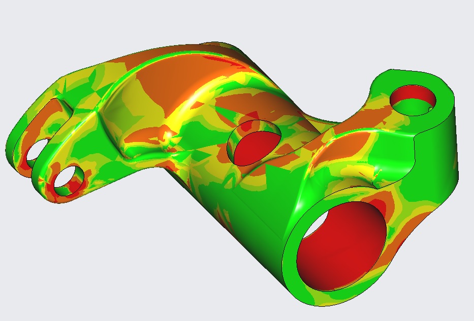
This analysis again assumed a 1000 pound valve spring when the valve is fully open. The 50 million cycle number should go way up with lower valve springs pressures, like 800 or 600. So based on this I'm feeling pretty confident about this design. The dyno testing will tell for sure, at least in the short term.
The only downside to all this is the further delay while the rockers are manufactured before I can resume testing. But I spent my professional career in product development, and it always seems to go like this, especially on complex projects. Hopefully next time around the engine will hold together like it's supposed to and we'll get some really good data.


