Author Topic: Update on the FE Power Cylinder Head Testing  (Read 19702 times)

0 Members and 1 Guest are viewing this topic.

jayb

  • Administrator
  • Hero Member
  • *****
  • Posts: 7405
    • View Profile
    • FE Power
Update on the FE Power Cylinder Head Testing
« on: September 02, 2020, 12:57:15 PM »
As time has permitted over the last couple of weeks I've been getting some dyno time in on my cylinder head package.  I have some dyno results, which at this point are not quite as good as I was hoping for, but close.  I think I've identified the horsepower issues and am working to get those fixed.  I have also found a valvetrain issue, which is in the process of being corrected, but the valvetrain issue caused a bent valve, so I need to get that fixed before I can continue testing.  The good news is that the heads appear to be solid, with no issues that I can see at this point.  The intake manifolds need some development work, which I'm hoping won't take too long; I'd like to be back testing on the dyno in 3-4 weeks.

I apologize in advance for this very long post, but I wanted to get this documented while it was still fresh in my mind.  Lots of things have been happening on this project over the last couple weeks.

Here are some details on the dyno mule, which is a 511" engine:
 - Pond block, 4.310" bore
 - RPM forged crank, 4.375" stroke
 - Crower billet rods, 6.700"
 - CP Pistons, with .039" steel top ring, .039" Napier second ring, 11 lb 3mm oil ring, 13.0:1 static compression.
 - Milodon 8 quart pan and pickup
 - Moroso windage tray
 - Precision Oil Pumps high volume pump
 - Bullet solid roller cam, 285/292 @ .050", 0.880" gross valve lift
 - FE Power RE (Raised Exhaust) heads, 2.300" intakes, 1.675" exhausts, unported
 - PAC 1356 springs set up with 340 pounds on the seat and about 1000 pounds over the nose
 - FE Power intake adapter for the cylinder heads, port matched to the intake and the heads
 - FE Power 4V or 8V intake, unported
 - FE Power rocker arm system
 - Smith Brothers 7/16" pushrods, with 0.040" restrictors built in
 - FE Power valve covers, first the clear top version, then the standard pentroof version after initial warm up
 - GZ Motorsports vacuum pump
 - DIY Autotune EFI system, used for ignition only at this point.  Crank trigger, cam sensor, and individual coil packs.


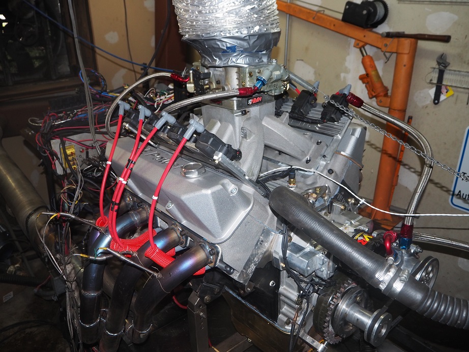
Here's what the engine looked like during most of the dyno testing:


So far I have only tested the RE version of the cylinder heads.  Most of the testing has been done with the 4V intake manifold, but I did make a few pulls with the 8V intake also.  I was hoping for 850 HP out of the 4V intake and Dominator carb, and 900 HP out of the 8V intake and two 850 carbs.  Testing has been interrupted numerous times with valve train problems, which I will try to describe in detail below.  For now, this was the only pull to 7000 RPM with the 4V intake and Dominator carb:
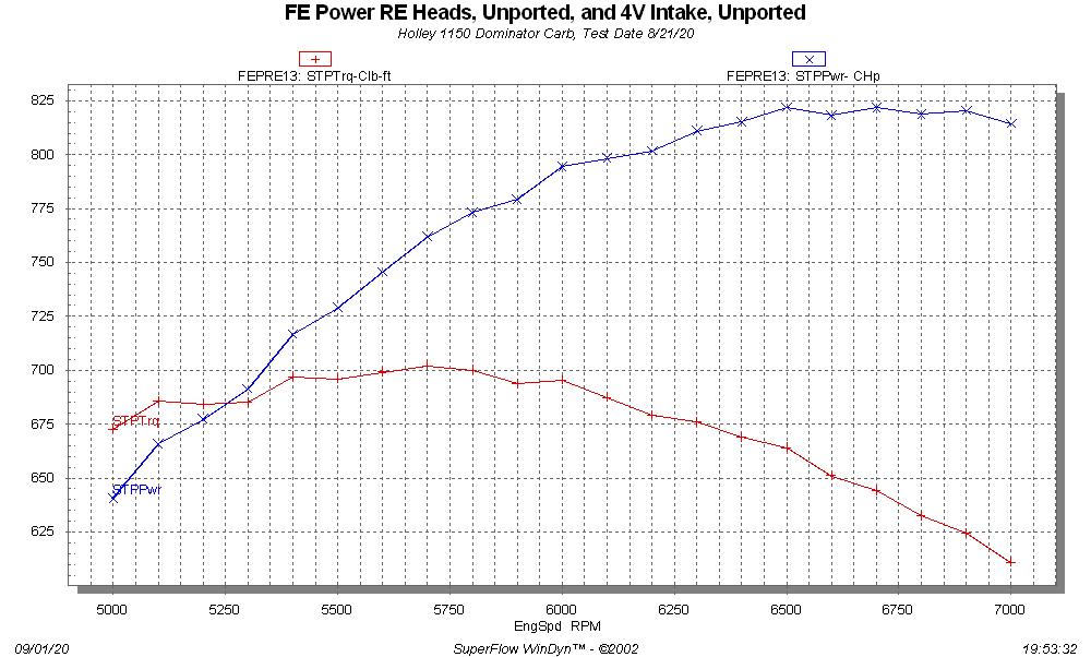


I guess 820 HP isn't too bad as a starting point.  One notable thing about this dyno pull was that the manifold vacuum at 7000 RPM was 2 inches; that's a whole lot, and indicated that the carb could be too small.  But that turned out not to be the case, from some later test results.

Backing up, I got the engine on the dyno in the middle of August, built the headers, and double and triple checked everything before starting to test.  Starting it up was a real thrill; every cast aluminum part, and almost all the billet parts on this engine, started life on my computer screen.  It was great to see all that work suddenly running an engine.  I started it with the clear top valve covers so that I could watch the oil flow in the valvetrain area, and it looked just fine.  Warm up was uneventful, and after running for about 15 minutes I shut the engine down to lash the valves, then installed the regular valve covers, which seal better when using the vacuum pump.

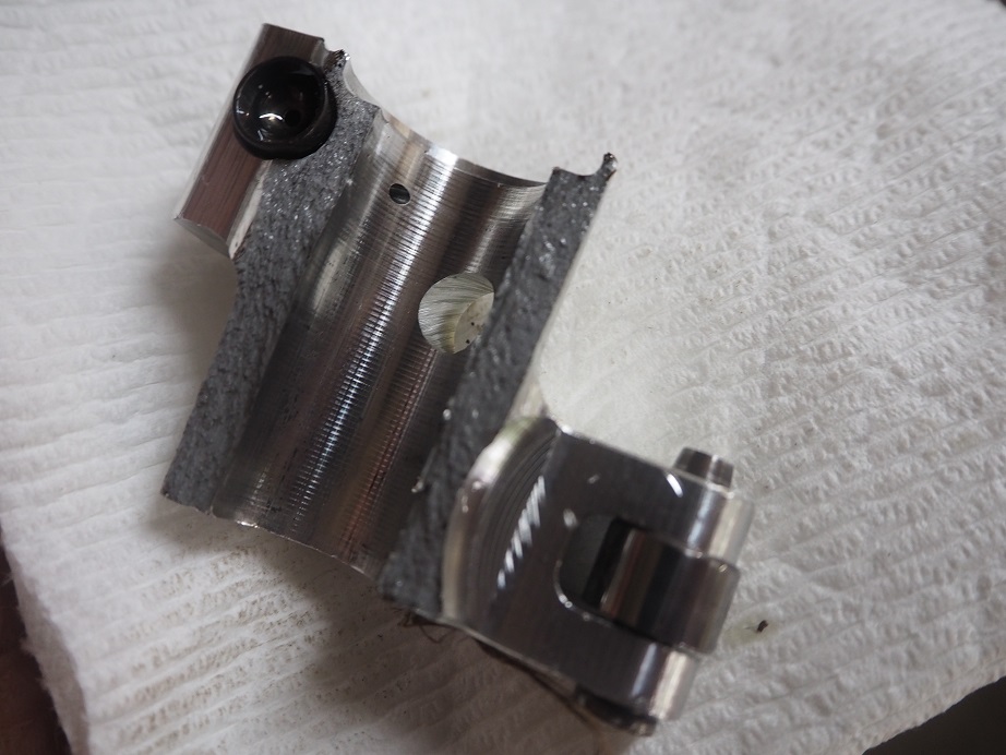
The next day Royce B came by to help with the testing.  Kevin R was also there, and a few others.  We started with a cruise test just to see how the air/fuel looked under load, and it seemed at the lower engine speeds it was OK, so we ran a dyno pull from 3000 to 4500, changed jets, ran from 3000 to 5000, jetted up again, and with the A/F looking good we started running higher.  But, at the start of one of the pulls, while the engine was still warming up, we heard a noise that sounded like a bolt had dropped into the sheet metal pan on the dyno, under the engine.  We went out and looked, but didn't see anything.  On the next pull, we were down 75 horsepower from where we had been.  I pulled the valve covers and discovered this broken intake rocker:


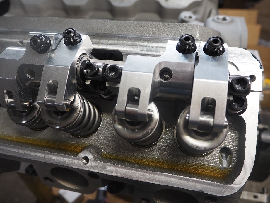
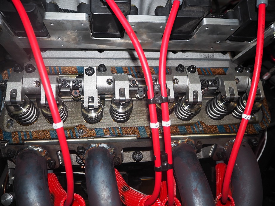
Just for reference, here are a couple of pictures of the intact valvetrain:
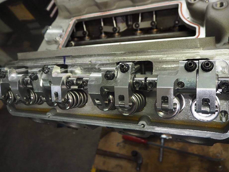


With the big valvesprings there are a lot of torsional stresses on that intake rocker.  Bill Conley had helped me with an FEA analysis of the design, and it appeared that the design would hold, but it seemed that we were looking at a fatigue failure, rather than a strength issue.  Looking at the broken rocker, you can see it is pretty thin over by the adjuster.  Larry Tores at T&D Machine had mentioned to me at the PRI show last year that most fatigue failures start right in this area, so I figured that's what was happening. 

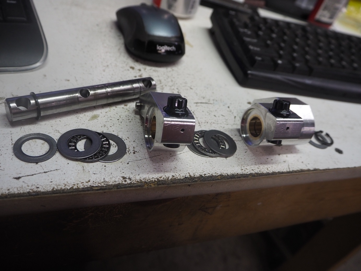
The reason that the rocker is thin there is that it is counterbored in that area for a thrust bearing.  During the FEA analysis it became clear that the side loads on the intake rocker were going to be pretty large, due to the angled pushrod. So, I designed the intake rocker with a thrust bearing that bears against the exhaust rocker, and of course since the force is transmitted through the exhaust rocker, it needs a thrust bearing on the other side too.  Here's a picture of a rocker pair assembly taken apart, showing the thrust bearings and the steel washers they ride against:


Well, it was possible that this was just a bad rocker, and I had a few spares, so we replaced that one and continued running.  We had no further issues for the remaining dyno tests, and made the one pull from 5000 to 7000 RPM.  I was very happy that the valvetrain seemed to hold together with no problem up to that engine speed.  But it was, and still is, a mystery to me why the engine peaked in power at about 6500 RPM.  I've got to believe that the cam wants to go higher than that. 

Next, we pulled off the 4V intake and 1150 Dominator, and installed the 8V intake and two 850 center squirter carbs.  I had really high hopes for this one, but unfortunately our testing was cut short by more rocker arm problems.  The first pull with the 8V intake, and really the only good pull, was 3000 to 5000 RPM.  The motor was pig rich, even showing some A/F numbers in the 9s, which you never see.  Nevertheless, it still showed a lot of promise.  The graph below shows the best 3000-5000 RPM pull with the 4V intake, and the first pull with the 8V intake:
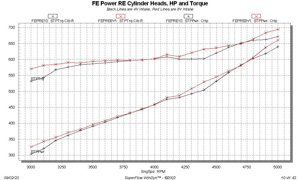


At 5000 RPM, despite being very rich, the 8V intake looks to be pulling away from the 4V intake, up by 20 HP to 660 HP at that point.  But that was as good as it got.  We jetted down, and for some unknown reason, A/F started looking better but power was down substantially.  We tried another pull, and then the motor just didn't sound right.  Pulled the valve covers, and found two more broken intake rockers.  Crap  >:(  Done for the day.

The conclusions from the first round of testing were twofold:  The intake rocker needed to be redesigned to add material around the adjuster, and the 4V intake needed to be tested with a bigger carb, to try to reduce vacuum at wide open throttle.  On the intake rocker, I didn't have room to move the adjuster towards the thicker side, because then the pushrod would hit the intake adapter.  But the exhaust rocker was thicker on both sides of the adjuster than the intake rocker was on it's thin side, and since the pushrod comes straight up for the exhaust rocker, it wouldn't be subject to the kind of torsional stresses that the intake rocker was.  So, I moved the counterbore that had been in the intake rocker over to the exhaust rocker, to leave the intake rocker as thick as possible around the adjuster. 

For the next few days I revised my CNC programming for the rocker arms and machined a new set of intake rockers, and modified the existing set of exhaust rockers.  Along the way, Royce talked to Jon Kaase about the issues we were seeing (Royce knows Jon from his Engine Masters engines, and I've met Jon at the PRI show).  Jon steered Royce to a guy who makes Kaase's top end rockers, and there was an online article about his parts.  One of the things I found interesting in his article was that he shot peens his aluminum rocker arms.  I thought this might be a good thing for me to do also, because machining aluminum creates tensile stresses on the outside of the material, and can lead to fatigue problems.  Shot peening changes those to compressive stresses, which are more resistant to fatigue.  I found a local company who could shot peen my rockers, so I dropped them off for the work.  They were able to get it done in a couple days, and I got them back last Friday.  Here's a couple pictures of the shot peened rockers:
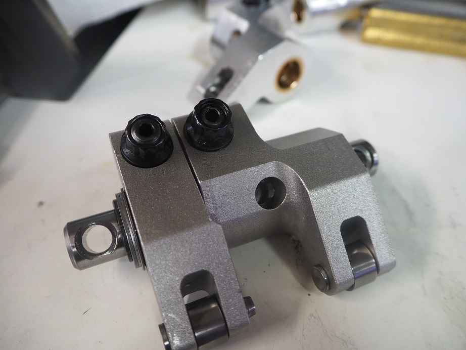


In the meantime, Royce had found a guy with one of those billet body 1400 cfm Dominator carbs, who was willing to lend it to us for testing.  He brought it up last Friday, but it took most of the afternoon to re-assemble the valvetrain.  Installing it, we encountered a strange problem with the rockers; even with the adjusters backed all the way off, there was no lash.  I found out later that shot peening can deform aluminum, and the shot peening operation had actually changed the dimensions of the rockers, leading to the problem.  I shimmed up the stands to get some lash, but then when the rockers started getting cycled with the engine running, the lash started backing out; apparently the rockers were relaxing into the original machined shape.  I won't go into all the details, but this led to some weird noises from the valvetrain, that we finally figured out were broken adjusters; continually adjusting the lash had left them sticking too far out of the rocker arms. 

Finally by Saturday afternoon we had this all ironed out, engine was running fine, no more lash issues, etc., and were ready to make a pull with the 4V intake and the big Dominator carb.  But I think we only made one pull, when Royce noticed some smoke coming out of the vacuum pump catch can when the engine was running.  We pulled the valve covers again, and on the left side I noticed that we had water in the oil.  Ugh  :(

So, one of the nightmare scenarios with these heads was that they wouldn't hold up to punishment under running conditions, despite the thick walls I had put into the casting design.  However, the problem turned out to be the intake gasket, which was leaking water at the rear water opening of the right head.  Sunday I pressurized the cooling system to find the leak, and then pulled the intake adapter off.  When I looked at it in detail it became plain that I had machined the intake adapter incorrectly, and not left enough material to completely cover the gasket over the hole in the rear of the head.  If I had installed the intake adapter without a gasket, I'd have seen about a .040" slot of the rear water opening in the head exposed.  The gasket held there for a while, but finally gave up on Saturday afternoon.  Another simple issue, that will be easy to fix with a correction to the machining program, but it stopped us in our tracks on Saturday.

By the end of the day Monday I had made up some thin brass plates to block off the rear water jacket holes in the heads, and re-installed the intake adapter and valvetrain.  Tuesday I ran the engine again, with the 4V intake and the big carb, but encountered another problem with the #8 exhaust rocker.  During operation, it was jamming the adjuster back into the body of the rocker arm, opening the lash way up.  #8 had been one of the cylinders where one of the intake rockers had failed during a pull, and I'd been wondering if I'd done some damage in one of those cylinders. This morning I fabricated a tool to remove the valve springs with the heads on the engine, and did a leakdown check on #8, and sure enough the exhaust valve is bent.  I'm thinking the bent valve contacted the piston and jammed the adjuster up into the rocker arm.

I did get some good data up to 6000 RPM with the big carb, and much to my surprise, the engine was pulling the same amount of vacuum that the 1150 Dominator was at the same speeds.  I don't think there's any way that carb is too small, so now I'm suspecting the 4V intake manifold is a restriction, and probably limiting power production.  I've been talking to Joe Craine, and he has agreed to flow both the 4V and 8V intakes, on the intake adapter, and make some modifications to improve them.  Anyone who has been following this project probably remembers that my first go around with the RE heads showed exhaust flow that was not that great; I sent part of a head down to Joe and he modified the port to work better.  Then I took the modifications and incorporated them into the casting patterns, and the exhaust ports as cast picked up about 40 cfm.  I'm hoping that Joe can find some improvements in the intake manifolds, that I can also incorporate into revised castings.

I remain surprised by the relatively low RPM where this engine wants to peak in power.  I supposed it could be related to the intakes, but with a 285/292 @ .050 cam, I was figuring it would peak well over 7000 RPM.  I suppose it could be intake related, so we'll find out if that's the case when I dyno again with Joe's improvements.

Also, I've been thinking that I need to go to steel rocker arms on this setup.  Even though I haven't broken any more intake rockers since the design change, I've lost some confidence in them as a result, and would like a more bulletproof part.  I think while I am waiting for valves, and for Joe to flow the intakes, I will work on getting a revised design for a steel rocker arm finished and machined.  I'm also looking at an investment casting option for the steel rockers.

I will be back on the dyno with this engine as soon as possible, hopefully by the end of the month.  I'm not sure if I've fleshed out all the problems yet, but I've certainly identified the most obvious ones, so next time around the testing should go quite a bit smoother. 
« Last Edit: September 02, 2020, 02:30:52 PM by jayb »
Jay Brown
- 1969 Mach 1, Drag Week 2005 Winner NA/BB, 511" FE (10.60s @ 129); Drag Week 2007 Runner-Up PA/BB, 490" Supercharged FE (9.35 @ 151)
- 1964 Ford Galaxie, Drag Week 2009 Winner Modified NA (9.50s @ 143), 585" SOHC
- 1969 Shelby Clone, Drag Week 2015 Winner Modified NA (Average 8.98 @ 149), 585" SOHC


blykins

  • Hero Member
  • *****
  • Posts: 4822
    • View Profile
    • Lykins Motorsports
Re: Update on the FE Power Cylinder Head Testing
« Reply #1 on: September 02, 2020, 01:17:11 PM »
Many props to you, Jay.

First of all, you've put in a ton of design work and it will all come to fruition on a solid combination.

Second of all, thank you for just laying it all out, even the cons with the pros. 

Brent Lykins
Lykins Motorsports
Custom FE Street, Drag Race, Road Race, and Pulling Truck Engines
Custom Roller & Flat Tappet Camshafts
www.lykinsmotorsports.com
brent@lykinsmotorsports.com
www.customfordcams.com
502-759-1431
Instagram:  brentlykinsmotorsports
YouTube:  Lykins Motorsports

Rory428

  • Hero Member
  • *****
  • Posts: 1006
    • View Profile
Re: Update on the FE Power Cylinder Head Testing
« Reply #2 on: September 02, 2020, 01:34:45 PM »
Interesting read, Jay, I guess with trail blazing some teething pains are to be expected, but it must be really satisfying to see your ideas actually running on an actual engine. I assume the large hole on the top of the offset rockers is for access to the shaft bolts? It does seen strange that the RPM peak is so low, that certainly is not a RV cam! Thanks for posting this, a lot of us are living vicariously thru your adventures.
1978 Fairmont,FE 427 with 428 crank, 4 speed Jerico best of 9.972@132.54MPH 1.29 60 foot
1985 Mustang HB 331 SB Ford, 4 speed Jerico, best of 10.29@128 MPH 1.40 60 foot.
1974 F350 race car hauler 390 NP435 4 speed
1959 Ford Meteor 2 dr sedan. 428 Cobra Jet, 4 speed Toploader. 12.54@ 108 MPH

fryedaddy

  • Hero Member
  • *****
  • Posts: 1252
    • View Profile
Re: Update on the FE Power Cylinder Head Testing
« Reply #3 on: September 02, 2020, 01:40:33 PM »
are you planning to test the other head with stock exhaust position any time soon?
1966 comet caliente 428 4 speed owned since 1983                                                 1973 f250 ranger xlt 360 4 speed papaw bought new

HarleyJack17

  • Sr. Member
  • ****
  • Posts: 271
    • View Profile
Re: Update on the FE Power Cylinder Head Testing
« Reply #4 on: September 02, 2020, 01:42:50 PM »
Interesting info and some really nice work! I am not an engineer by trade, but my first thought on seeing the rocker issue was steel would help.  Definitely asking a lot from it and I have seen iterations similar to what you have in steel, but not quite under the same loads. She will be heavy on the intake side, but I think it very well could be the answer to correcting what looks to be a pattern.  Very surprising on the vacuum side/intake info.  I have a feeling that once you get the gremlins happy you are going to be more than surprised.  Keep up the good work and take the challenges in stride!

e philpott

  • Hero Member
  • *****
  • Posts: 923
    • View Profile
Re: Update on the FE Power Cylinder Head Testing
« Reply #5 on: September 02, 2020, 02:13:22 PM »
You actually have had less problems than I thought you would for being a all new designed top end up . for a first pull I think you did real good as it's hard to thrash anything with rocker trouble going on , congrats .


Joe-JDC

  • Hero Member
  • *****
  • Posts: 1490
  • Truth stands on its own merit.
    • View Profile
Re: Update on the FE Power Cylinder Head Testing
« Reply #6 on: September 02, 2020, 02:14:38 PM »
Very cool indeed!  Just wondering if that middle bolt on the rocker assembly shaft is actually necessary?  If not, would that give the added strength necessary to keep an aluminum rocker arm?  Joe-JDC
Joe-JDC '70GT-500

frnkeore

  • Hero Member
  • *****
  • Posts: 1135
    • View Profile
Re: Update on the FE Power Cylinder Head Testing
« Reply #7 on: September 02, 2020, 02:17:23 PM »
Some food for thought, regarding the rockers. I assume the material is 7075?

Widen the adjuster side, 30% and use a larger radius.

Do you really need Torrington thrust bearings? Could you use hardened washers in the c'bored Ex rockers? Gaining strength at the adjuster. Also, narrow the In side of the Ex rocker, a little more and widen the In rocker.

Another thing, that could be a great help is, rough machine the IN rockers and then finish machine after re-heat treat. They will be stronger, overall and more stable, if the oil temp, doesn't effect the HT. Check with a HTer to see what the highest temp, you want them to used at, will do to them.
« Last Edit: September 02, 2020, 02:23:05 PM by frnkeore »
Frank

Gaugster

  • Sr. Member
  • ****
  • Posts: 396
    • View Profile
Re: Update on the FE Power Cylinder Head Testing
« Reply #8 on: September 02, 2020, 02:31:31 PM »
Issues crop up. It's part of the development process and the lessons learned are priceless. I imagine with a new combustion chamber that setting the timing curve and other ignition items are very much an unknown at this stage. May be contributing to the higher rpm performance. Bigger fish to fry though. Thanks for the update!!!!
« Last Edit: September 02, 2020, 02:37:55 PM by Gaugster »
John - '68 Cougar XR7 390 FE (X-Code) 6R80 AUTO

jayb

  • Administrator
  • Hero Member
  • *****
  • Posts: 7405
    • View Profile
    • FE Power
Re: Update on the FE Power Cylinder Head Testing
« Reply #9 on: September 02, 2020, 02:34:55 PM »
Very cool indeed!  Just wondering if that middle bolt on the rocker assembly shaft is actually necessary?  If not, would that give the added strength necessary to keep an aluminum rocker arm?  Joe-JDC

Without the middle bolt the tool steel rocker shaft flexes up .005" with 1000 pounds of valve spring pressure, according to the FEA analysis.  I thought that was too much, so the middle bolt was used.  FEA results were much better that way.  I also noticed that the T&D rockers that use individual pairs use a bolt between the rockers, and of course so does the stock FE setup.  I just feel more comfortable with it in there...
Jay Brown
- 1969 Mach 1, Drag Week 2005 Winner NA/BB, 511" FE (10.60s @ 129); Drag Week 2007 Runner-Up PA/BB, 490" Supercharged FE (9.35 @ 151)
- 1964 Ford Galaxie, Drag Week 2009 Winner Modified NA (9.50s @ 143), 585" SOHC
- 1969 Shelby Clone, Drag Week 2015 Winner Modified NA (Average 8.98 @ 149), 585" SOHC


jayb

  • Administrator
  • Hero Member
  • *****
  • Posts: 7405
    • View Profile
    • FE Power
Re: Update on the FE Power Cylinder Head Testing
« Reply #10 on: September 02, 2020, 02:39:20 PM »
Some food for thought, regarding the rockers. I assume the material is 7075?

Widen the adjuster side, 30% and use a larger radius.

Do you really need Torrington thrust bearings? Could you use hardened washers in the c'bored Ex rockers? Gaining strength at the adjuster. Also, narrow the In side of the Ex rocker, a little more and widen the In rocker.

Another thing, that could be a great help is, rough machine the IN rockers and then finish machine after re-heat treat. They will be stronger, overall and more stable, if the oil temp, doesn't effect the HT. Check with a HTer to see what the highest temp, you want them to used at, will do to them.

Yes, it is 7075.  There is no room to widen the intake rocker on the thin side, so that is not an option.  Also, with the angled pushrods, side load on the intake rocker approaches 300 pounds at 1000 pounds open, so I think the thrust bearings are necessary.  It may be that I could get by without one on the exhaust side, because the exhaust is closing as the intake is opening, and peak side load doesn't occur until peak intake lift.  But the exhaust rockers are not the problem, the intake rockers are.

I think a steel rocker arm is going to be the way to go...

Jay Brown
- 1969 Mach 1, Drag Week 2005 Winner NA/BB, 511" FE (10.60s @ 129); Drag Week 2007 Runner-Up PA/BB, 490" Supercharged FE (9.35 @ 151)
- 1964 Ford Galaxie, Drag Week 2009 Winner Modified NA (9.50s @ 143), 585" SOHC
- 1969 Shelby Clone, Drag Week 2015 Winner Modified NA (Average 8.98 @ 149), 585" SOHC


jayb

  • Administrator
  • Hero Member
  • *****
  • Posts: 7405
    • View Profile
    • FE Power
Re: Update on the FE Power Cylinder Head Testing
« Reply #11 on: September 02, 2020, 02:42:32 PM »
Issues crop up. It's part of the development process and the lessons learned are priceless. I imagine with a new combustion chamber that setting the timing curve and other ignition items are very much an unknown at this stage. May be contributing to the higher rpm performance. Bigger fish to fry though. Thanks for the update!!!!

I forgot to put that in the post, it wanted 33 total at most.  Not much drop-off at 32, but power was down noticeably at 30.
Jay Brown
- 1969 Mach 1, Drag Week 2005 Winner NA/BB, 511" FE (10.60s @ 129); Drag Week 2007 Runner-Up PA/BB, 490" Supercharged FE (9.35 @ 151)
- 1964 Ford Galaxie, Drag Week 2009 Winner Modified NA (9.50s @ 143), 585" SOHC
- 1969 Shelby Clone, Drag Week 2015 Winner Modified NA (Average 8.98 @ 149), 585" SOHC


Gaugster

  • Sr. Member
  • ****
  • Posts: 396
    • View Profile
Re: Update on the FE Power Cylinder Head Testing
« Reply #12 on: September 02, 2020, 02:51:58 PM »
Issues crop up. It's part of the development process and the lessons learned are priceless. I imagine with a new combustion chamber that setting the timing curve and other ignition items are very much an unknown at this stage. May be contributing to the higher rpm performance. Bigger fish to fry though. Thanks for the update!!!!

I forgot to put that in the post, it wanted 33 total at most.  Not much drop-off at 32, but power was down noticeably at 30.
I should have known giving your tendency for being thorough. Looking forward to more progress. Those rubber chickens need to make an appearance during your next photo shoot.
John - '68 Cougar XR7 390 FE (X-Code) 6R80 AUTO

turbohunter

  • Hero Member
  • *****
  • Posts: 2509
    • View Profile
Re: Update on the FE Power Cylinder Head Testing
« Reply #13 on: September 02, 2020, 02:58:13 PM »
1000 lbs open. Holy crap.
Seriously, all this stuff you’ll work out. I second Brent saying thanks for giving us the whole story. Not just the hero stuff.
Takes big brass balls Jay.
« Last Edit: September 02, 2020, 03:01:01 PM by turbohunter »
Marc
'61 F100 292Y
'66 Mustang Injected 428
'66 Q code Country Squire wagon


jayb

  • Administrator
  • Hero Member
  • *****
  • Posts: 7405
    • View Profile
    • FE Power
Re: Update on the FE Power Cylinder Head Testing
« Reply #14 on: September 02, 2020, 03:18:51 PM »
I actually overkilled the valve spring pressure on purpose, to try to find any weak spots in the valvetrain.  I succeeded LOL  :o
Jay Brown
- 1969 Mach 1, Drag Week 2005 Winner NA/BB, 511" FE (10.60s @ 129); Drag Week 2007 Runner-Up PA/BB, 490" Supercharged FE (9.35 @ 151)
- 1964 Ford Galaxie, Drag Week 2009 Winner Modified NA (9.50s @ 143), 585" SOHC
- 1969 Shelby Clone, Drag Week 2015 Winner Modified NA (Average 8.98 @ 149), 585" SOHC


My427stang

  • Hero Member
  • *****
  • Posts: 3929
    • View Profile
Re: Update on the FE Power Cylinder Head Testing
« Reply #15 on: September 02, 2020, 03:23:10 PM »
I actually overkilled the valve spring pressure on purpose, to try to find any weak spots in the valvetrain.  I succeeded LOL  :o

That’s pretty funny. What is the advertised duration on that one?
---------------------------------
Ross
Bullock's Power Service, LLC
- 70 Fastback Mustang, 489 cid FE, Victor, SEFI, Erson SFT cam, TKO-600 5 speed, 4.11 9 inch.
- 71 F100 shortbed 4x4, 461 cid FE, headers, Victor Pro-flo EFI, Comp Custom HFT cam, 3.50 9 inch

jayb

  • Administrator
  • Hero Member
  • *****
  • Posts: 7405
    • View Profile
    • FE Power
Re: Update on the FE Power Cylinder Head Testing
« Reply #16 on: September 02, 2020, 03:38:10 PM »
Advertised is 319/334.
Jay Brown
- 1969 Mach 1, Drag Week 2005 Winner NA/BB, 511" FE (10.60s @ 129); Drag Week 2007 Runner-Up PA/BB, 490" Supercharged FE (9.35 @ 151)
- 1964 Ford Galaxie, Drag Week 2009 Winner Modified NA (9.50s @ 143), 585" SOHC
- 1969 Shelby Clone, Drag Week 2015 Winner Modified NA (Average 8.98 @ 149), 585" SOHC


Joey120373

  • Sr. Member
  • ****
  • Posts: 372
    • View Profile
Re: Update on the FE Power Cylinder Head Testing
« Reply #17 on: September 02, 2020, 03:42:44 PM »
Wow, I know you were hoping for more power, but, 820 at 6500 on the first set of pulls is pretty darned impressive I think. I notice the power past that seems to be a bit of a sine wave.

I’m guessing once you get the manifold vacuum down to a reasonable level, that will clean up.

C6AE

  • Full Member
  • ***
  • Posts: 167
    • View Profile
Re: Update on the FE Power Cylinder Head Testing
« Reply #18 on: September 02, 2020, 05:00:52 PM »
Investment cast rockers will allow a redesign on a lot of the shapes, paring off some weight where not not needed.
I like it!

My427stang

  • Hero Member
  • *****
  • Posts: 3929
    • View Profile
Re: Update on the FE Power Cylinder Head Testing
« Reply #19 on: September 02, 2020, 05:05:31 PM »
Jay, in the end, you likely asked too much of the rockers.  Once you get that sorted you can get some clean pulls

Some other thoughts, the additional spring pressure, certainly reasonable thought for future use (or misuse), certainly added to deflection and may not have even helped.  So you may find a more "normal" ....funny saying that with this engine....spring pressure could be not only easier on parts but also make more power

I also think there is more to be gained in cam choice, but son of a gun, that's a successful run, take pride in what you did.  I would think that OEM heads aren't that successful first time at bat
---------------------------------
Ross
Bullock's Power Service, LLC
- 70 Fastback Mustang, 489 cid FE, Victor, SEFI, Erson SFT cam, TKO-600 5 speed, 4.11 9 inch.
- 71 F100 shortbed 4x4, 461 cid FE, headers, Victor Pro-flo EFI, Comp Custom HFT cam, 3.50 9 inch

70tp

  • Full Member
  • ***
  • Posts: 101
    • View Profile
Re: Update on the FE Power Cylinder Head Testing
« Reply #20 on: September 02, 2020, 05:08:46 PM »
Awesome Jay!!   The bright side of this is now you can , with the head off, see what the burn pattern is in the chamber and top of pistons.   Also any clean, washed areas.  Maybe some rocker problems could be an unfriendly lobe shape that is putting some harmonics into the valve train?  Not necessarily valve float but something happening below valve float rpm?     

machoneman

  • Hero Member
  • *****
  • Posts: 3853
    • View Profile
Re: Update on the FE Power Cylinder Head Testing
« Reply #21 on: September 02, 2020, 05:46:01 PM »
Definitely steel.  ;) Aluminum may work for a drag engine but for any longevity, I think your decision for a steel rocker is the correct solution.
Bob Maag

Hemi Joel

  • Sr. Member
  • ****
  • Posts: 497
    • View Profile
Re: Update on the FE Power Cylinder Head Testing
« Reply #22 on: September 02, 2020, 06:31:51 PM »
Dear Jay,

It is amazing what you have accomplished. Even though you are not finished with your R&D yet, I consider your project a smashing success. Congratulations!

Very truly yours,

One of the Others

ntheogen

  • Sr. Member
  • ****
  • Posts: 254
    • View Profile
Re: Update on the FE Power Cylinder Head Testing
« Reply #23 on: September 02, 2020, 08:38:00 PM »
Congratulations Mr. Brown, stellar work. I'm impressed that it's gone relatively smoothly given its an all new design from scratch.

Jack

bsprowl

  • Full Member
  • ***
  • Posts: 213
    • View Profile
    • Ford FE Information
Re: Update on the FE Power Cylinder Head Testing
« Reply #24 on: September 02, 2020, 09:00:54 PM »
Thank you for sharing the details.  Something always pops up in testing.  That's why its called testing.   Power is more than meets my expectations for the small amount of tuning you were able to do.  The final results should be great.

Thanks again

Bob

WerbyFord

  • Sr. Member
  • ****
  • Posts: 335
    • View Profile
Re: Update on the FE Power Cylinder Head Testing
« Reply #25 on: September 02, 2020, 11:23:11 PM »
Definitely steel.  ;) Aluminum may work for a drag engine but for any longevity, I think your decision for a steel rocker is the correct solution.
x2 on steel.
IIRC, steel has a flat fatigue limit when loaded properly (under half its static strength).
Loaded below that, it will cycle forever, it just doesn't care.

Aluminum (and austenitic stainless, copper, etc) has NO fatigue limit - if loaded substantially, it will keep fatiguing until it breaks, as Boeing found out when those 737s became convertibles on the way to Hawaii.

SUCH an awesome engine.
Did I miss the head flows somewhere, and the header dimensions?
Open headers I assume?
There aren't enough mufflers in the USA to let that thing flow.

Will be interested to see JDC flow those intakes, the Gonkulator will want that info.

I do not envy Bill Conley doing that FEA. Complicated geometry. I started doing FEA in 1982 but something that complex, and dynamic fatigue failure - complicated.

WConley

  • Hero Member
  • *****
  • Posts: 1160
  • No longer walking funny!
    • View Profile
Re: Update on the FE Power Cylinder Head Testing
« Reply #26 on: September 03, 2020, 01:21:11 AM »
Werby - The tools have gotten really good.  The problem is that you have to know how to load / constrain the model and interpret the results.  That's where the experience comes in...


It's a powerful thing, but like a 427 Cobra you can drive it wrong and end up in the weeds  >:( 
« Last Edit: September 03, 2020, 01:50:21 AM by WConley »
A careful study of failure will yield the ingredients for success.

cjshaker

  • Hero Member
  • *****
  • Posts: 4460
    • View Profile
Re: Update on the FE Power Cylinder Head Testing
« Reply #27 on: September 03, 2020, 07:50:52 AM »
2" of vacuum at RPM, with a huge carb, certainly seems to indicate that the heads are wanting more! Me thinks a tunnel ram is in your future!  8) You didn't mention intake vacuum with the 8 barrel intake. Was it high also? I would assume it dropped some with the 8 barrel. If not much, then it seems like the heads want more than the intakes can produce. Certainly on that 4 barrel, at least. Were the 8 barrel carbs a known variable? In other words, had they been used successfully on another 8 barrel engine? If so, there has to be a reason they were so pig rich. Vacuum alone shouldn't do that, unless, combined with airflow, it started pulling fuel from places it shouldn't have.

It looks like you have temp probes in each exhaust tube. How were the exhaust temps? That could indicate any issues with intake flow problems (reversion issues with such a big cam, or just a bottleneck?), or any coil/ignition issues, if there are any.

At the risk of sounding like a doofus for missing something obvious, how does that center shaft bolt work? Is the bottom of the intake rocker slotted so that the bolt travels through the rocker, and the rocker pivots over the top of the bolt?

On the intake rocker adjuster; Is there not enough room to move the adjuster over slightly, for additional strength, and modify/machine the intake adapter for some additional pushrod clearance? Maybe there's not enough room around the port to do that?

Okay, sorry for all the questions. Thanks for the great write-up, and it seems like you're only scratching the surface with power production. This is going to get really interesting, as I think you have some real intake development in your future.
Doug Smith


'69 R-code Mach 1, 427 MR, 2x4, Jerico, 4.30 Locker
'70 F-350 390
'55 Ford Customline 2dr
'37 Ford Coupe

428kidd

  • Sr. Member
  • ****
  • Posts: 421
    • View Profile
Re: Update on the FE Power Cylinder Head Testing
« Reply #28 on: September 03, 2020, 08:41:33 AM »
Very kool to hear Jay and congrats, looking forward to some full pulls!

jayb

  • Administrator
  • Hero Member
  • *****
  • Posts: 7405
    • View Profile
    • FE Power
Re: Update on the FE Power Cylinder Head Testing
« Reply #29 on: September 03, 2020, 11:05:19 AM »

Did I miss the head flows somewhere, and the header dimensions?
Open headers I assume?
There aren't enough mufflers in the USA to let that thing flow.

Will be interested to see JDC flow those intakes, the Gonkulator will want that info.

I do not envy Bill Conley doing that FEA. Complicated geometry. I started doing FEA in 1982 but something that complex, and dynamic fatigue failure - complicated.

Head flows are in this post:

http://fepower.net/simplemachinesforum/index.php?topic=7336.0

Headers are 2" to 2-1/8" to 2-1/4", most of them with a 6" bend radius, into merge collectors, going into the dyno's exhaust system, which has four 3" inlet and outlet turbo mufflers.
Jay Brown
- 1969 Mach 1, Drag Week 2005 Winner NA/BB, 511" FE (10.60s @ 129); Drag Week 2007 Runner-Up PA/BB, 490" Supercharged FE (9.35 @ 151)
- 1964 Ford Galaxie, Drag Week 2009 Winner Modified NA (9.50s @ 143), 585" SOHC
- 1969 Shelby Clone, Drag Week 2015 Winner Modified NA (Average 8.98 @ 149), 585" SOHC


BigBlueIron

  • Sr. Member
  • ****
  • Posts: 405
    • View Profile
Re: Update on the FE Power Cylinder Head Testing
« Reply #30 on: September 03, 2020, 11:14:01 AM »
Amazing stuff!

Rambling thoughts.. Obviously steel would immediately add an immense amount of strength and most likely be the ultimate solution but I believe you could make the aluminum work.

In moving the thrust relief to exhaust you already made a quite a strength improvement not only extending the amount of area for the pivot but just more material.  I don't see the hole for the center bolt being as critical as some. And it would take an even stronger rocker arm to withstand the movement your eliminating with the extra bolt. 

What about adding a rib horizontally along the cross sectional area from the adjuster along the body, kind of like a gusset for lack of term, this would help transfer energy over the offset and add vertical material along length of the barrel area at its weakest point. It looks like there is room for a larger radius on the valve side, maybe not. Just first thing that crossed my mind upon seeing the broken rocker. 

jayb

  • Administrator
  • Hero Member
  • *****
  • Posts: 7405
    • View Profile
    • FE Power
Re: Update on the FE Power Cylinder Head Testing
« Reply #31 on: September 03, 2020, 11:31:30 AM »
2" of vacuum at RPM, with a huge carb, certainly seems to indicate that the heads are wanting more! Me thinks a tunnel ram is in your future!  8) You didn't mention intake vacuum with the 8 barrel intake. Was it high also? I would assume it dropped some with the 8 barrel. If not much, then it seems like the heads want more than the intakes can produce. Certainly on that 4 barrel, at least. Were the 8 barrel carbs a known variable? In other words, had they been used successfully on another 8 barrel engine? If so, there has to be a reason they were so pig rich. Vacuum alone shouldn't do that, unless, combined with airflow, it started pulling fuel from places it shouldn't have.

It looks like you have temp probes in each exhaust tube. How were the exhaust temps? That could indicate any issues with intake flow problems (reversion issues with such a big cam, or just a bottleneck?), or any coil/ignition issues, if there are any.

At the risk of sounding like a doofus for missing something obvious, how does that center shaft bolt work? Is the bottom of the intake rocker slotted so that the bolt travels through the rocker, and the rocker pivots over the top of the bolt?

On the intake rocker adjuster; Is there not enough room to move the adjuster over slightly, for additional strength, and modify/machine the intake adapter for some additional pushrod clearance? Maybe there's not enough room around the port to do that?

Okay, sorry for all the questions. Thanks for the great write-up, and it seems like you're only scratching the surface with power production. This is going to get really interesting, as I think you have some real intake development in your future.

I actually didn't run the 8V at any real high engine speeds, but at the lower speeds it did look like it had a lower vacuum than the 4V intake.  The 850 center squirters had not been used before, they were a set I bought from Barry R years ago and had Drew rebuild for me.  So I was starting from scratch on the tuning with those.

Exhaust temps all tracked, but there was some variation, about 150 degrees from low to high.  However, #8 had the bent exhaust valve, and it was highest, so probably some burning was going on in that pipe.

Doug, it's all I can do to restrain myself from making a wise-ass comment about you sounding like a doofus  ;D  That center bolt in each rocker pair goes into a post in the steel bar that holds the rocker shafts, picture below.  So the top of the intake rocker has a hole for the bolt to go through when the valves are closed, and the bottom of the rocker has a slot around the post, to allow movement:


On the intake rocker adjuster, it is as far over as it can be without going into the port, while leaving 0.050" of material around the port opening at the lower corner.  In fact on a few of the pushrods I can see interference where they are just brushing the intake adapter at that lower point, so I'm pretty much out of room unless I modify the port.  I'd rather not do that, but we'll see what Joe finds with the flow testing...
Jay Brown
- 1969 Mach 1, Drag Week 2005 Winner NA/BB, 511" FE (10.60s @ 129); Drag Week 2007 Runner-Up PA/BB, 490" Supercharged FE (9.35 @ 151)
- 1964 Ford Galaxie, Drag Week 2009 Winner Modified NA (9.50s @ 143), 585" SOHC
- 1969 Shelby Clone, Drag Week 2015 Winner Modified NA (Average 8.98 @ 149), 585" SOHC


jayb

  • Administrator
  • Hero Member
  • *****
  • Posts: 7405
    • View Profile
    • FE Power
Re: Update on the FE Power Cylinder Head Testing
« Reply #32 on: September 03, 2020, 11:37:48 AM »
Amazing stuff!

Rambling thoughts.. Obviously steel would immediately add an immense amount of strength and most likely be the ultimate solution but I believe you could make the aluminum work.

In moving the thrust relief to exhaust you already made a quite a strength improvement not only extending the amount of area for the pivot but just more material.  I don't see the hole for the center bolt being as critical as some. And it would take an even stronger rocker arm to withstand the movement your eliminating with the extra bolt. 

What about adding a rib horizontally along the cross sectional area from the adjuster along the body, kind of like a gusset for lack of term, this would help transfer energy over the offset and add vertical material along length of the barrel area at its weakest point. It looks like there is room for a larger radius on the valve side, maybe not. Just first thing that crossed my mind upon seeing the broken rocker.

Those are good ideas, and I'm sure I could make some significant improvements to the strength of the design.  But in the end it's still going to be an aluminum rocker, with a fatigue life.  As it was, the original design only lasted about 25,000 cycles (assuming an average of 2000 RPM and 25 minutes of running), and these need to go millions of cycles.  Not sure I can get there with aluminum.  I'll be selling this setup, and frankly I just don't want to offer up a product where I have to make excuses about durability.  This whole cylinder head package is supposed to be about reducing cost to build a high horsepower FE, and if you've got to be replacing rockers periodically that really doesn't fit with the program.
Jay Brown
- 1969 Mach 1, Drag Week 2005 Winner NA/BB, 511" FE (10.60s @ 129); Drag Week 2007 Runner-Up PA/BB, 490" Supercharged FE (9.35 @ 151)
- 1964 Ford Galaxie, Drag Week 2009 Winner Modified NA (9.50s @ 143), 585" SOHC
- 1969 Shelby Clone, Drag Week 2015 Winner Modified NA (Average 8.98 @ 149), 585" SOHC


TomP

  • Hero Member
  • *****
  • Posts: 874
    • View Profile
Re: Update on the FE Power Cylinder Head Testing
« Reply #33 on: September 03, 2020, 12:06:51 PM »
Maybe steel for only the intake rockers? Those are an interesting design, the picture of the lower mounting bar shows the clever way you got that other hold down bolt in there.

Very strange that huge intake and carb still has vacuum at high RPM. That cam is pretty large to peak that low. Could it be something else?

It's quite the accomplishment you have gotten this far and i'm anxious to see it all working as planned.

jayb

  • Administrator
  • Hero Member
  • *****
  • Posts: 7405
    • View Profile
    • FE Power
Re: Update on the FE Power Cylinder Head Testing
« Reply #34 on: September 03, 2020, 12:17:45 PM »
I think it might be that the cam would pick the engine up at higher speeds, but I really don't want to run this engine any higher than 7500.  Of course, I didn't get there yet, due to the valvetrain issues.  Hopefully next go around I will...
Jay Brown
- 1969 Mach 1, Drag Week 2005 Winner NA/BB, 511" FE (10.60s @ 129); Drag Week 2007 Runner-Up PA/BB, 490" Supercharged FE (9.35 @ 151)
- 1964 Ford Galaxie, Drag Week 2009 Winner Modified NA (9.50s @ 143), 585" SOHC
- 1969 Shelby Clone, Drag Week 2015 Winner Modified NA (Average 8.98 @ 149), 585" SOHC


cjshaker

  • Hero Member
  • *****
  • Posts: 4460
    • View Profile
Re: Update on the FE Power Cylinder Head Testing
« Reply #35 on: September 03, 2020, 12:53:28 PM »
Would pairing the shafts on the outer cylinders, and adding caps under the bolts for additional clamping force, be enough to eliminate the center bolts?

I ask, because I would think the termination of the shaft immediately after the end bolts of each shaft provides a significant leverage point against the shaft and bolt. The entire load is taken up by the bolt, in a very focused point. There's enough area in the middle of the head to extend the shafts a bit and use a cap to add clamping force (even if 2 shafts were used, instead of 4). Same goes between the outer cylinders. If the shaft were one piece on the outer adjacent cylinders, a significant amount of force could be added with a center cap, transferring the load over a greater area. The only area where it would be limited to a small cap would be the outer ends. I'd mention a bridged cap in that area, but think you'd run into valve cover clearance issues then.
« Last Edit: September 03, 2020, 01:02:26 PM by cjshaker »
Doug Smith


'69 R-code Mach 1, 427 MR, 2x4, Jerico, 4.30 Locker
'70 F-350 390
'55 Ford Customline 2dr
'37 Ford Coupe

Thumperbird

  • Sr. Member
  • ****
  • Posts: 277
    • View Profile
Re: Update on the FE Power Cylinder Head Testing
« Reply #36 on: September 03, 2020, 01:21:40 PM »
Fatigue is strength's weakness!
Gotta believe those torsional loads are very high, throw some unknown dynamics in there and who knows.
One can not count on perfect grain structure in those somewhat narrow cross sections.
Regardless of how the failed surfaces look, I highly doubt this is a "fatigue" failure.
Steel!  As others have stated you can likely reduce weight impact by reducing low load area cross section.
Fun and good sport!

Gaugster

  • Sr. Member
  • ****
  • Posts: 396
    • View Profile
Re: Update on the FE Power Cylinder Head Testing
« Reply #37 on: September 03, 2020, 02:00:30 PM »
Werby - The tools have gotten really good.  The problem is that you have to know how to load / constrain the model and interpret the results.  That's where the experience comes in...


It's a powerful thing, but like a 427 Cobra you can drive it wrong and end up in the weeds  >:(
I have a question or rather a concern about the weight of the steel rocker arms vs the original aluminium type. Is the FEA plot you showed intended for steel material? Noting that the aluminium versions are much more bulky in comparison to the plot. I guess I am hoping the weight increase of the steel adds more strength but isn't going to be a lot heavier. Especially at the extremities. (Then Jay will have to add even more bolts to hold down the valve-train.)
« Last Edit: September 03, 2020, 02:03:12 PM by Gaugster »
John - '68 Cougar XR7 390 FE (X-Code) 6R80 AUTO

WConley

  • Hero Member
  • *****
  • Posts: 1160
  • No longer walking funny!
    • View Profile
Re: Update on the FE Power Cylinder Head Testing
« Reply #38 on: September 03, 2020, 02:42:56 PM »
Yeah - That FEA image is for the proposed steel version of the intake rocker.  We massaged the design quite a bit to take advantage of the increased static / fatigue strength of the steel.

This is a pretty conservative design, so one could argue that there is still extra pork.  There are lots of unknowns with this new head design.  It's better to test with parts that stay together, and sneak up on a lower weight target if needed. 

Jay's max rpm target is pretty reasonable.  If he wanted to go 9,000 rpm I think we'd be shaving off tenths of grams everywhere!
A careful study of failure will yield the ingredients for success.

frnkeore

  • Hero Member
  • *****
  • Posts: 1135
    • View Profile
Re: Update on the FE Power Cylinder Head Testing
« Reply #39 on: September 03, 2020, 02:52:50 PM »
I note that the FEA image doesn't have the c'bore, for the Torrington thrust bearings.
Frank

XR7

  • Sr. Member
  • ****
  • Posts: 297
    • View Profile
Re: Update on the FE Power Cylinder Head Testing
« Reply #40 on: September 03, 2020, 03:11:36 PM »
I would think that steel rockers are the direction to go. It looks like they can be strong even with a lot of material removal. I think on these Pontiac steel rockers, they had a 1" offset and the adjuster was on a 5* cant, maybe the cant would help you if you don't have any built in.                                                                                                                                                                                                                                                                                                                   It looks like they did the same as far as a bearing pocket for the side loads on these rockers, you can see the cant toward the pushrod on the adjuster end. Angled toward the pushrod.                                                                                                                                                                                                                                                                                                                                                                                                                                                                       On these rockers, they have the aluminum version next to the steel versions on the same head, you can see how much more material they remove from the steel rocker compared to the aluminum (left and right mirror cylinders, but the same).                                                                                                                                                                                                                                                                                                                                                                                                                                                                                                                Here is an even bigger offset on a steel rocker for a Hemi I think.                                                                                                                                                                                                                                                                                                                                                                                                                                                                                                                                                                                                                            Another steel rocker                                                                                                                                                                                                                                                                                                                         On some high RPM engines I have seen aluminum on the intake and steel on the exhaust, for cylinder pressure, but you could certainly do it the other way around or just go with steel on both.                                                                                                                                                                                                                                                                                                                                                                                                                                                                                                                                                                                                                                                                                                               
« Last Edit: September 03, 2020, 03:15:14 PM by XR7 »
68 Cougar XR7 GT street legal, 9.47@144.53, 3603# at the line, 487 HR center oiler, single carb, Jerico 4 speed, 10.5 tires, stock(er) suspension, all steel full interior

plovett

  • Guest
Re: Update on the FE Power Cylinder Head Testing
« Reply #41 on: September 03, 2020, 03:21:45 PM »
Wow!  Great stuff.  Not just the heads, but the story behind them is awesome, too.   I have no advice or even thoughts at this level other than keep it up.   Really, really cool stuff.  Thanks for sharing it with us.

pl

machoneman

  • Hero Member
  • *****
  • Posts: 3853
    • View Profile
Re: Update on the FE Power Cylinder Head Testing
« Reply #42 on: September 03, 2020, 03:48:12 PM »
I would think that steel rockers are the direction to go. It looks like they can be strong even with a lot of material removal. I think on these Pontiac steel rockers, they had a 1" offset and the adjuster was on a 5* cant, maybe the cant would help you if you don't have any built in.                                                                                                                                                                                                                                                                                                                   It looks like they did the same as far as a bearing pocket for the side loads on these rockers, you can see the cant toward the pushrod on the adjuster end. Angled toward the pushrod.                                                                                                                                                                                                                                                                                                                                                                                                                                                                       On these rockers, they have the aluminum version next to the steel versions on the same head, you can see how much more material they remove from the steel rocker compared to the aluminum (left and right mirror cylinders, but the same).                                                                                                                                                                                                                                                                                                                                                                                                                                                                                                                Here is an even bigger offset on a steel rocker for a Hemi I think.                                                                                                                                                                                                                                                                                                                                                                                                                                                                                                                                                                                                                            Another steel rocker                                                                                                                                                                                                                                                                                                                         On some high RPM engines I have seen aluminum on the intake and steel on the exhaust, for cylinder pressure, but you could certainly do it the other way around or just go with steel on both.                                                                                                                                                                                                                                                                                                                                                                                                                                                                                                                                                                                                                                                                                                               

Cool pics of all kinds of high performance rockers!

Long ago, IIRC it was Jim Butcher who ran the very last Top Fuel dragster with a BBC engine. Not that competitive with the 426 Hemi-based entries but as the story goes, the engine kept losing exhaust rockers as the forces in a blown nitro engine were pretty fantasic for the stud mount arm. No one at the time made a really strong steel rocker to prevent said breakage as no one else ran a BBC on heavy loads of nitro and high 6-71 blower pressures. Today, a custom-designed rocker would not be such a deal breaker as back then, a supplier needed a ton of orders to justify even a small production run.
Bob Maag

preaction

  • Sr. Member
  • ****
  • Posts: 257
    • View Profile
Re: Update on the FE Power Cylinder Head Testing
« Reply #43 on: September 03, 2020, 04:02:19 PM »
Awesome work Jay, it doesnt seem all that long ago you were posting pics of the heads being poured at the foundry.

jayb

  • Administrator
  • Hero Member
  • *****
  • Posts: 7405
    • View Profile
    • FE Power
Re: Update on the FE Power Cylinder Head Testing
« Reply #44 on: September 03, 2020, 04:42:22 PM »
Thor, thanks a bunch for those pictures, I had not seen those rockers before.  Angling the adjuster was an idea that I had already considered (seen it on some aircraft engines), but it would require an additional machining fixture to get that angle drilled and tapped, so I had gone with the normal straight adjusters on the first rockers.  I was keeping the angled adjuster idea in my back pocket for potential use if there were problems, but at least up to 7000 RPM there doesn't appear to be an issue.

One thing I like about the rockers you pictured is that the roller tip is narrower than what I've been using.  I already have a bunch of those roller tips from my SOHC rocker production, so I used those, but going to a narrower one would help with the weight of the steel rocker.  I'll probably end up going that route.
Jay Brown
- 1969 Mach 1, Drag Week 2005 Winner NA/BB, 511" FE (10.60s @ 129); Drag Week 2007 Runner-Up PA/BB, 490" Supercharged FE (9.35 @ 151)
- 1964 Ford Galaxie, Drag Week 2009 Winner Modified NA (9.50s @ 143), 585" SOHC
- 1969 Shelby Clone, Drag Week 2015 Winner Modified NA (Average 8.98 @ 149), 585" SOHC


jayb

  • Administrator
  • Hero Member
  • *****
  • Posts: 7405
    • View Profile
    • FE Power
Re: Update on the FE Power Cylinder Head Testing
« Reply #45 on: September 03, 2020, 04:58:13 PM »
Would pairing the shafts on the outer cylinders, and adding caps under the bolts for additional clamping force, be enough to eliminate the center bolts?

I ask, because I would think the termination of the shaft immediately after the end bolts of each shaft provides a significant leverage point against the shaft and bolt. The entire load is taken up by the bolt, in a very focused point. There's enough area in the middle of the head to extend the shafts a bit and use a cap to add clamping force (even if 2 shafts were used, instead of 4). Same goes between the outer cylinders. If the shaft were one piece on the outer adjacent cylinders, a significant amount of force could be added with a center cap, transferring the load over a greater area. The only area where it would be limited to a small cap would be the outer ends. I'd mention a bridged cap in that area, but think you'd run into valve cover clearance issues then.

Great minds think alike  ;D  Actually, my original design did use caps to hold the shafts in place, and no bolt in the middle.  You can see a picture of that design in the thread in the Vendor Classifieds, at the link below:

http://fepower.net/simplemachinesforum/index.php?topic=7336.0


This was the design before any FEA analysis, and although it appeared to be pretty robust, it would have had the same problem with flexing of the shaft in the middle.  I really want to avoid that, because of the length of the intake rocker.  It's over two inches long, and the clearance between the shaft and the rocker is only a couple thousandths, and if you put a five thousandths bend into the shaft at max lift, you are going to have an interference issue. 

I spent some time looking at the T&D race rocker setup for the FE, and that one uses bolts, no caps, and also a bolt between the rockers.  I've gotta believe that T&D knows more than me about this, so I took some cues from their design.  The other consideration is the additional material and machining time to make the caps; it is not a trivial issue, and would add significantly to the cost.

I don't know if using a single shaft for four of the rockers would help with the flex or not, but I don't like that idea because it means that removing the shaft would mean backing out the bolts while the shaft is under valve spring pressure.  Kind of like removing the rocker shaft on a normal FE valvetrain.  With individual shafts you can get the engine at TDC firing and take off the rocker pair without any spring pressure, and when you are running big springs I think that's important.  Plus it's just easier to service the valvetrain if it needs to come apart.  So I'm going to stick with a single shaft for each rocker pair.
Jay Brown
- 1969 Mach 1, Drag Week 2005 Winner NA/BB, 511" FE (10.60s @ 129); Drag Week 2007 Runner-Up PA/BB, 490" Supercharged FE (9.35 @ 151)
- 1964 Ford Galaxie, Drag Week 2009 Winner Modified NA (9.50s @ 143), 585" SOHC
- 1969 Shelby Clone, Drag Week 2015 Winner Modified NA (Average 8.98 @ 149), 585" SOHC


jayb

  • Administrator
  • Hero Member
  • *****
  • Posts: 7405
    • View Profile
    • FE Power
Re: Update on the FE Power Cylinder Head Testing
« Reply #46 on: September 03, 2020, 05:07:08 PM »

I have a question or rather a concern about the weight of the steel rocker arms vs the original aluminium type. Is the FEA plot you showed intended for steel material? Noting that the aluminium versions are much more bulky in comparison to the plot. I guess I am hoping the weight increase of the steel adds more strength but isn't going to be a lot heavier. Especially at the extremities. (Then Jay will have to add even more bolts to hold down the valve-train.)

I'm not afraid of the weight issue, in fact Jesel says that their steel rockers are effectively lighter than their aluminum ones, for the same strength.  The steel rockers are going to be heavier overall, but the diameter around the shaft is smaller for less inertia, and of course the smaller cross sections by the adjuster and the roller tip will help keep the weight down.  I don't think I'll be giving up much in terms of performance with the steel rockers, and I'll get a huge longevity benefit...
Jay Brown
- 1969 Mach 1, Drag Week 2005 Winner NA/BB, 511" FE (10.60s @ 129); Drag Week 2007 Runner-Up PA/BB, 490" Supercharged FE (9.35 @ 151)
- 1964 Ford Galaxie, Drag Week 2009 Winner Modified NA (9.50s @ 143), 585" SOHC
- 1969 Shelby Clone, Drag Week 2015 Winner Modified NA (Average 8.98 @ 149), 585" SOHC


jayb

  • Administrator
  • Hero Member
  • *****
  • Posts: 7405
    • View Profile
    • FE Power
Re: Update on the FE Power Cylinder Head Testing
« Reply #47 on: September 03, 2020, 05:09:16 PM »
I note that the FEA image doesn't have the c'bore, for the Torrington thrust bearings.

The counterbores are both in the exhaust rocker with this design.
Jay Brown
- 1969 Mach 1, Drag Week 2005 Winner NA/BB, 511" FE (10.60s @ 129); Drag Week 2007 Runner-Up PA/BB, 490" Supercharged FE (9.35 @ 151)
- 1964 Ford Galaxie, Drag Week 2009 Winner Modified NA (9.50s @ 143), 585" SOHC
- 1969 Shelby Clone, Drag Week 2015 Winner Modified NA (Average 8.98 @ 149), 585" SOHC


70bosscat

  • Newbie
  • *
  • Posts: 18
    • View Profile
Re: Update on the FE Power Cylinder Head Testing
« Reply #48 on: September 03, 2020, 06:35:26 PM »
Absolutely awesome work Jay. Most people have just a basic understanding of what it takes to pull all of this off. The amount of time, money, and brain power that is involved in a project of this magnitude is enormous and the fact that you're doing this as a one man show with a little help from your friends is incredible. I think the steel rockers in Thor's pic of the side by side comparison are your best bet strength and weight wise not to mention dead sexy. Thanks for your endless hours of dedication to this project. The market won't be huge but it's great to see this stuff out there period. Best of luck on refining this combo and I'm confident you'll get everything dialed in sooner rather than later. I just wish I was closer so I could see the goodies in person. Great writeup as always.

Ric

Joey120373

  • Sr. Member
  • ****
  • Posts: 372
    • View Profile
Re: Update on the FE Power Cylinder Head Testing
« Reply #49 on: September 03, 2020, 07:33:30 PM »
Since I love looking at rocker arms....

The LS style lends itself pretty well to getting a bolt directly under the rocker arm. Something like this, on a shaft with 4 or even 6 bolts might work.

https://tprace.com/products/ls7-nhra-legal-direct-bolt-on-rocker-arm

Of course this is all in my head, and Who knows if it would work. My guess is it’s already bean thought of.


jayb

  • Administrator
  • Hero Member
  • *****
  • Posts: 7405
    • View Profile
    • FE Power
Re: Update on the FE Power Cylinder Head Testing
« Reply #50 on: September 03, 2020, 07:56:37 PM »
That is an interesting idea, using a rocker arm that is already available for some other engine.  Not sure how well those would handle the side loads on the intake rocker, though.  I'm probably stuck with a custom design...
Jay Brown
- 1969 Mach 1, Drag Week 2005 Winner NA/BB, 511" FE (10.60s @ 129); Drag Week 2007 Runner-Up PA/BB, 490" Supercharged FE (9.35 @ 151)
- 1964 Ford Galaxie, Drag Week 2009 Winner Modified NA (9.50s @ 143), 585" SOHC
- 1969 Shelby Clone, Drag Week 2015 Winner Modified NA (Average 8.98 @ 149), 585" SOHC


Joey120373

  • Sr. Member
  • ****
  • Posts: 372
    • View Profile
Re: Update on the FE Power Cylinder Head Testing
« Reply #51 on: September 03, 2020, 08:38:47 PM »
Yes, that rocker arm doesn't have enough offset at all. I posted that more as a design suggestion.
The LS rocker design is pretty darn good, but i don't think it would do well with the side loading, as you said.

But the open center design combined with a shaft could make for all kinds of bolts holding the assembly down.

My Father asked me to suggest NP3 plating as an option for the side or thrust bearings. Its a very tough electro-less Teflon impregnated nickle coating ( if i remember correctly ) . It has an extremely good friction coefficient and is tough as nails. He uses it all the time on custom rifles, but the company that does it also uses it on high end racing engine stuff.
it would allow for very thin thrust washers instead of roller bearings, more room for aluminum.

I think i prefer the steel or investment cast option though, strong, light, and no worries about fatigue.
 
« Last Edit: September 03, 2020, 08:41:23 PM by Joey120373 »

SSdynosaur

  • Full Member
  • ***
  • Posts: 135
    • View Profile
Re: Update on the FE Power Cylinder Head Testing
« Reply #52 on: September 03, 2020, 08:55:49 PM »
I would think that steel rockers are the direction to go. It looks like they can be strong even with a lot of material removal. I think on these Pontiac steel rockers, they had a 1" offset and the adjuster was on a 5* cant, maybe the cant would help you if you don't have any built in.                                                                                                                                                                                                                                                                                                                   It looks like they did the same as far as a bearing pocket for the side loads on these rockers, you can see the cant toward the pushrod on the adjuster end. Angled toward the pushrod.                                                                                                                                                                                                                                                                                                                                                                                                                                                                       On these rockers, they have the aluminum version next to the steel versions on the same head, you can see how much more material they remove from the steel rocker compared to the aluminum (left and right mirror cylinders, but the same).                                                                                                                                                                                                                                                                                                                                                                                                                                                                                                                Here is an even bigger offset on a steel rocker for a Hemi I think.                                                                                                                                                                                                                                                                                                                                                                                                                                                                                                                                                                                                                            Another steel rocker                                                                                                                                                                                                                                                                                                                         On some high RPM engines I have seen aluminum on the intake and steel on the exhaust, for cylinder pressure, but you could certainly do it the other way around or just go with steel on both.                                                                                                                                                                                                                                                                                                                                                                                                                                                                                                                                                                                                                                                                                                               

Cool pics of all kinds of high performance rockers!

Long ago, IIRC it was Jim Butcher who ran the very last Top Fuel dragster with a BBC engine. Not that competitive with the 426 Hemi-based entries but as the story goes, the engine kept losing exhaust rockers as the forces in a blown nitro engine were pretty fantasic for the stud mount arm. No one at the time made a really strong steel rocker to prevent said breakage as no one else ran a BBC on heavy loads of nitro and high 6-71 blower pressures. Today, a custom-designed rocker would not be such a deal breaker as back then, a supplier needed a ton of orders to justify even a small production run.

Wow, there's a trip down memory lane! Jim (Bucher) and I ran out of the same shop at that time. My only offering is that he was very competitive within the Top Fuel ranks in that era "IF" the mostly OEM castings stayed together. Big if, but he was seldom out-powered; most loses came from parts failures. Honestly, at that point in history, most TF losses could be attributed to OEM part failures. Additionally, Jim couldn't even consider running a Chev aluminum casting cylinder head because the burnout alone would snatch 1 to 3 of the exhaust rocker stud mounts completely off the head; not stripped threads but the entire chunk of the casting. Therefore he was forced to run cast iron while all his competitors ran aluminum heads. Keep in mind this was the time period when the Gen 1 Hemi was still the tool of choice for most upper tier TF racers. The Gen 2 Hemis were just beginning to garner a bit of attention and there were only a couple of Mark IV Rat motors competing in the entire US. Your premise is 100% correct, the parts selection we routinely take for granted in present day situations hadn't even begun to evolve. Thanks for posting.

cammerfe

  • Hero Member
  • *****
  • Posts: 1659
    • View Profile
Re: Update on the FE Power Cylinder Head Testing
« Reply #53 on: September 03, 2020, 10:15:19 PM »
Have you considered lash caps for making adjustment instead of threaded screws? If I'm remembering properly, it's the valve end where the weight reduction does the most good. Dump the screw and used a pressed-in, hardened button to meet the pushrod.

KS
« Last Edit: September 03, 2020, 10:35:44 PM by cammerfe »

WerbyFord

  • Sr. Member
  • ****
  • Posts: 335
    • View Profile
Re: Update on the FE Power Cylinder Head Testing
« Reply #54 on: September 04, 2020, 10:43:05 PM »
Have you considered lash caps for making adjustment instead of threaded screws? If I'm remembering properly, it's the valve end where the weight reduction does the most good. Dump the screw and used a pressed-in, hardened button to meet the pushrod.

KS

Jay,
I read Ken's comment & wondered, if those adjusters are a pipe-style thread, are they putting the surrounding area of the (brittle aluminum) rocker in tension? I wonder how Bill did that in FEA. You can pre-load stuff in FEA but that's tricky too. Still agree on the steel rockers.

ALSO -
Would you have the LSA and ICL or advance of the cam?

In any case, in guessing at the intake so far in the Gonkulator, with the other stuff, the RPM always peaks at 7000-7200, so I wonder if there are more revs to be had!

jayb

  • Administrator
  • Hero Member
  • *****
  • Posts: 7405
    • View Profile
    • FE Power
Re: Update on the FE Power Cylinder Head Testing
« Reply #55 on: September 05, 2020, 06:58:12 AM »
The adjusters are straight thread, not an interference thread.  I've used different thickness lash caps on an SOHC, and to me they are a huge pain, but worth it on the SOHC because the adjuster is over the valve tip.  That is not the case with this valvetrain, so adjusters are the way to go. 

The cam in this engine is 112 LSA, set at 110 for the intake centerline.  I am certain more revs are to be had, gotta work the combination a little more...
Jay Brown
- 1969 Mach 1, Drag Week 2005 Winner NA/BB, 511" FE (10.60s @ 129); Drag Week 2007 Runner-Up PA/BB, 490" Supercharged FE (9.35 @ 151)
- 1964 Ford Galaxie, Drag Week 2009 Winner Modified NA (9.50s @ 143), 585" SOHC
- 1969 Shelby Clone, Drag Week 2015 Winner Modified NA (Average 8.98 @ 149), 585" SOHC


Cyclone Joe

  • Full Member
  • ***
  • Posts: 137
  • Joe
    • View Profile
Re: Update on the FE Power Cylinder Head Testing
« Reply #56 on: September 05, 2020, 06:10:21 PM »
Jay and Bill,

What temper of 7075 did you go with?  If you used the T75 temper that explains the failure you're seeing.  If you have margin to go to the T73 (overaged) temper that'll really improve the fatigue behavior (although maybe not 100 fixing it).

The shot peening will really help that surface tension as well - putting everything in compression backs you back down the yield curve.

V/R
Joe Burnett
« Last Edit: September 05, 2020, 06:11:54 PM by Cyclone Joe »

jayb

  • Administrator
  • Hero Member
  • *****
  • Posts: 7405
    • View Profile
    • FE Power
Re: Update on the FE Power Cylinder Head Testing
« Reply #57 on: September 05, 2020, 08:17:16 PM »
Joe, thanks for the info.  The temper was actually T651.  I'm not sure how that compares to the ones you mentioned...
Jay Brown
- 1969 Mach 1, Drag Week 2005 Winner NA/BB, 511" FE (10.60s @ 129); Drag Week 2007 Runner-Up PA/BB, 490" Supercharged FE (9.35 @ 151)
- 1964 Ford Galaxie, Drag Week 2009 Winner Modified NA (9.50s @ 143), 585" SOHC
- 1969 Shelby Clone, Drag Week 2015 Winner Modified NA (Average 8.98 @ 149), 585" SOHC


hwoods

  • Sr. Member
  • ****
  • Posts: 401
    • View Profile
Re: Update on the FE Power Cylinder Head Testing
« Reply #58 on: October 13, 2020, 01:40:57 PM »
Faster Horses, Younger Women, Stronger Whiskey, More Money..... any updates?
it is hard to balance your check book with your testoserone level
Previous FE Cars:   1965 Ford Galaxie 390/4spd then upgraded to 427 sideoiler
1970 Maverick 427 sideoiler.  X Pro Stock Car
Current build in progress 1964 Thunderbolt Clone

Barry_R

  • Hero Member
  • *****
  • Posts: 1915
    • View Profile
    • Survival Motorsports
Re: Update on the FE Power Cylinder Head Testing
« Reply #59 on: October 13, 2020, 02:28:29 PM »
T&D offers shot peening as an option on their aluminum rockers, and it's ben recommended on more serious stuff - but they actively try to steer me towards steel for those applications.  The roller/roller tip rockers they made for me on SOHC builds are all steel.  Expensive, but might be a lesson in there for us - maybe some past experience on their part.  I have seen some WW and Jesel stuff with a very significant "arch" shaped rib across the top - would that help in your design - maybe move some load away from the thin cross section area?

jayb

  • Administrator
  • Hero Member
  • *****
  • Posts: 7405
    • View Profile
    • FE Power
Re: Update on the FE Power Cylinder Head Testing
« Reply #60 on: October 13, 2020, 06:06:43 PM »
T&D offers shot peening as an option on their aluminum rockers, and it's ben recommended on more serious stuff - but they actively try to steer me towards steel for those applications.  The roller/roller tip rockers they made for me on SOHC builds are all steel.  Expensive, but might be a lesson in there for us - maybe some past experience on their part.  I have seen some WW and Jesel stuff with a very significant "arch" shaped rib across the top - would that help in your design - maybe move some load away from the thin cross section area?

Barry, did you see this thread?  The rockers are designed from 4140 steel, and look good to 50+ million cycles based on Bill Conley's analysis.  They do feature that arched rib you describe in your post.

http://fepower.net/simplemachinesforum/index.php?topic=9248.0


I do have the 4140 investment cast rockers on hand now, but I need to build fixtures and machine them before I can run the engine again.  Probably 3 weeks out at this point...
Jay Brown
- 1969 Mach 1, Drag Week 2005 Winner NA/BB, 511" FE (10.60s @ 129); Drag Week 2007 Runner-Up PA/BB, 490" Supercharged FE (9.35 @ 151)
- 1964 Ford Galaxie, Drag Week 2009 Winner Modified NA (9.50s @ 143), 585" SOHC
- 1969 Shelby Clone, Drag Week 2015 Winner Modified NA (Average 8.98 @ 149), 585" SOHC


cammerfe

  • Hero Member
  • *****
  • Posts: 1659
    • View Profile
Re: Update on the FE Power Cylinder Head Testing
« Reply #61 on: October 13, 2020, 10:23:06 PM »
Ignoring cost for a moment, would the use of titanium be of help in making rockers that'll live with the loads you're seeing, but offer more 'rev-ability'?

KS

WConley

  • Hero Member
  • *****
  • Posts: 1160
  • No longer walking funny!
    • View Profile
Re: Update on the FE Power Cylinder Head Testing
« Reply #62 on: October 13, 2020, 10:52:49 PM »
Ti is not very stiff, especially when compared to steel.  Putting enough material in to get the stiffness you need would eliminate any weight advantage.

Interestingly, the lack of stiffness can be an advantage for connecting rods.
« Last Edit: October 13, 2020, 11:20:17 PM by WConley »
A careful study of failure will yield the ingredients for success.

Barry_R

  • Hero Member
  • *****
  • Posts: 1915
    • View Profile
    • Survival Motorsports
Re: Update on the FE Power Cylinder Head Testing
« Reply #63 on: October 14, 2020, 06:40:01 AM »
I was thinking of running the rib diagonally across to move load over the side of the central tube offset.  Interesting thought on the stiffness Biil - - do you see this as more of a fatigue failure instead of a strength deal?  Does the cyclic and offset loading on that rocker make things different compared to more vertical loads associated with other parts, and will the software used for analysis model such loads?  I ain't no engineer, but I like learning how this stuff works. 

WConley

  • Hero Member
  • *****
  • Posts: 1160
  • No longer walking funny!
    • View Profile
Re: Update on the FE Power Cylinder Head Testing
« Reply #64 on: October 14, 2020, 10:59:56 AM »
Barry - You want rocker arms to be as stiff as possible (or at least have decent vibration damping) so that you avoid resonances/ loss of spring control.  Ti and Aluminum do have comparable stiffness, but the vibration damping characteristics are better with aluminum.  Here's a chart I dug up (for 6061 aluminum but 7075 has similar damping):


Titanium is a lot better in fatigue than aluminum though, so I can see it working in the right situation.  I've read about people trying Ti rockers in some race applications, but it's caused valvetrain control problems.  That's why you don't generally see them.

Yeah tying the rib over diagonally could provide some benefit, but we found that the stress levels in the tube twisting were OK.  Doing it the way we did saves just a little bit of weight.  Oh - the FEA software does account for all of loading conditions / stress.  Indeed this is a fatigue problem!  With the original aluminum arm a crack developed over thousands of cycles that eventually caused a failure.  If it was a strength problem the arm would have failed right away.

My comment on stiffness for other parts has to do with impact.  Rods take repeated huge hits, especially under detonation conditions.  A Ti or aluminum rod is more "springy" than a steel rod, so the peak impact hit to the bottom end is reduced.  A good example is bicycle frames.  Riders rave about Ti frames vs. steel frames for comfort.  You hit a pothole with a Ti frame and there's a lot less jolt to your butt.  Main bearings appreciate this!

Sure, Ti retainers are pretty common now, but a retainer flexes a lot less than a rocker arm.  The vibration damping of a retainer is way less important as a result.  They seem to work great, especially with smaller conical or beehive springs.

« Last Edit: October 14, 2020, 11:04:14 AM by WConley »
A careful study of failure will yield the ingredients for success.

cammerfe

  • Hero Member
  • *****
  • Posts: 1659
    • View Profile
Re: Update on the FE Power Cylinder Head Testing
« Reply #65 on: October 16, 2020, 02:32:15 PM »
Better now than later! (And please keep in mind that when you are able to ship the set I have ordered, I expect to go to better than 7K---land speed, you know. ;))

KS

FE_4_ME

  • Newbie
  • *
  • Posts: 7
    • View Profile
Re: Update on the FE Power Cylinder Head Testing
« Reply #66 on: November 21, 2020, 09:59:13 AM »
Any updates?

jayb

  • Administrator
  • Hero Member
  • *****
  • Posts: 7405
    • View Profile
    • FE Power
Re: Update on the FE Power Cylinder Head Testing
« Reply #67 on: November 21, 2020, 04:15:10 PM »
OK, here's a quick update.  Lots happening on this project but it all seems to take too long >:(  Right now I'm trying to finish up the rocker arms, which are the biggest hurdle to getting back on the dyno.  The picture below is of two of the rockers that are nearly finished, plus some of the raw castings that I start with:


Here's a close-up of the two rockers that are mostly machined.  You'll notice that the intake rocker isn't finished on the adjuster end.  This is because I have not yet completed the fixture necessary to put the hole for the adjuster in that rocker at an angle, to match up with the intake pushrod angle.  The fixtures are the long pole in the tent on this project; they seem to take forever to machine. 


The photo below shows the first fixture that is used to machine the rockers; in this case the rocker castings fit into pockets in the machined steel fixture, they are clamped down with bars that go across the fixture, and then the holes for the rocker shaft and roller tip shaft are machined.  This particular fixture took 4 days on the CNC to get those pocket cut right:


There are a total of four fixtures that are needed for the rockers, and I have three of them machined, and also have run the first pair of rockers on them.  The fourth fixture is the one that puts the angled adjuster hole in the intake rocker, and I should be done with that one in a few days.  Then I can write the programs to machine the adjuster hole, and test machine the first intake rocker.  Once that is finished, I can machine a complete set of the rockers with just a little more work.

However, there are also rocker parts that need to go off to heat treat yet, and that will take 7-10 days, plus I need to order new pushrods which will take a week or so, so I'm probably 2-3 weeks out before the engine is running again on the dyno.  I was expecting to be running by now, but as usual there have been delays.  In fact, I had a CNC machine that I use for a variety of products, including these rockers, come up with an electrical fault a couple weeks ago, and it was down for over a week.  Plus the motor on my air compressor went out, so I had to get a new one of those, and of course the first one I got was defective, and quit after two days  :(  Everything is up and running again now, but you can never tell what is going to happen to slow you down.

On the positive side, I sent both the 4V and the 8V intakes, plus a new intake adapter with the modifications I found I needed after running the first one, down to Joe Craine.  Joe flowed the intakes and found that while the 4V intake was pretty good, the 8V intake needed some work.  He tweaked them both up for me, so I'll be taking some careful measurements on these and modifying the production model to match.  Joe also was of the opinion that having the manifolds split in half for easy porting wasn't really necessary, so I think I'll revise the production versions to make them single piece, rather than two piece. 

Also, I got in touch with SCE gaskets and now have 5 sets of the gaskets that I need to install the intake adapter and intakes.  I was really tired of manually cutting out gaskets LOL!  The new SCE gaskets look great, and in addition to the intake gaskets they sent me a pair of their new MLS steel head gaskets, which look really nice.  I'll be installing those before I run the engine again.

In summary, two steps forward, one step back, but getting closer to more dyno time...

Jay Brown
- 1969 Mach 1, Drag Week 2005 Winner NA/BB, 511" FE (10.60s @ 129); Drag Week 2007 Runner-Up PA/BB, 490" Supercharged FE (9.35 @ 151)
- 1964 Ford Galaxie, Drag Week 2009 Winner Modified NA (9.50s @ 143), 585" SOHC
- 1969 Shelby Clone, Drag Week 2015 Winner Modified NA (Average 8.98 @ 149), 585" SOHC


GerryP

  • Hero Member
  • *****
  • Posts: 568
    • View Profile
Re: Update on the FE Power Cylinder Head Testing
« Reply #68 on: November 21, 2020, 05:22:00 PM »
Once finished and running at a full head of steam, it will probably be listed as the Eighth Wonder of the World, just below the Great Wall of China.

fryedaddy

  • Hero Member
  • *****
  • Posts: 1252
    • View Profile
Re: Update on the FE Power Cylinder Head Testing
« Reply #69 on: November 21, 2020, 05:56:41 PM »
im so glad that people like Jay,barry,brent,blair,joe,etc.the list goes on,haven't given up on the fe.it used to be bad back in the 70s-90s,everybody laughed at a fe.mostly chevy guys.they just weren't much aftermarket support.i have daydreamed for years about the fe being competitive. THANKS TO ALL THE ABOVE. YOU ARE OUR HEROES!
1966 comet caliente 428 4 speed owned since 1983                                                 1973 f250 ranger xlt 360 4 speed papaw bought new

cjshaker

  • Hero Member
  • *****
  • Posts: 4460
    • View Profile
Re: Update on the FE Power Cylinder Head Testing
« Reply #70 on: November 21, 2020, 08:20:49 PM »
Those rockers definitely give a warm fuzzy feeling now that they're in steel.
Impressive work on the fixtures. I was picturing something that did one rocker at a time.
Doug Smith


'69 R-code Mach 1, 427 MR, 2x4, Jerico, 4.30 Locker
'70 F-350 390
'55 Ford Customline 2dr
'37 Ford Coupe

jayb

  • Administrator
  • Hero Member
  • *****
  • Posts: 7405
    • View Profile
    • FE Power
Re: Update on the FE Power Cylinder Head Testing
« Reply #71 on: November 21, 2020, 09:08:30 PM »
Thanks for the kind words.  Doing one rocker at a time would not be economical; too much setup time, and my own time, to make them saleable at any reasonable price.  In fact for operations 3 and 4, I can only do four of the rockers at once, but I can live with that and still keep the costs down. 
Jay Brown
- 1969 Mach 1, Drag Week 2005 Winner NA/BB, 511" FE (10.60s @ 129); Drag Week 2007 Runner-Up PA/BB, 490" Supercharged FE (9.35 @ 151)
- 1964 Ford Galaxie, Drag Week 2009 Winner Modified NA (9.50s @ 143), 585" SOHC
- 1969 Shelby Clone, Drag Week 2015 Winner Modified NA (Average 8.98 @ 149), 585" SOHC


cammerfe

  • Hero Member
  • *****
  • Posts: 1659
    • View Profile
Re: Update on the FE Power Cylinder Head Testing
« Reply #72 on: November 21, 2020, 11:43:37 PM »
Jay, you mentioned both the single and double four barrel manifolds. Is the cross-over EFI set-up something you also designed, or is it, perhaps, something originally intended for something else?

If it's something you designed and will make, it's my intention to use such a thing as the beginning, with suitable deletions and additions, to hold turbos on both sides of the engine I have in my head. (I have most of a whole car in there...)

KS

jayb

  • Administrator
  • Hero Member
  • *****
  • Posts: 7405
    • View Profile
    • FE Power
Re: Update on the FE Power Cylinder Head Testing
« Reply #73 on: November 22, 2020, 10:39:06 AM »
Jay, you mentioned both the single and double four barrel manifolds. Is the cross-over EFI set-up something you also designed, or is it, perhaps, something originally intended for something else?

If it's something you designed and will make, it's my intention to use such a thing as the beginning, with suitable deletions and additions, to hold turbos on both sides of the engine I have in my head. (I have most of a whole car in there...)

KS

I did design the crossram from scratch, Ken.  I looked at using parts from some of the Borla manifolds, specifically the runners for their 351W crossram, but the butterflies were too small to make the power I wanted and the runners wouldn't fit together given the port configuration of my heads.  Not to mention that they were stupid expensive...
Jay Brown
- 1969 Mach 1, Drag Week 2005 Winner NA/BB, 511" FE (10.60s @ 129); Drag Week 2007 Runner-Up PA/BB, 490" Supercharged FE (9.35 @ 151)
- 1964 Ford Galaxie, Drag Week 2009 Winner Modified NA (9.50s @ 143), 585" SOHC
- 1969 Shelby Clone, Drag Week 2015 Winner Modified NA (Average 8.98 @ 149), 585" SOHC


mbrunson427

  • Hero Member
  • *****
  • Posts: 921
    • View Profile
Re: Update on the FE Power Cylinder Head Testing
« Reply #74 on: November 23, 2020, 11:39:11 AM »
Jay, I'm not sure what the price is, but I have seen that Manton pushrods seems to have a ton of experience in rocker arms that have the same geometry as yours. Maybe they could make you a batch and save you all the effort?

http://rollerrockerarms.com/


Mike Brunson
BrunsonPerformance.com

jayb

  • Administrator
  • Hero Member
  • *****
  • Posts: 7405
    • View Profile
    • FE Power
Re: Update on the FE Power Cylinder Head Testing
« Reply #75 on: November 23, 2020, 12:11:31 PM »
Thanks Mike, but my guess is that those would be much more expensive than the ones I'm doing.  Also, most of these companies aren't interested in doing small production runs of custom parts, not enough money in it for them.  Reminds me of the time that Barry R and I tried to get Cloyes to do the adjustable timing set; they waffled for a year and finally said no, and that was a production run of 100 sets.  I guess it takes somebody crazy like me to do this kind of stuff LOL!
Jay Brown
- 1969 Mach 1, Drag Week 2005 Winner NA/BB, 511" FE (10.60s @ 129); Drag Week 2007 Runner-Up PA/BB, 490" Supercharged FE (9.35 @ 151)
- 1964 Ford Galaxie, Drag Week 2009 Winner Modified NA (9.50s @ 143), 585" SOHC
- 1969 Shelby Clone, Drag Week 2015 Winner Modified NA (Average 8.98 @ 149), 585" SOHC


JERICOGTX

  • Sr. Member
  • ****
  • Posts: 336
    • View Profile
Re: Update on the FE Power Cylinder Head Testing
« Reply #76 on: November 23, 2020, 12:26:49 PM »
Maybe they could make you a batch and save you all the effort?


You have obviously never met Jay??? LOL.

mbrunson427

  • Hero Member
  • *****
  • Posts: 921
    • View Profile
Re: Update on the FE Power Cylinder Head Testing
« Reply #77 on: November 23, 2020, 06:46:17 PM »
I'm just still not sold that the cast ones you are making are the answer. For comparable products, such as the Manton pieces, they are using billet tool steel. I do agree with Henry Ford, "chop your own wood and it'll warm you twice", but I'd hate to see you keep running up against a wall.
Mike Brunson
BrunsonPerformance.com

jayb

  • Administrator
  • Hero Member
  • *****
  • Posts: 7405
    • View Profile
    • FE Power
Re: Update on the FE Power Cylinder Head Testing
« Reply #78 on: November 23, 2020, 08:18:21 PM »
Well, I guess I'll find out; that's what the testing and very high spring pressures are for.  For what it's worth, if I could make them, or have them made, out of billet steel, at any reasonable price, I'd do so...
Jay Brown
- 1969 Mach 1, Drag Week 2005 Winner NA/BB, 511" FE (10.60s @ 129); Drag Week 2007 Runner-Up PA/BB, 490" Supercharged FE (9.35 @ 151)
- 1964 Ford Galaxie, Drag Week 2009 Winner Modified NA (9.50s @ 143), 585" SOHC
- 1969 Shelby Clone, Drag Week 2015 Winner Modified NA (Average 8.98 @ 149), 585" SOHC


machoneman

  • Hero Member
  • *****
  • Posts: 3853
    • View Profile
Re: Update on the FE Power Cylinder Head Testing
« Reply #79 on: November 24, 2020, 07:27:24 PM »
Reid Machine does make 426 Hemi (nitro applications) from billet steel. Maybe a call to them?

https://www.enginelabs.com/engine-tech/cam-valvetrain/turning-hemi-rocker-arms-into-works-of-art-at-reid-machine/


Well, I guess I'll find out; that's what the testing and very high spring pressures are for.  For what it's worth, if I could make them, or have them made, out of billet steel, at any reasonable price, I'd do so...
Bob Maag

WConley

  • Hero Member
  • *****
  • Posts: 1160
  • No longer walking funny!
    • View Profile
Re: Update on the FE Power Cylinder Head Testing
« Reply #80 on: November 24, 2020, 07:50:22 PM »
Billet tool steel sure is sexy, but you guys may be surprised just how well a quality cast steel part can work.

This ain't grandpa's gray iron!
A careful study of failure will yield the ingredients for success.

jayb

  • Administrator
  • Hero Member
  • *****
  • Posts: 7405
    • View Profile
    • FE Power
Re: Update on the FE Power Cylinder Head Testing
« Reply #81 on: November 24, 2020, 08:25:02 PM »
Reid Machine does make 426 Hemi (nitro applications) from billet steel. Maybe a call to them?

https://www.enginelabs.com/engine-tech/cam-valvetrain/turning-hemi-rocker-arms-into-works-of-art-at-reid-machine/


I think you guys don't understand my objectives on this whole project.  I'm trying to make an economical top end package, and the billet steel rockers just don't fit.  To give an example, I looked at Reid Machine's web site.  The cheapest set of billet steel rockers they sell go for about $3200 for the set of 16, and that's just the rockers, no shafts or stands.  Most are more, one complete set goes for $5500.  I'm trying to deliver heads, the intake adapter, and the complete rocker setup for around $6000.  No way I can hold that price with a billet steel rocker setup.

If all I wanted to do was build the highest end parts for an FE, with no regard to price, I'd go with a billet steel rocker.  But that's not my objective; I'm trying to put together a package that is reasonably priced, and will still make tons of power right out of the box.  Billet steel rockers are not going to make that program.

Iskenderian used to make a cast iron rocker for the FE.  They are currently sought after by a lot of the stock eliminator racers; those rockers were practically indestructible.  I'm betting that the 4140 steel rockers that I'm working on now are going to be nearly indestructible also.  If not, I'll find the weak spots and make the changes required to get them there.  As Bill mentioned, there isn't any reason a cast 4140 rocker won't work.

Anyway, finally got the first intake rocker fully machined, here's a couple pictures showing the angled adjuster:


Jay Brown
- 1969 Mach 1, Drag Week 2005 Winner NA/BB, 511" FE (10.60s @ 129); Drag Week 2007 Runner-Up PA/BB, 490" Supercharged FE (9.35 @ 151)
- 1964 Ford Galaxie, Drag Week 2009 Winner Modified NA (9.50s @ 143), 585" SOHC
- 1969 Shelby Clone, Drag Week 2015 Winner Modified NA (Average 8.98 @ 149), 585" SOHC


cjshaker

  • Hero Member
  • *****
  • Posts: 4460
    • View Profile
Re: Update on the FE Power Cylinder Head Testing
« Reply #82 on: November 24, 2020, 09:23:48 PM »
Maybe it's just me, but 'around' $6k for the complete package seems like an incredible deal, especially given the power potential with minimal work. As long as the center 'drum' of the rocker is thick enough to hold up to the twisting forces, I can't see why they wouldn't work, and work quite well. Are there any concerns about side loading with the angled pushrod, or side wear?

I remember lengthy discussions on the old forum about how "cast steel" was not a thing. Arguments made by a self proclaimed expert who shall remain nameless (but if the Shoe fits  ;)).
Doug Smith


'69 R-code Mach 1, 427 MR, 2x4, Jerico, 4.30 Locker
'70 F-350 390
'55 Ford Customline 2dr
'37 Ford Coupe

jayb

  • Administrator
  • Hero Member
  • *****
  • Posts: 7405
    • View Profile
    • FE Power
Re: Update on the FE Power Cylinder Head Testing
« Reply #83 on: November 24, 2020, 09:36:30 PM »
There are certainly concerns about side loading, but I think I've got that covered with the thrust bearings that go between the rocker pairs and also between the exhaust rocker and the stand.  Didn't see any issue on the dyno first time around, so hopefully it's a non-issue.

I think Shoe was talking about crankshafts, and the "cast steel" material claimed by Scat that was really just cast nodular iron; apparently a marketing ploy.  According to the foundry where I get the rocker castings, steel is cast all the time, including the 4140 steel that these rockers are made from, and also various grades of stainless steel.  The 4140 cast steel is about double the strength of normal cast grey iron that engine blocks are cast from.
Jay Brown
- 1969 Mach 1, Drag Week 2005 Winner NA/BB, 511" FE (10.60s @ 129); Drag Week 2007 Runner-Up PA/BB, 490" Supercharged FE (9.35 @ 151)
- 1964 Ford Galaxie, Drag Week 2009 Winner Modified NA (9.50s @ 143), 585" SOHC
- 1969 Shelby Clone, Drag Week 2015 Winner Modified NA (Average 8.98 @ 149), 585" SOHC


cammerfe

  • Hero Member
  • *****
  • Posts: 1659
    • View Profile
Re: Update on the FE Power Cylinder Head Testing
« Reply #84 on: November 24, 2020, 11:31:14 PM »
To put in a bit of support for Jay's comment (using a degree in Chemistry and a couple of years as a metallurgical process engineer at FoMoCo), melt steel and put it into a mold and the object that comes out of the mold is cast steel. The main difference between iron---an element, and steel---a mixture---is that steel has carbon in it. It also has a bunch of other elements in it, most likely, as well, but the difference between the two is the presence of carbon, and the amount of carbon that's mixed in.

KS

plovett

  • Guest
Re: Update on the FE Power Cylinder Head Testing
« Reply #85 on: November 25, 2020, 06:44:08 AM »
To put in a bit of support for Jay's comment (using a degree in Chemistry and a couple of years as a metallurgical process engineer at FoMoCo), melt steel and put it into a mold and the object that comes out of the mold is cast steel. The main difference between iron---an element, and steel---a mixture---is that steel has carbon in it. It also has a bunch of other elements in it, most likely, as well, but the difference between the two is the presence of carbon, and the amount of carbon that's mixed in.

KS

I agree with that.  I think the term steel has commonly been associated with the forging process because steel has commonly been forged. 

If you scramble one egg and boil the other, they are both still eggs.  Lots of different kinds of steel, though.

JMO,

pl
« Last Edit: November 25, 2020, 07:02:24 AM by plovett »

wowens

  • Sr. Member
  • ****
  • Posts: 442
    • View Profile
Re: Update on the FE Power Cylinder Head Testing
« Reply #86 on: November 25, 2020, 06:47:19 AM »
4140 is a "chromoly" alloy, properly cast it should be very fatigue resistant
Woody

blykins

  • Hero Member
  • *****
  • Posts: 4822
    • View Profile
    • Lykins Motorsports
Re: Update on the FE Power Cylinder Head Testing
« Reply #87 on: November 25, 2020, 07:14:49 AM »
To put in a bit of support for Jay's comment (using a degree in Chemistry and a couple of years as a metallurgical process engineer at FoMoCo), melt steel and put it into a mold and the object that comes out of the mold is cast steel. The main difference between iron---an element, and steel---a mixture---is that steel has carbon in it. It also has a bunch of other elements in it, most likely, as well, but the difference between the two is the presence of carbon, and the amount of carbon that's mixed in.

KS

That is correct. 

A 4140 steel has ~.4% carbon.  A 4130 steel has ~.3% carbon, etc. 

You can also have hypereutectic steel, which is a much higher carbon composition.   (Hypereutectic pistons contain a lot more silicon in the aluminum than normal.)
Brent Lykins
Lykins Motorsports
Custom FE Street, Drag Race, Road Race, and Pulling Truck Engines
Custom Roller & Flat Tappet Camshafts
www.lykinsmotorsports.com
brent@lykinsmotorsports.com
www.customfordcams.com
502-759-1431
Instagram:  brentlykinsmotorsports
YouTube:  Lykins Motorsports

Gaugster

  • Sr. Member
  • ****
  • Posts: 396
    • View Profile
Re: Update on the FE Power Cylinder Head Testing
« Reply #88 on: November 25, 2020, 08:26:54 AM »
Glad to read up on the progress. One request....please don't use Unobtainium. Thank you Jay and supporting Staff!!!
John - '68 Cougar XR7 390 FE (X-Code) 6R80 AUTO

Cyclone03

  • Sr. Member
  • ****
  • Posts: 338
    • View Profile
Re: Update on the FE Power Cylinder Head Testing
« Reply #89 on: November 25, 2020, 08:51:24 AM »
Not to highjack ,what is the alloy know as tool steel? How much carbon is in it? Would it be too brittle to use as a rocker?
At what point,alloy wise ,could you run the rockers without bushings? Or would that call for a lot more oil and oil control upstairs?
Lance H

blykins

  • Hero Member
  • *****
  • Posts: 4822
    • View Profile
    • Lykins Motorsports
Re: Update on the FE Power Cylinder Head Testing
« Reply #90 on: November 25, 2020, 09:36:20 AM »
Not to highjack ,what is the alloy know as tool steel? How much carbon is in it? Would it be too brittle to use as a rocker?
At what point,alloy wise ,could you run the rockers without bushings? Or would that call for a lot more oil and oil control upstairs?

There are probably 30 or more grades of tool steel, from mild to wild.   You'll see H13 used a lot, in hipo wrist pins, etc.  It's a .4% carbon alloy.  There are some grades with much more carbon than that. 
Brent Lykins
Lykins Motorsports
Custom FE Street, Drag Race, Road Race, and Pulling Truck Engines
Custom Roller & Flat Tappet Camshafts
www.lykinsmotorsports.com
brent@lykinsmotorsports.com
www.customfordcams.com
502-759-1431
Instagram:  brentlykinsmotorsports
YouTube:  Lykins Motorsports

Royce

  • Hero Member
  • *****
  • Posts: 777
    • View Profile
Re: Update on the FE Power Cylinder Head Testing
« Reply #91 on: November 25, 2020, 09:49:21 AM »
What characteristic. puts it in the "tool" steel category.vs regular chrome moly
1955 Thunderbird Competition Coupe Altered Chassis "War Bird" 383 Lincoln Y block 520 hp
1955 Thunderbird 292 275 hp Y Block
1956 Ford Victoria 292 Y block

1957 Mercury 2dr Wagon "Battle Wagon" drag car 
1957 Thunderbird Glass body Tube Chassis drag car 333 cu in 500 hp Ford Y block
1961 Starliner 390/375 clone
1965 GT40 tribute w/FE
1966 Falcon Pro Touring project
Kaase Boss 547. 840 HP 698 Torque  pump gas
1992 BMW V-12 5.0
2001 Lincoln 5.4 4 cam.
1968 Cougar XR7

blykins

  • Hero Member
  • *****
  • Posts: 4822
    • View Profile
    • Lykins Motorsports
Re: Update on the FE Power Cylinder Head Testing
« Reply #92 on: November 25, 2020, 09:56:39 AM »
What characteristic. puts it in the "tool" steel category.vs regular chrome moly

The heat treat/hardness. 

Brent Lykins
Lykins Motorsports
Custom FE Street, Drag Race, Road Race, and Pulling Truck Engines
Custom Roller & Flat Tappet Camshafts
www.lykinsmotorsports.com
brent@lykinsmotorsports.com
www.customfordcams.com
502-759-1431
Instagram:  brentlykinsmotorsports
YouTube:  Lykins Motorsports

jayb

  • Administrator
  • Hero Member
  • *****
  • Posts: 7405
    • View Profile
    • FE Power
Re: Update on the FE Power Cylinder Head Testing
« Reply #93 on: November 25, 2020, 10:49:56 AM »
Just as a for instance, the roller tip and roller axle on my rockers are made from A2 tool steel, and are heat treated to Rockwell C57 hardness.  I'm also using A2 tool steel for the rocker shafts, although I may go to 8620 steel in production, which is case hardened when heat treated, not through-hardened like A2.  4140 steel like what is used in the rocker arm bodies is usually heat treated to about Rockwell C30.
Jay Brown
- 1969 Mach 1, Drag Week 2005 Winner NA/BB, 511" FE (10.60s @ 129); Drag Week 2007 Runner-Up PA/BB, 490" Supercharged FE (9.35 @ 151)
- 1964 Ford Galaxie, Drag Week 2009 Winner Modified NA (9.50s @ 143), 585" SOHC
- 1969 Shelby Clone, Drag Week 2015 Winner Modified NA (Average 8.98 @ 149), 585" SOHC


cammerfe

  • Hero Member
  • *****
  • Posts: 1659
    • View Profile
Re: Update on the FE Power Cylinder Head Testing
« Reply #94 on: November 25, 2020, 12:41:54 PM »
Just as a 'for instance', a good knife blade is somewhere in the RC range of 50-60.

KS

Dumpling

  • Sr. Member
  • ****
  • Posts: 394
    • View Profile
Re: Update on the FE Power Cylinder Head Testing
« Reply #95 on: November 25, 2020, 01:40:35 PM »
Glad to read up on the progress. One request....please don't use Unobtainium. Thank you Jay and supporting Staff!!!

I'm thinking this entire topend, intake and heads, are made of "unobtanium". In the event of breakage, or need for replacement, it seems like this setup will be rarer than MT FE Hemi heads and matching intake....
« Last Edit: November 25, 2020, 01:42:13 PM by Dumpling »

cjshaker

  • Hero Member
  • *****
  • Posts: 4460
    • View Profile
Re: Update on the FE Power Cylinder Head Testing
« Reply #96 on: November 25, 2020, 01:51:23 PM »
Glad to read up on the progress. One request....please don't use Unobtainium. Thank you Jay and supporting Staff!!!

I'm thinking this entire topend, intake and heads, are made of "unobtanium". In the event of breakage, or need for replacement, it seems like this setup will be rarer than MT FE Hemi heads and matching intake....

Why would that be the case? As far as I know, all of Jay's parts are pretty much readily available, short of time frame issues with the foundry. I'm pretty sure Jay will have parts on the shelf as needed, and I'm also pretty sure that Jay will get parts to anyone who needs them in short order. I have not seen or even heard of a single complaint about customer service, so the comment seems unwarranted.
Doug Smith


'69 R-code Mach 1, 427 MR, 2x4, Jerico, 4.30 Locker
'70 F-350 390
'55 Ford Customline 2dr
'37 Ford Coupe

frnkeore

  • Hero Member
  • *****
  • Posts: 1135
    • View Profile
Re: Update on the FE Power Cylinder Head Testing
« Reply #97 on: November 25, 2020, 02:40:59 PM »
In my early years ('70's) as a machinist, I worked in the mold industry and with that, I usually worked with A2, D2, H13 and some S7. All through the years, I worked with O2 & W1 for temporary tooling.

Tool steel, is a specialty steel, developed for a particular purpose. A2 & D2, for wear resistance, H13 for strength in elevated temps such as forging dies and S5-7 for impact applications, such as air chisels and shear blades. They have carbon contents of .40 to 1.5%, the higher carbon the more wear resistant they are. They are also stable after heat treat. Meaning you can machine to closer tolerance, before HT. Most of them, require grinding to the finished dimensions.

There machineabilty, generally goes with their carbon content, of all of them D2 was the worst. It's both hard on cutting tools and grinding wheels. The easiest was H13 and it leaves a nice machined finish. In my day, there wasn't inserted carbide cutting tools or low priced carbide end mills. They would have made my life much easier.

Overall, H11 & 13 are the best steels to use in automotive applications S7 might be a good one for rocker arms, though harder to machine. I think A2, is a little over kill for rocker shafts but, you shouldn't ever wear them out and if both rocker arms and shafts are hardened, you shouldn't need bushings, just oil grooves.
Frank

Gaugster

  • Sr. Member
  • ****
  • Posts: 396
    • View Profile
Re: Update on the FE Power Cylinder Head Testing
« Reply #98 on: November 25, 2020, 04:37:23 PM »
Glad to read up on the progress. One request....please don't use Unobtainium. Thank you Jay and supporting Staff!!!

I'm thinking this entire topend, intake and heads, are made of "unobtanium". In the event of breakage, or need for replacement, it seems like this setup will be rarer than MT FE Hemi heads and matching intake....
I wasn't expressing any doubts about the final products. Just a little Engineering humor. Jay has been pretty clear that his products are meant to be the best bang for the buck going. Any departures from backward(s) compatibility are needed to push the platform forward raising the power limits
John - '68 Cougar XR7 390 FE (X-Code) 6R80 AUTO

jayb

  • Administrator
  • Hero Member
  • *****
  • Posts: 7405
    • View Profile
    • FE Power
Re: Update on the FE Power Cylinder Head Testing
« Reply #99 on: November 25, 2020, 05:16:15 PM »
Glad to read up on the progress. One request....please don't use Unobtainium. Thank you Jay and supporting Staff!!!

I'm thinking this entire topend, intake and heads, are made of "unobtanium". In the event of breakage, or need for replacement, it seems like this setup will be rarer than MT FE Hemi heads and matching intake....

Actually, one of the reasons I got into this business in the first place was the difficulty of obtaining good parts on a regular basis.  It used to aggravate me to no end when A) I had to pay for parts in advance and then B) wait long periods of time in order to get them.  I hate that; parts from Dove and Blue Thunder come to mind.  As a result I try to keep all my normal "catalog" parts in stock.  At the moment the only thing I'm out of is my intake adapters for the high riser heads.  I have all the normal intake adapters and the tunnel port intake adapters in stock, as well as the timing covers, timing sets, water pump adapters, SOHC inspection covers, and of course my books. 

One thing that makes keeping parts in stock difficult is that I have a significant inventory cost; for example I have to buy the timing cover castings 50 at a time, and I currently have about 40 of them in stock.  It will probably take me a couple years to sell those, so the casting cost is completely tied up at this point.  Also, with any new product there can be unanticipated issues, that make them more difficult or expensive to manufacture.  The pentroof valve covers that I manufactured for a while come to mind.  You'd think those would be easy (I did), but it turned out that right out of the foundry, the finish on those valve covers was typically a little rough.  As a result, with every single valve cover I had to hand finish parts of the external surfaces, and then take them back to the foundry to be re-blasted to get the outside finish that I wanted.  This was very time consuming, and both timewise and financially the valve covers were a loser.  This is why I haven't put them up for "catalog" sale on the main web site.  I have been working with the foundry and we have some ideas on how to solve this problem, so I expect to make the valve covers available again in a few months.  But I'm going to do a limited quantity this time, probably only 25 sets, and if they still turn out to be difficult to build, I probably won't do them again.

Now on the cylinder heads, I think they really will hit the mark from a performance perspective, which bodes well for me offering them for a long time to come.  And assuming the valvetrain issues get resolved, I expect to be able to make them generally available as a catalog product after I produce the first 30 sets.  But I can't promise that yet, because I haven't built the first 30 sets.  Lots of unexpected problems can come up with the first production run; manufacturing products can be hard.  However, when I go to production with the first 30 sets, I will have all the tooling in place to build them, and the last thing I want to do is leave another FE guy hanging without the ability to run the parts.  So even if I don't make them a catalog item, I will still be able to offer replacement parts, because the tooling is there. 

So, as long as FE Power is around, I anticipate that replacement cylinder heads, intake manifolds, and rocker arms will be available, either from stock or with a relatively short lead time.  And of course I would be happy to trade one of my cylinder head packages for a pair of M/T hemi heads and intake for the FE  ;D
Jay Brown
- 1969 Mach 1, Drag Week 2005 Winner NA/BB, 511" FE (10.60s @ 129); Drag Week 2007 Runner-Up PA/BB, 490" Supercharged FE (9.35 @ 151)
- 1964 Ford Galaxie, Drag Week 2009 Winner Modified NA (9.50s @ 143), 585" SOHC
- 1969 Shelby Clone, Drag Week 2015 Winner Modified NA (Average 8.98 @ 149), 585" SOHC


gdaddy01

  • Hero Member
  • *****
  • Posts: 656
    • View Profile
Re: Update on the FE Power Cylinder Head Testing
« Reply #100 on: November 25, 2020, 06:36:12 PM »
Yea , take that .  keep up the good work , Jay .

Gaugster

  • Sr. Member
  • ****
  • Posts: 396
    • View Profile
Re: Update on the FE Power Cylinder Head Testing
« Reply #101 on: December 17, 2020, 10:16:46 AM »
Any updates yet? Curious to learn how things are going. Thx!
John - '68 Cougar XR7 390 FE (X-Code) 6R80 AUTO

jayb

  • Administrator
  • Hero Member
  • *****
  • Posts: 7405
    • View Profile
    • FE Power
Re: Update on the FE Power Cylinder Head Testing
« Reply #102 on: December 17, 2020, 12:56:26 PM »
Things are good, just taking longer than expected, as usual.  Right now I'm buried in getting some unrelated projects done for a couple FE Power customers, and I need to finish that up before I can get the dyno mule back together.  I now have the pushrods, and I got the roller tips, roller tip axles, and rockers shafts back from heat treat on Monday, so all I have left to do is finish machining the rocker arms.  Once the other projects are done I'll be back on the CNC to do that.  I'm hoping for more dyno results between Christmas and New Years.

One thing that was a surprise when I took the engine apart, and I don't think it was mentioned here before, was a coil bind issue on one of the spring/retainer combinations.  You may recall that I had trouble with the #8 exhaust rocker arm getting the adjuster jammed up into the rocker arm.  I thought I had bent a valve and this was the result, but when I took the head off and disassembled and checked the valves, they were dead straight.  This had me baffled for a while, because I had checked coil bind on a couple of the springs when I had initially assembled the heads.  But I didn't check all of them, which in hindsight was a mistake.  On the spring/retainer combination for the #8 exhaust valve, the inner spring would not seat completely on the retainer.  It was like the boss on the retainer had a taper in it or something, because the spring would fit partially on, but not go all the way to the seat on the retainer.  This subtracted about .060" from the coil bind on that spring/retainer combination, which was enough to cause the problem.

Upon further inspection of the rest of the springs and retainers, I found that most of them were tight; even the outside springs were rather tight on the retainers.  This was a surprise, because the retainers are the ones that PAC recommends for their springs, and I've never heard anything bad about PAC's quality before.  Just my luck :(  I took the whole set of springs and retainers into my local shop, where they have a fixturing tool for cutting retainers.  The shop agreed that they were too tight with the springs, and they cut all the retainers by a small amount to allow the retainers to fit onto the springs correctly.  They also checked coil bind on the whole set and wrote the numbers on each retainer/spring combo, so I'm confident I have this problem resolved now.

I've never encountered a situation like this before, but at least it's fixed now, and I don't expect any further problems.  Hopefully the next dyno session will go smoothly...
Jay Brown
- 1969 Mach 1, Drag Week 2005 Winner NA/BB, 511" FE (10.60s @ 129); Drag Week 2007 Runner-Up PA/BB, 490" Supercharged FE (9.35 @ 151)
- 1964 Ford Galaxie, Drag Week 2009 Winner Modified NA (9.50s @ 143), 585" SOHC
- 1969 Shelby Clone, Drag Week 2015 Winner Modified NA (Average 8.98 @ 149), 585" SOHC


MeanGene

  • Sr. Member
  • ****
  • Posts: 450
    • View Profile
Re: Update on the FE Power Cylinder Head Testing
« Reply #103 on: December 17, 2020, 01:01:42 PM »
So this was my reply on an antique tractor forum, in a thread about finding ways to use your lathe- and a true story about my 16x60 South Bend.
A buddy who has a Pro Modified pulling truck with a 672 ci Ford on methanol was upgrading his tire sizes, had rims and a set of centers  another buddy cut out for him when they both still worked at Mare Island  Naval Yard in the 90's, but the centers, although very nicely done,  were about 1/8" too big to fit in the rims, so he asked if I  would trim them down. So he brings them over, get one loaded up, and  select a new carbide bit, and start to cut- SCREEEEEEEEEEE along with  much smoke, and a fine wire chip coiling up. Stopped to regroup, could  barely cut the wire chip with a pair of dikes, jeez. Tried several bits,  faster, slower, always SCREEEEEE! So I ask him, what is that crap? He  says its Ducol steel from the Yard. I ask what is Ducol steel?  Battleship armor he says- there were lots of scraps laying around....
Caterpillar cutting edges are D2 steel, and they are indeed very tough- I have ripped solid rock with D8s and D9s with smoke coming off the tips, and they hang in there- same with the dozer blade edges

427John

  • Sr. Member
  • ****
  • Posts: 343
    • View Profile
Re: Update on the FE Power Cylinder Head Testing
« Reply #104 on: December 17, 2020, 02:31:34 PM »
Sounds like what the Navy called STS(special treatment steel) used for deck and superstructure armor,had lots of nickel and very elaborate heat treatment.