As time has permitted over the last couple of weeks I've been getting some dyno time in on my cylinder head package. I have some dyno results, which at this point are not quite as good as I was hoping for, but close. I think I've identified the horsepower issues and am working to get those fixed. I have also found a valvetrain issue, which is in the process of being corrected, but the valvetrain issue caused a bent valve, so I need to get that fixed before I can continue testing. The good news is that the heads appear to be solid, with no issues that I can see at this point. The intake manifolds need some development work, which I'm hoping won't take too long; I'd like to be back testing on the dyno in 3-4 weeks.
I apologize in advance for this very long post, but I wanted to get this documented while it was still fresh in my mind. Lots of things have been happening on this project over the last couple weeks.
Here are some details on the dyno mule, which is a 511" engine:
- Pond block, 4.310" bore
- RPM forged crank, 4.375" stroke
- Crower billet rods, 6.700"
- CP Pistons, with .039" steel top ring, .039" Napier second ring, 11 lb 3mm oil ring, 13.0:1 static compression.
- Milodon 8 quart pan and pickup
- Moroso windage tray
- Precision Oil Pumps high volume pump
- Bullet solid roller cam, 285/292 @ .050", 0.880" gross valve lift
- FE Power RE (Raised Exhaust) heads, 2.300" intakes, 1.675" exhausts, unported
- PAC 1356 springs set up with 340 pounds on the seat and about 1000 pounds over the nose
- FE Power intake adapter for the cylinder heads, port matched to the intake and the heads
- FE Power 4V or 8V intake, unported
- FE Power rocker arm system
- Smith Brothers 7/16" pushrods, with 0.040" restrictors built in
- FE Power valve covers, first the clear top version, then the standard pentroof version after initial warm up
- GZ Motorsports vacuum pump
- DIY Autotune EFI system, used for ignition only at this point. Crank trigger, cam sensor, and individual coil packs.
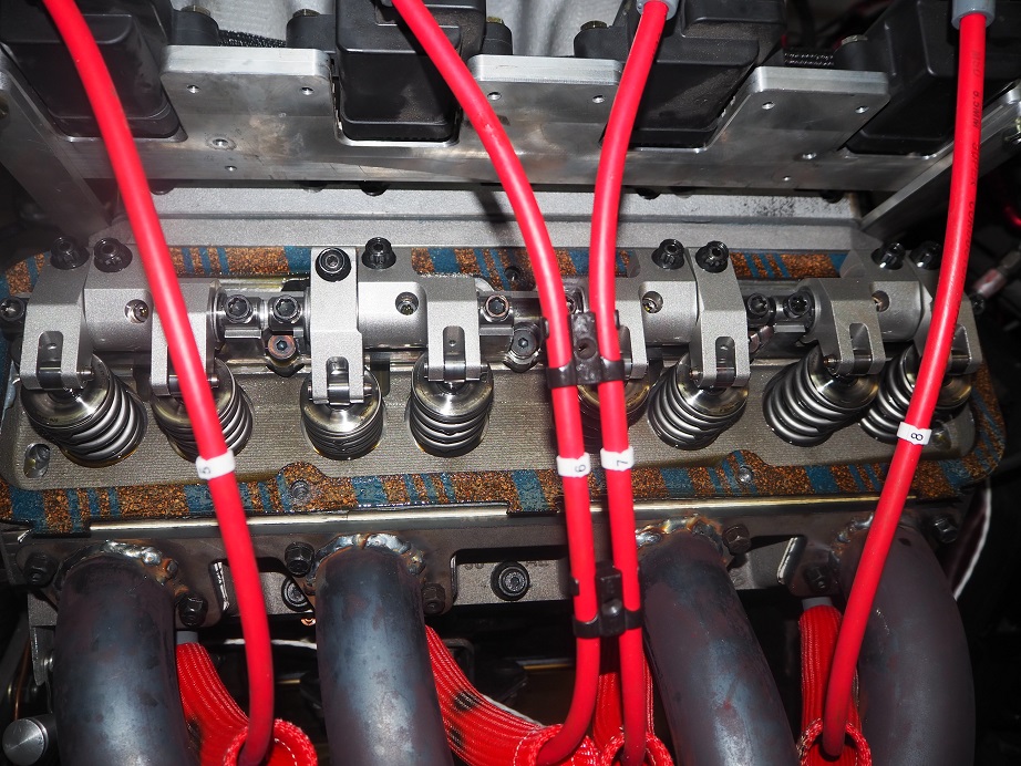
Here's what the engine looked like during most of the dyno testing:
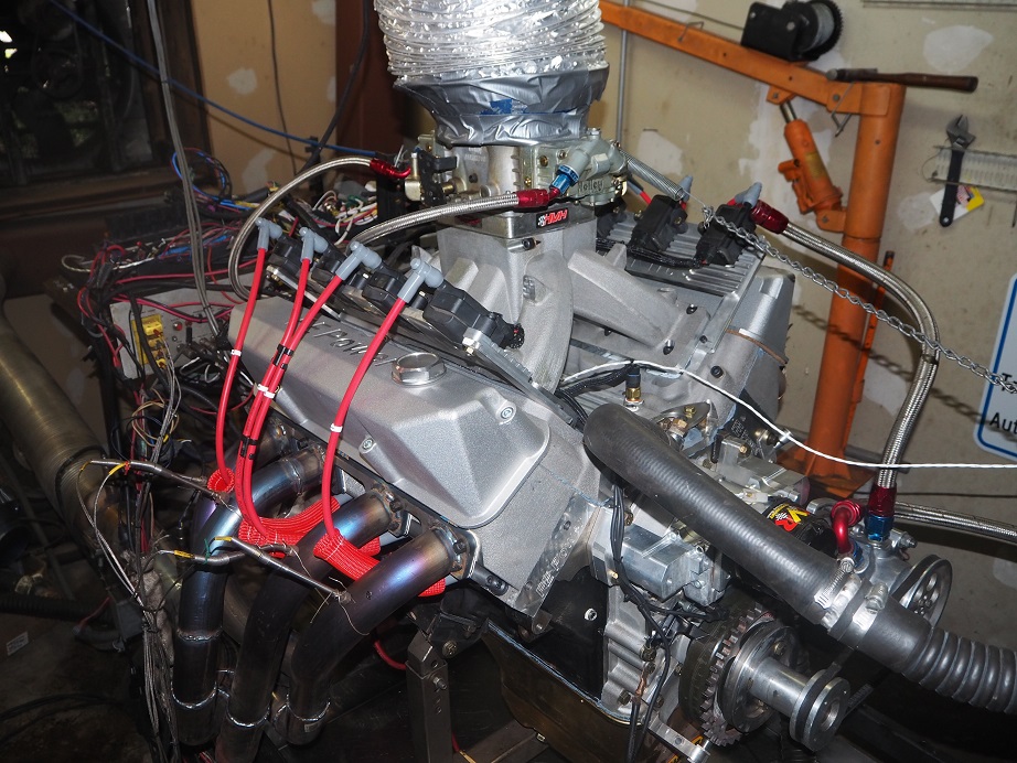
So far I have only tested the RE version of the cylinder heads. Most of the testing has been done with the 4V intake manifold, but I did make a few pulls with the 8V intake also. I was hoping for 850 HP out of the 4V intake and Dominator carb, and 900 HP out of the 8V intake and two 850 carbs. Testing has been interrupted numerous times with valve train problems, which I will try to describe in detail below. For now, this was the only pull to 7000 RPM with the 4V intake and Dominator carb:
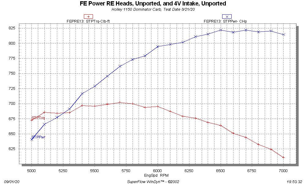
I guess 820 HP isn't too bad as a starting point. One notable thing about this dyno pull was that the manifold vacuum at 7000 RPM was 2 inches; that's a whole lot, and indicated that the carb could be too small. But that turned out not to be the case, from some later test results.
Backing up, I got the engine on the dyno in the middle of August, built the headers, and double and triple checked everything before starting to test. Starting it up was a real thrill; every cast aluminum part, and almost all the billet parts on this engine, started life on my computer screen. It was great to see all that work suddenly running an engine. I started it with the clear top valve covers so that I could watch the oil flow in the valvetrain area, and it looked just fine. Warm up was uneventful, and after running for about 15 minutes I shut the engine down to lash the valves, then installed the regular valve covers, which seal better when using the vacuum pump.
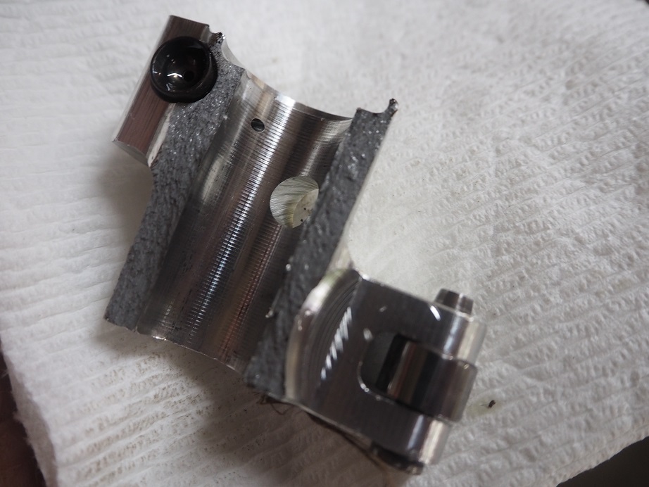
The next day Royce B came by to help with the testing. Kevin R was also there, and a few others. We started with a cruise test just to see how the air/fuel looked under load, and it seemed at the lower engine speeds it was OK, so we ran a dyno pull from 3000 to 4500, changed jets, ran from 3000 to 5000, jetted up again, and with the A/F looking good we started running higher. But, at the start of one of the pulls, while the engine was still warming up, we heard a noise that sounded like a bolt had dropped into the sheet metal pan on the dyno, under the engine. We went out and looked, but didn't see anything. On the next pull, we were down 75 horsepower from where we had been. I pulled the valve covers and discovered this broken intake rocker:
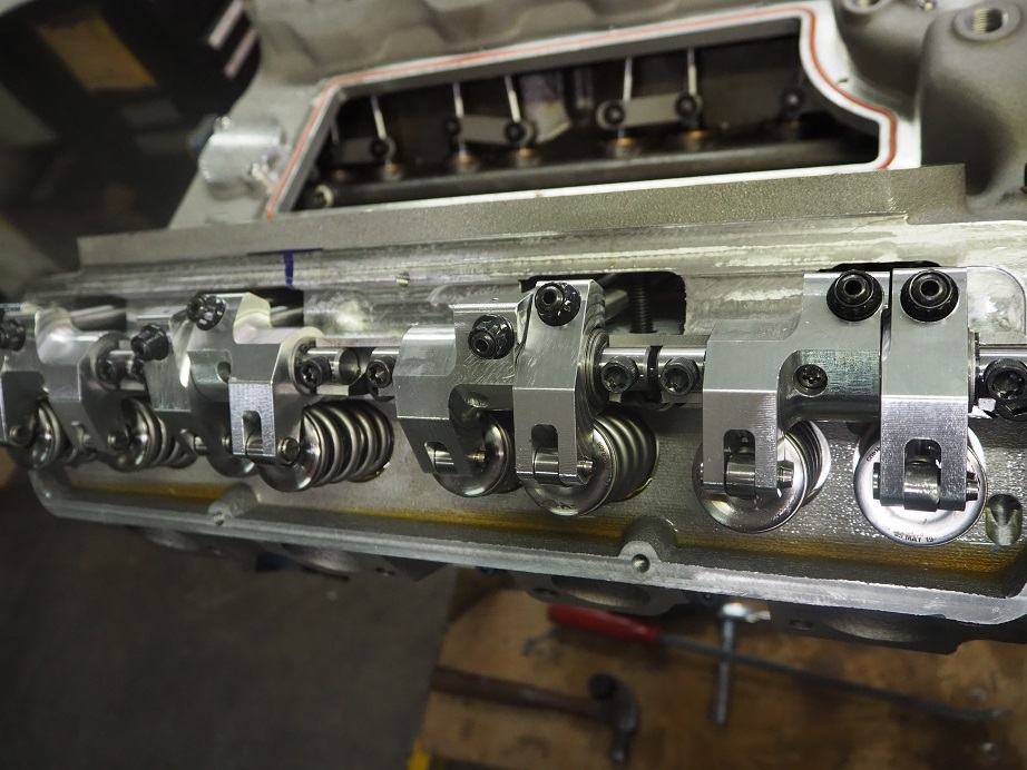
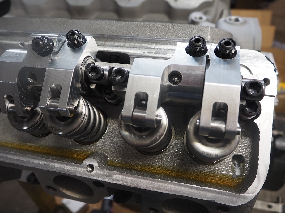
Just for reference, here are a couple of pictures of the intact valvetrain:
With the big valvesprings there are a lot of torsional stresses on that intake rocker. Bill Conley had helped me with an FEA analysis of the design, and it appeared that the design would hold, but it seemed that we were looking at a fatigue failure, rather than a strength issue. Looking at the broken rocker, you can see it is pretty thin over by the adjuster. Larry Tores at T&D Machine had mentioned to me at the PRI show last year that most fatigue failures start right in this area, so I figured that's what was happening.
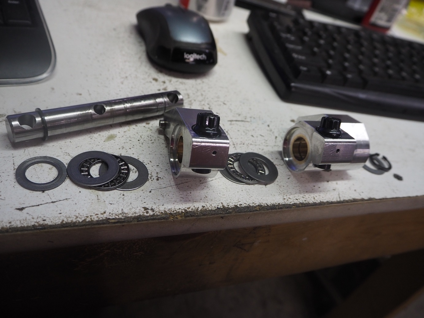
The reason that the rocker is thin there is that it is counterbored in that area for a thrust bearing. During the FEA analysis it became clear that the side loads on the intake rocker were going to be pretty large, due to the angled pushrod. So, I designed the intake rocker with a thrust bearing that bears against the exhaust rocker, and of course since the force is transmitted through the exhaust rocker, it needs a thrust bearing on the other side too. Here's a picture of a rocker pair assembly taken apart, showing the thrust bearings and the steel washers they ride against:
Well, it was possible that this was just a bad rocker, and I had a few spares, so we replaced that one and continued running. We had no further issues for the remaining dyno tests, and made the one pull from 5000 to 7000 RPM. I was very happy that the valvetrain seemed to hold together with no problem up to that engine speed. But it was, and still is, a mystery to me why the engine peaked in power at about 6500 RPM. I've got to believe that the cam wants to go higher than that.
Next, we pulled off the 4V intake and 1150 Dominator, and installed the 8V intake and two 850 center squirter carbs. I had really high hopes for this one, but unfortunately our testing was cut short by more rocker arm problems. The first pull with the 8V intake, and really the only good pull, was 3000 to 5000 RPM. The motor was pig rich, even showing some A/F numbers in the 9s, which you never see. Nevertheless, it still showed a lot of promise. The graph below shows the best 3000-5000 RPM pull with the 4V intake, and the first pull with the 8V intake:
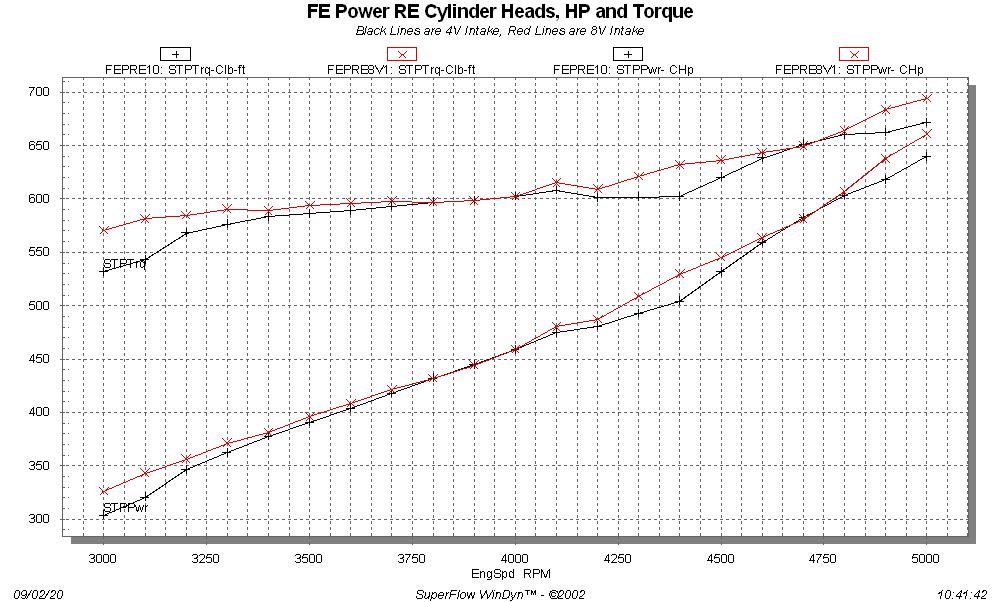
At 5000 RPM, despite being very rich, the 8V intake looks to be pulling away from the 4V intake, up by 20 HP to 660 HP at that point. But that was as good as it got. We jetted down, and for some unknown reason, A/F started looking better but power was down substantially. We tried another pull, and then the motor just didn't sound right. Pulled the valve covers, and found two more broken intake rockers. Crap

Done for the day.
The conclusions from the first round of testing were twofold: The intake rocker needed to be redesigned to add material around the adjuster, and the 4V intake needed to be tested with a bigger carb, to try to reduce vacuum at wide open throttle. On the intake rocker, I didn't have room to move the adjuster towards the thicker side, because then the pushrod would hit the intake adapter. But the exhaust rocker was thicker on both sides of the adjuster than the intake rocker was on it's thin side, and since the pushrod comes straight up for the exhaust rocker, it wouldn't be subject to the kind of torsional stresses that the intake rocker was. So, I moved the counterbore that had been in the intake rocker over to the exhaust rocker, to leave the intake rocker as thick as possible around the adjuster.
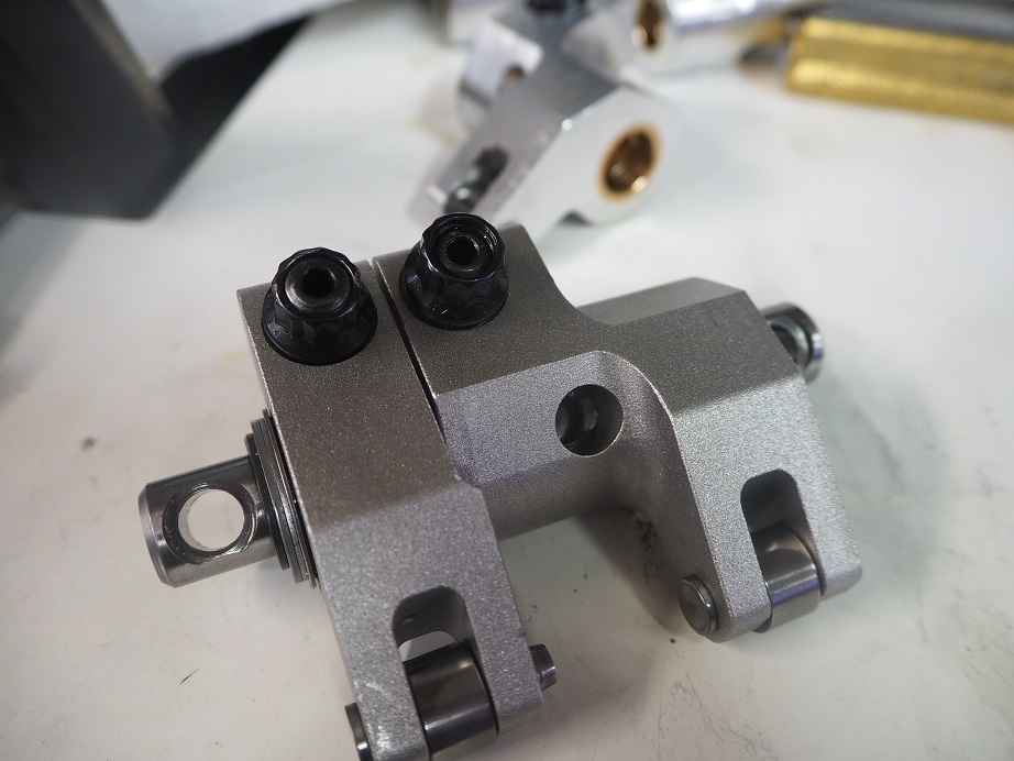
For the next few days I revised my CNC programming for the rocker arms and machined a new set of intake rockers, and modified the existing set of exhaust rockers. Along the way, Royce talked to Jon Kaase about the issues we were seeing (Royce knows Jon from his Engine Masters engines, and I've met Jon at the PRI show). Jon steered Royce to a guy who makes Kaase's top end rockers, and there was an online article about his parts. One of the things I found interesting in his article was that he shot peens his aluminum rocker arms. I thought this might be a good thing for me to do also, because machining aluminum creates tensile stresses on the outside of the material, and can lead to fatigue problems. Shot peening changes those to compressive stresses, which are more resistant to fatigue. I found a local company who could shot peen my rockers, so I dropped them off for the work. They were able to get it done in a couple days, and I got them back last Friday. Here's a couple pictures of the shot peened rockers:
In the meantime, Royce had found a guy with one of those billet body 1400 cfm Dominator carbs, who was willing to lend it to us for testing. He brought it up last Friday, but it took most of the afternoon to re-assemble the valvetrain. Installing it, we encountered a strange problem with the rockers; even with the adjusters backed all the way off, there was no lash. I found out later that shot peening can deform aluminum, and the shot peening operation had actually changed the dimensions of the rockers, leading to the problem. I shimmed up the stands to get some lash, but then when the rockers started getting cycled with the engine running, the lash started backing out; apparently the rockers were relaxing into the original machined shape. I won't go into all the details, but this led to some weird noises from the valvetrain, that we finally figured out were broken adjusters; continually adjusting the lash had left them sticking too far out of the rocker arms.
Finally by Saturday afternoon we had this all ironed out, engine was running fine, no more lash issues, etc., and were ready to make a pull with the 4V intake and the big Dominator carb. But I think we only made one pull, when Royce noticed some smoke coming out of the vacuum pump catch can when the engine was running. We pulled the valve covers again, and on the left side I noticed that we had water in the oil. Ugh

So, one of the nightmare scenarios with these heads was that they wouldn't hold up to punishment under running conditions, despite the thick walls I had put into the casting design. However, the problem turned out to be the intake gasket, which was leaking water at the rear water opening of the right head. Sunday I pressurized the cooling system to find the leak, and then pulled the intake adapter off. When I looked at it in detail it became plain that I had machined the intake adapter incorrectly, and not left enough material to completely cover the gasket over the hole in the rear of the head. If I had installed the intake adapter without a gasket, I'd have seen about a .040" slot of the rear water opening in the head exposed. The gasket held there for a while, but finally gave up on Saturday afternoon. Another simple issue, that will be easy to fix with a correction to the machining program, but it stopped us in our tracks on Saturday.
By the end of the day Monday I had made up some thin brass plates to block off the rear water jacket holes in the heads, and re-installed the intake adapter and valvetrain. Tuesday I ran the engine again, with the 4V intake and the big carb, but encountered another problem with the #8 exhaust rocker. During operation, it was jamming the adjuster back into the body of the rocker arm, opening the lash way up. #8 had been one of the cylinders where one of the intake rockers had failed during a pull, and I'd been wondering if I'd done some damage in one of those cylinders. This morning I fabricated a tool to remove the valve springs with the heads on the engine, and did a leakdown check on #8, and sure enough the exhaust valve is bent. I'm thinking the bent valve contacted the piston and jammed the adjuster up into the rocker arm.
I did get some good data up to 6000 RPM with the big carb, and much to my surprise, the engine was pulling the same amount of vacuum that the 1150 Dominator was at the same speeds. I don't think there's any way that carb is too small, so now I'm suspecting the 4V intake manifold is a restriction, and probably limiting power production. I've been talking to Joe Craine, and he has agreed to flow both the 4V and 8V intakes, on the intake adapter, and make some modifications to improve them. Anyone who has been following this project probably remembers that my first go around with the RE heads showed exhaust flow that was not that great; I sent part of a head down to Joe and he modified the port to work better. Then I took the modifications and incorporated them into the casting patterns, and the exhaust ports as cast picked up about 40 cfm. I'm hoping that Joe can find some improvements in the intake manifolds, that I can also incorporate into revised castings.
I remain surprised by the relatively low RPM where this engine wants to peak in power. I supposed it could be related to the intakes, but with a 285/292 @ .050 cam, I was figuring it would peak well over 7000 RPM. I suppose it could be intake related, so we'll find out if that's the case when I dyno again with Joe's improvements.
Also, I've been thinking that I need to go to steel rocker arms on this setup. Even though I haven't broken any more intake rockers since the design change, I've lost some confidence in them as a result, and would like a more bulletproof part. I think while I am waiting for valves, and for Joe to flow the intakes, I will work on getting a revised design for a steel rocker arm finished and machined. I'm also looking at an investment casting option for the steel rockers.
I will be back on the dyno with this engine as soon as possible, hopefully by the end of the month. I'm not sure if I've fleshed out all the problems yet, but I've certainly identified the most obvious ones, so next time around the testing should go quite a bit smoother.


