I thought you guys might enjoy seeing the casting process for my new cylinder heads. I got finished with the final revision of my cylinder head design a couple months ago. After designing the heads and intake systems, I ended up designing all the patterns required for pouring the aluminum for these heads, trying to save on the cost of going to a pattern shop. Along the way I've been fortunate to get acquainted with a guy at a local university who runs their Additive Manufacturing Center, where they do a bunch of 3D printing. One of the things they 3D print is sand, used for cores in making sand molds for pouring molten metal. As it happens, this guy also has a 68 Torino and a 428 for it, which I'm currently building for him. So, I can help him out, and he is certainly helping me out with the casting side of my head project.
I sent the files for the cylinder heads to this guy, and he enlisted the help of one of their students to go over the design. They ended up changing the whole approach that I had used for pouring the metal; in other words, a new sprue, new gating, and new riser designs. Then they simulated the design with some casting simulation software, and tweaked the gating and riser design until the simulation said that the finished casting would be solid, with little or no porosity.
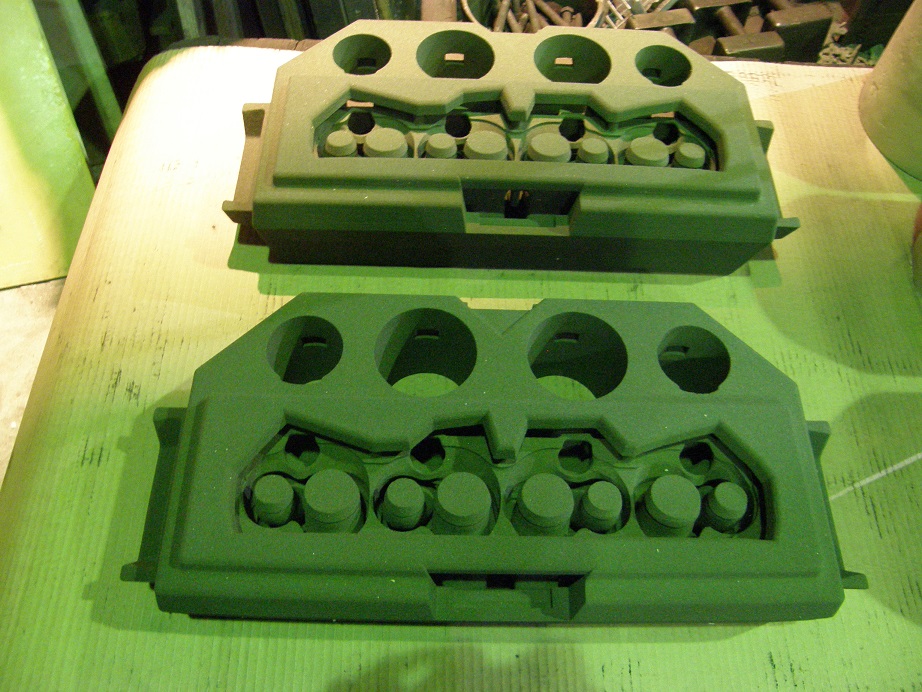
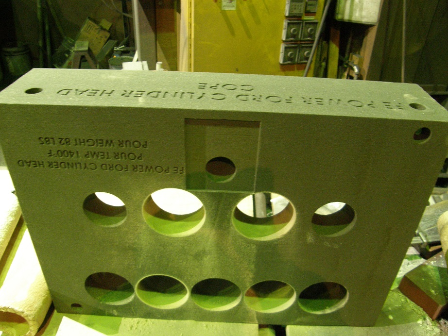
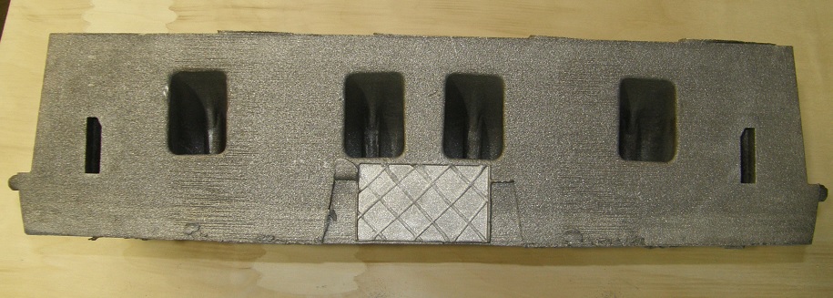
Once that was finished, they 3D printed the sand required for two cylinder head castings, and shipped it over to my foundry. Today was the big day, where we poured the first head. The first sand mold used is the bottom, called the drag, and pictured below:

The picture was taken in the foundry, where it is rather dark, and when using the flash a bunch of the details are washed out, so this photo was taken without the flash. Some of the pictures are kind of blurry because of this, and they all have a sort of green tint to them, but you'll get the idea. Looking at the drag, you can see the shape of the combustion chambers, and the holes in the middle of the chambers where the core for the ports fit in. Also in this picture you can see the chill, which is a small block of steel that causes the aluminum to solidify more quickly and helps to eliminate porosity. The chill was added here because the simulations showed that porosity could be a problem in this area. Also toward the front of the drag you can see four large holes, where risers are designed in, and also a channel that the aluminum goes into when it is first poured.
This next photo is the core, which basically forms the ports, water jacket, and side surfaces of the cylinder head. There are two of the cores in this photo. The picture shows the cores upside down, and you can see the cone shaped areas on the ports that fit into the drag:
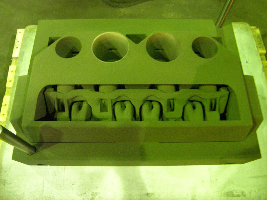
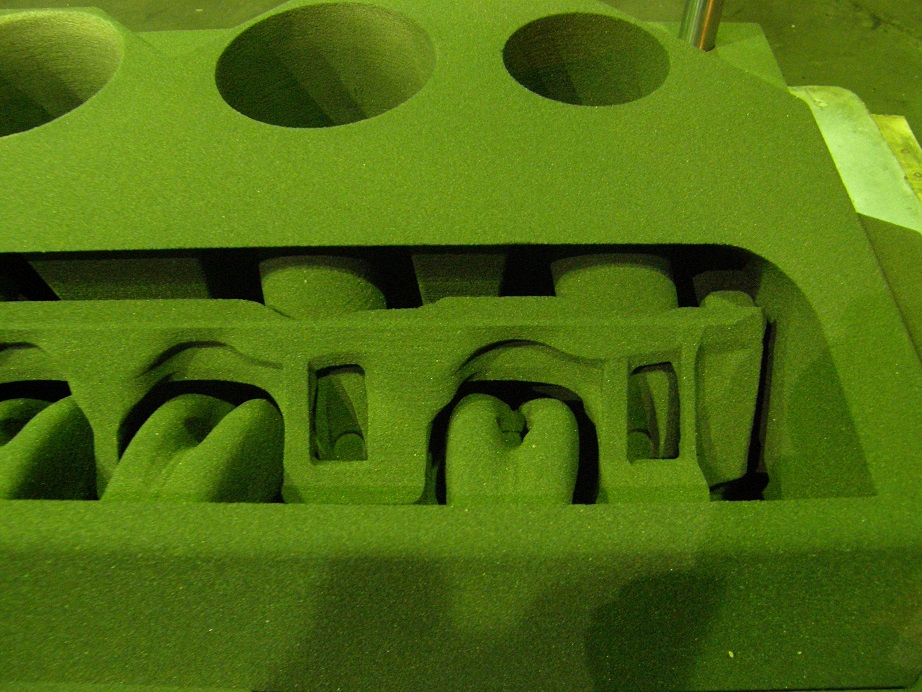
The next photo shows the core assembled into the drag. There's also a close up photo of the top of the core, so that you can see what the top of the port cores look like. Finally, the third photo below shows this same assembly from a different angle, where you can see the filter that is used to filter the molten aluminum as it is poured into the mold:
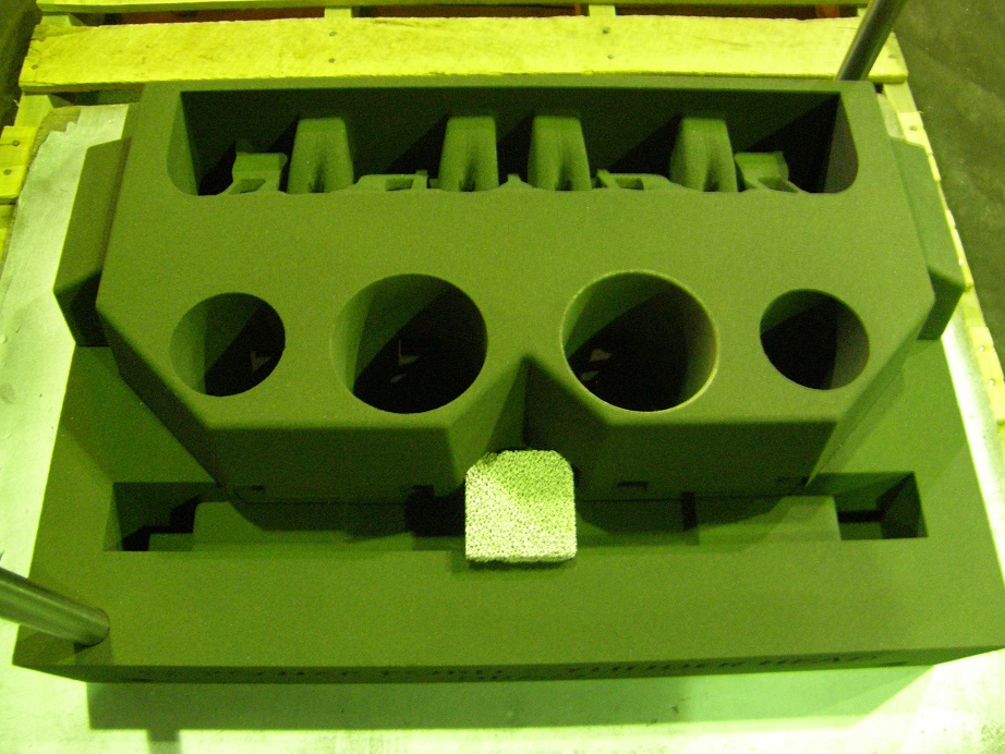
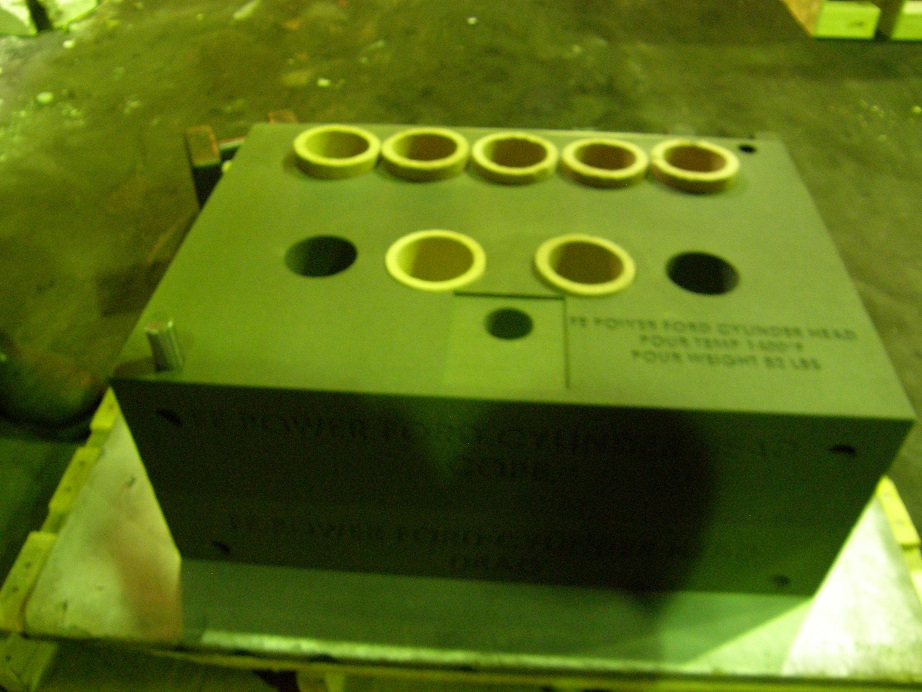
The two 1" diameter steel pins in the previous photo are used to help align the drag and core with the cope, which is the top of the mold. Here's a photo of the top of the cope:
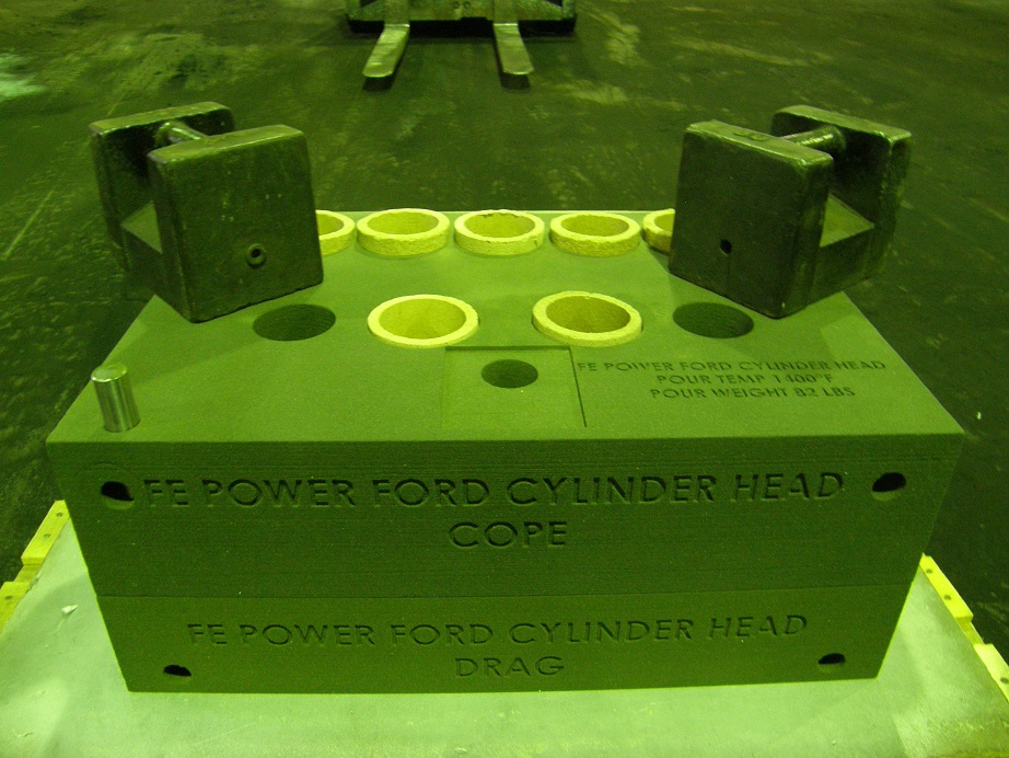
And here is a photo of the entire mold assembled, with the cope positioned on top. Notice the sleeves in the risers (large holes); these are made of an insulating material and are designed to keep the aluminum hot as long as possible. As it cools, the aluminum in the head shrinks, and molten aluminum from the risers has to feed back into the rest of the mold to keep the casting from developing porous areas. Keeping the risers hot as long as possible is one key consideration when making a good casting.
Before the mold is poured, the lead weights shown in the picture below are set on top of the cope. This is to prevent the cope and the core from floating up on the liquid aluminum as it is poured into the mold. I think this is because the sand cores are not as dense as the liquid aluminum, and can actually float up on the denser aluminum.
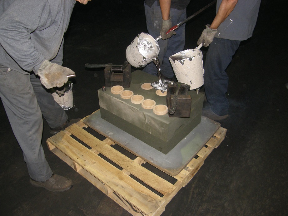
Now the mold is ready for the pour. At the foundry I use this is done by hand, using crucibles that hold around 35 pounds of molten aluminum. Here are two pictures of the pouring process; I was able to get one good one with the flash:
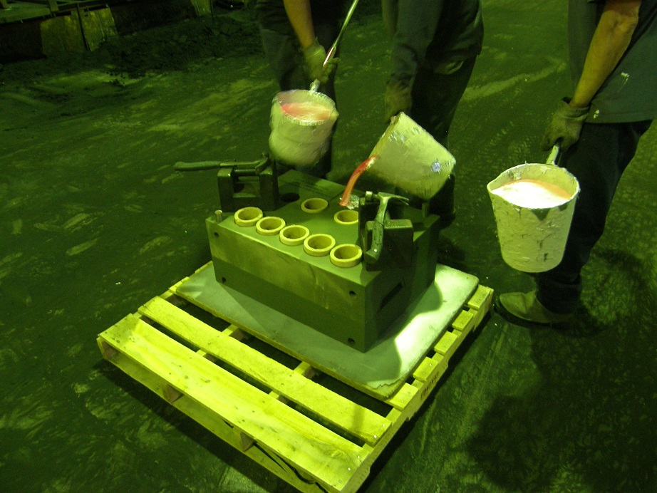
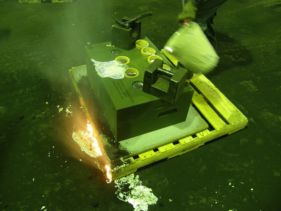
After the mold if filled with aluminum, for several minutes the foundry guys continue to slowly pour liquid aluminum into the risers. This helps keep the aluminum in the risers hot, so that it can feed into the rest of the casting as it cools. They call this hot topping:
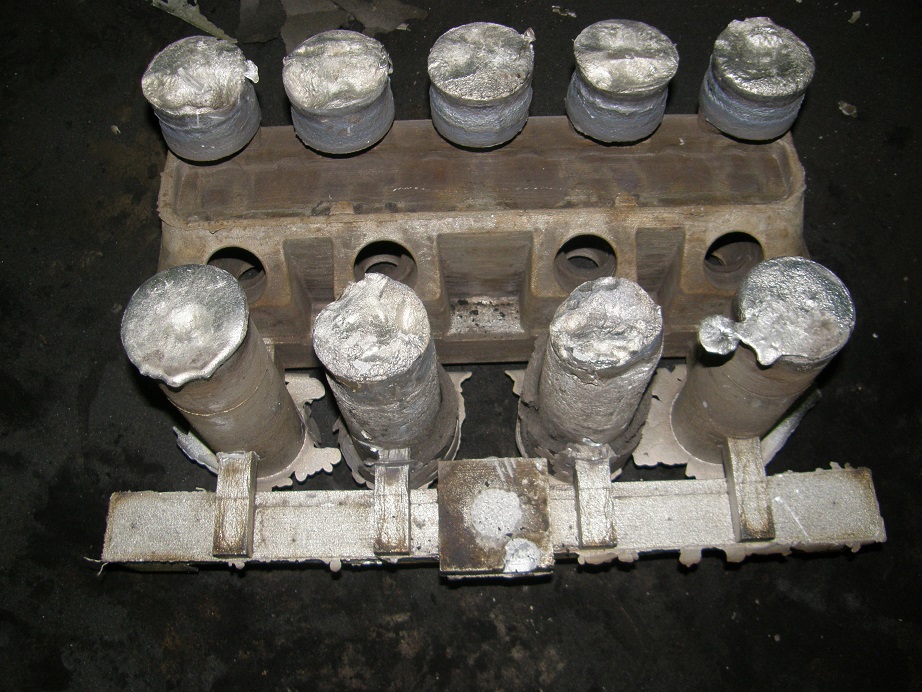
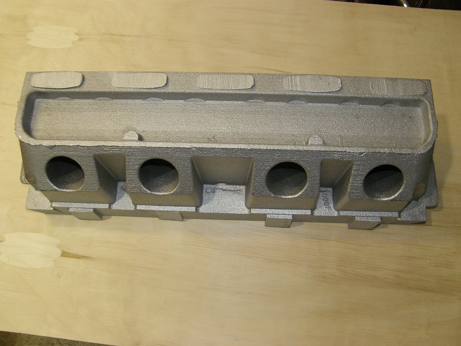
After waiting 45 minutes or so, the casting has cooled to the point where it can be broken out of the sand. The 3D printed sand is more difficult to remove than the normal sand used by the foundry, but after some serious beating with hammers and air chisels most of the sand came off. The sand in the water jacket of the cylinder head was difficult to remove, and I can see that this is going to be something I will have to focus on with these heads. But after a while we got it all out, as far as we can tell. I will be running some rods through the water jacket openings in the casting I took home today to try to make sure that no sand remains. Here are some pictures of the casting as it was broken out of the mold:


After another couple hours the casting was cooled enough to handle, and was trimmed with a saw to remove all the gating and risers. Here are some pictures of the finished head casting that I took home today:
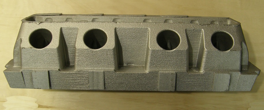
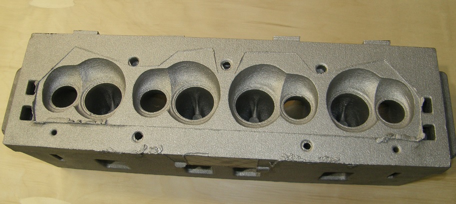
Of course, as it stands this is just the beginning for this casting. It needs to be solution heat treated to a T-6 condition, then I need to machine it here on my CNC machine. It will need seats and guides installed and a good valve job done, then I can flow test it and also pressure check it. I'm going to try to get this done ASAP, but heat treating will take a couple weeks, and I will also need to machine a fixture for holding the heads on my CNC machine, and then develop all the machining programs to get this done. I have a second head being cast tomorrow so assuming everything is good with these two heads, I should be able to run them on an engine this spring. If I find that things aren't quite right as I go forward with this process, I will have to revamp the design and cast more of these heads. To be honest, I fully expect at least one or two iterations will be required before they are ready for sale. But getting the first head cast is a big step, and I'm happy with the results so far. I will post more info in this thread as the project progresses - Jay


