Author Topic: FE Intake Adapter  (Read 356601 times)

0 Members and 1 Guest are viewing this topic.

cjshaker

  • Hero Member
  • *****
  • Posts: 4540
    • View Profile
Re: FE Intake Adapter
« Reply #315 on: September 09, 2013, 07:46:51 PM »
I'm going to cut the whole center out. It won't cause a problem. It's a casting, so there is no tension anywhere in the part to cause movement if it's cut. Not like a welded piece that places stress on certain areas.

If you cut the center out, the outer tubes will not move. I think it will look better, weigh less....and probably improve flow by at least 10%-15%.  ;)
Doug Smith


'69 R-code Mach 1, 427 MR, 2x4, Jerico, 4.30 Locker
'70 F-350 390
'55 Ford Customline 2dr
'37 Ford Coupe

NewFalconOwner

  • Guest
Re: FE Intake Adapter
« Reply #316 on: September 10, 2013, 04:10:42 PM »
thanx :)

NewFalconOwner

  • Guest
Re: FE Intake Adapter
« Reply #317 on: September 10, 2013, 05:54:54 PM »
« Last Edit: September 10, 2013, 06:05:27 PM by NewFalconOwner »

Jim-W

  • Newbie
  • *
  • Posts: 22
    • View Profile
Re: FE Intake Adapter
« Reply #318 on: September 10, 2013, 11:28:52 PM »
Oh wow! that's interesting. Wonder if it flows worth a darn? wouldn't that be fun having a dual 4 intake to drop on in 15 minutes... Hmm So many possibilities!  ;D

jayb

  • Administrator
  • Hero Member
  • *****
  • Posts: 7585
    • View Profile
    • FE Power
Re: FE Intake Adapter
« Reply #319 on: September 11, 2013, 08:03:36 AM »
That is a cool looking intake, but it looks like it has a huge open plenum under the carbs.  I don't know how well it would work but I'd be a little concerned that it would lack low end and mid range...
Jay Brown
- 1969 Mach 1, Drag Week 2005 Winner NA/BB, 511" FE (10.60s @ 129); Drag Week 2007 Runner-Up PA/BB, 490" Supercharged FE (9.35 @ 151)
- 1964 Ford Galaxie, Drag Week 2009 Winner Modified NA (9.50s @ 143), 585" SOHC
- 1969 Shelby Clone, Drag Week 2015 Winner Modified NA (Average 8.98 @ 149), 585" SOHC


NewFalconOwner

  • Guest
Re: FE Intake Adapter
« Reply #320 on: September 12, 2013, 11:37:02 AM »
be a great blower manifold with their plate


jayb

  • Administrator
  • Hero Member
  • *****
  • Posts: 7585
    • View Profile
    • FE Power
Re: FE Intake Adapter
« Reply #321 on: September 12, 2013, 11:41:53 AM »
Hey, you are right about that!  I didn't know that plate was available...
Jay Brown
- 1969 Mach 1, Drag Week 2005 Winner NA/BB, 511" FE (10.60s @ 129); Drag Week 2007 Runner-Up PA/BB, 490" Supercharged FE (9.35 @ 151)
- 1964 Ford Galaxie, Drag Week 2009 Winner Modified NA (9.50s @ 143), 585" SOHC
- 1969 Shelby Clone, Drag Week 2015 Winner Modified NA (Average 8.98 @ 149), 585" SOHC


jayb

  • Administrator
  • Hero Member
  • *****
  • Posts: 7585
    • View Profile
    • FE Power
Re: FE Intake Adapter
« Reply #322 on: September 26, 2013, 08:55:55 PM »
As usual things are slightly behind schedule on this project, but today I was able to run off at my lunch break and watch the action at the foundry.  What an education!  It was really cool watching the guys in the foundry put together the sand molds for the manifolds and cast them.  I only had about a half hour to watch, but they did one for me from start to finish so I could take a bunch of pictures.  Unfortunately, the battery in my camera got weak after a few shots and I had to discontinue using the flash.  The foundry is kind of dark inside, not the ideal environment for photos, and so after the flash went out the exposure times got long, and some of the following shots are blurry, with kind of a greenish cast to them.  Figures that the camera picked today to run out of juice; oh well.  You guys will get the idea from the photos below.

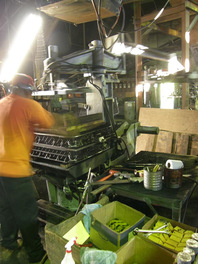
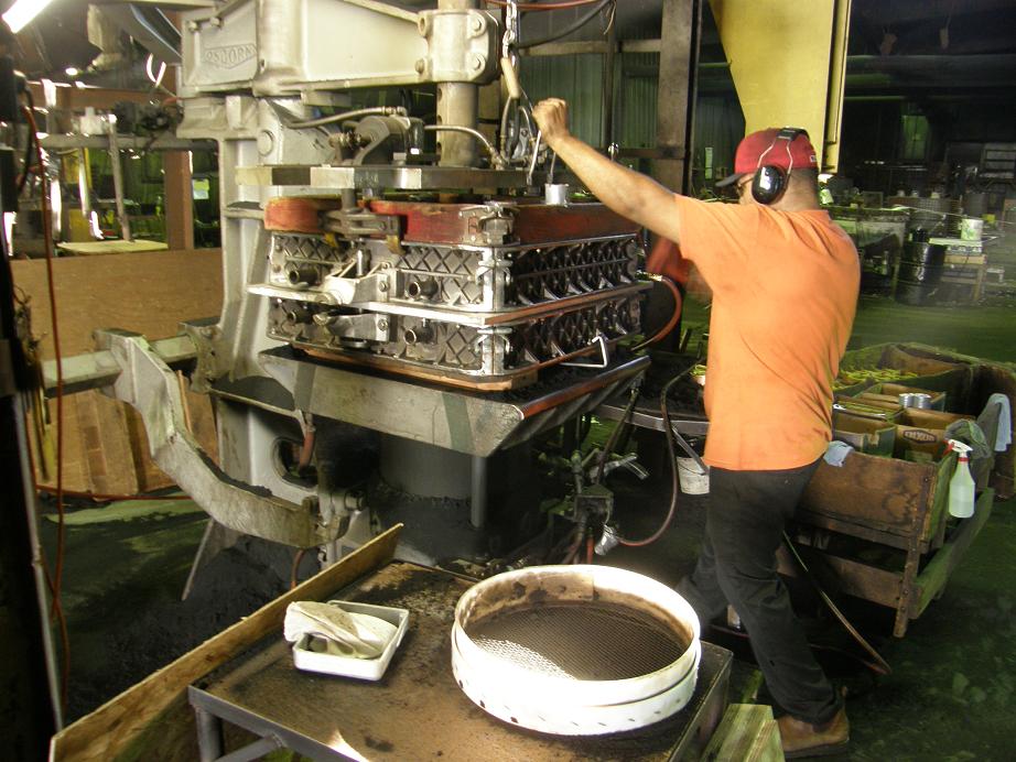
The machine in the photo below is the one they are using to make the sand molds for the intake manifold.  I think it is called a Roto-Lift machine.


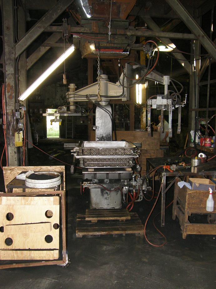
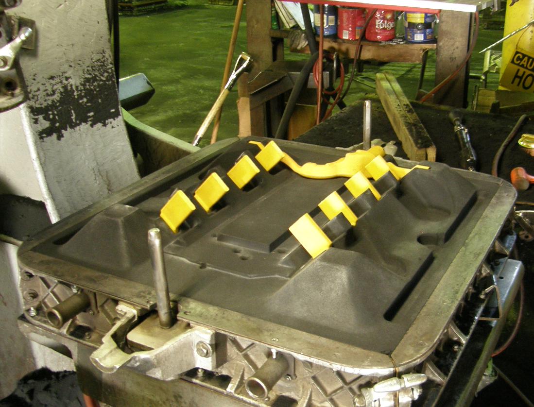
Here is a photo of the match plate, installed between two boxes to contain the sand.  I think the boxes are referred to as flasks, or maybe as a cope and a drag, in foundry parlance.  This assembly is positioned on the Roto-Lift machine so that the sand can be poured into the boxes and rammed in place.


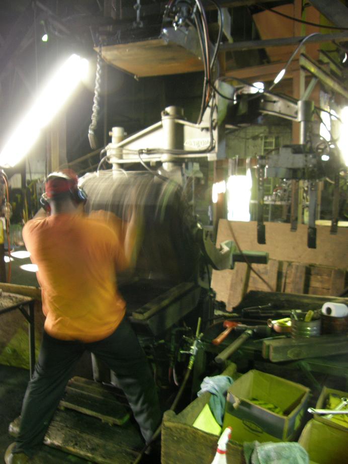
The bottom of the intake manifold is done first.  The Roto-Lift machine allows the match plate and flasks to be rotated together, so they are rotated upside down, with the bottom of the match plate facing up.  Then an overhead trap door opens and sand is poured down into the top of the flask.  You can see the sand pouring down into the flask  in the photo below.


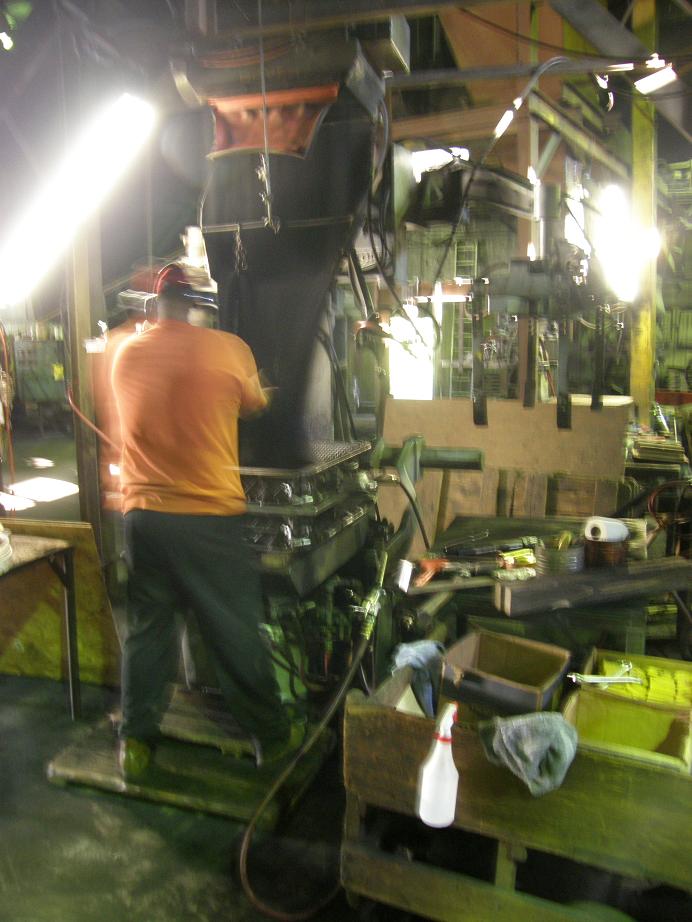
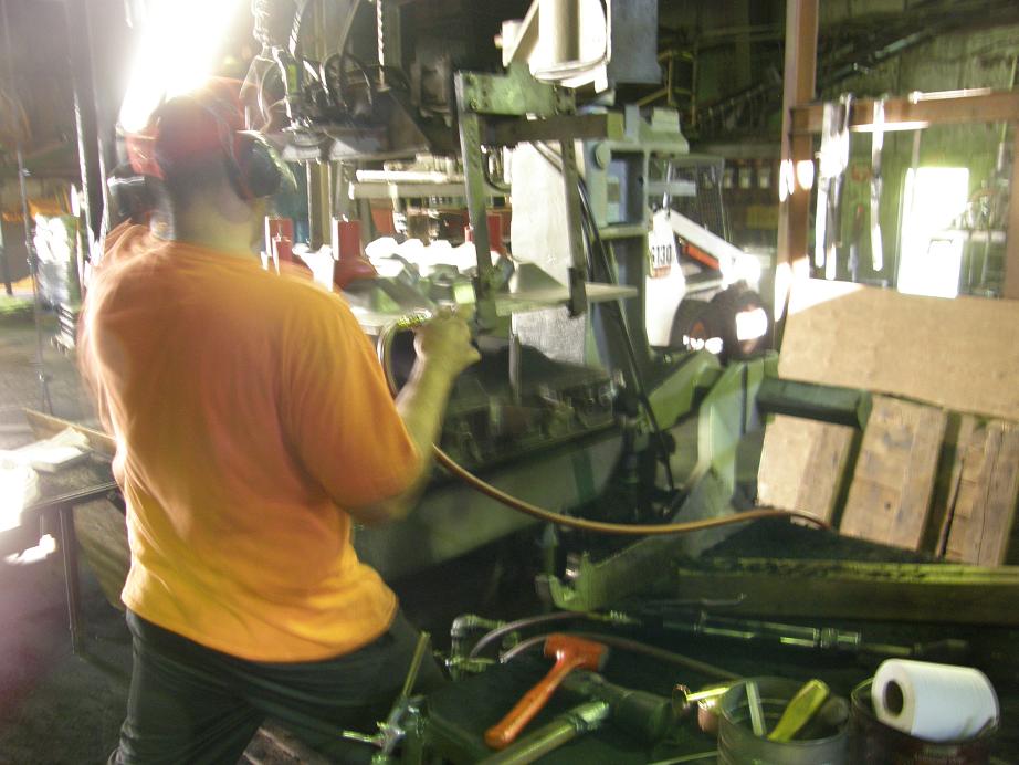
The operator doing this work was a guy named Mario.  He explained what he was doing as he went along to help me understand the process.  As the sand was filling in the box Mario was working with it, spreading it around and ramming some of it down by hand.  Finally after a few dumps of sand he had the box completely filled up as shown in the photo below:


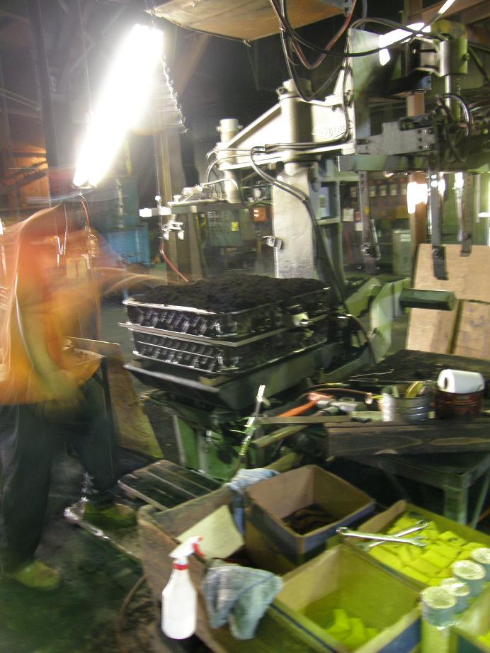
Next Mario put a wood cover over the box in preparation for ramming the sand with the Roto-Lift machine.  This process applies what I assume to be a very large downward pressure on the sand; this locks the sharp edges of the grains of sand together so that they will stay in place when the match plate is removed from the assembly.  Picture below.


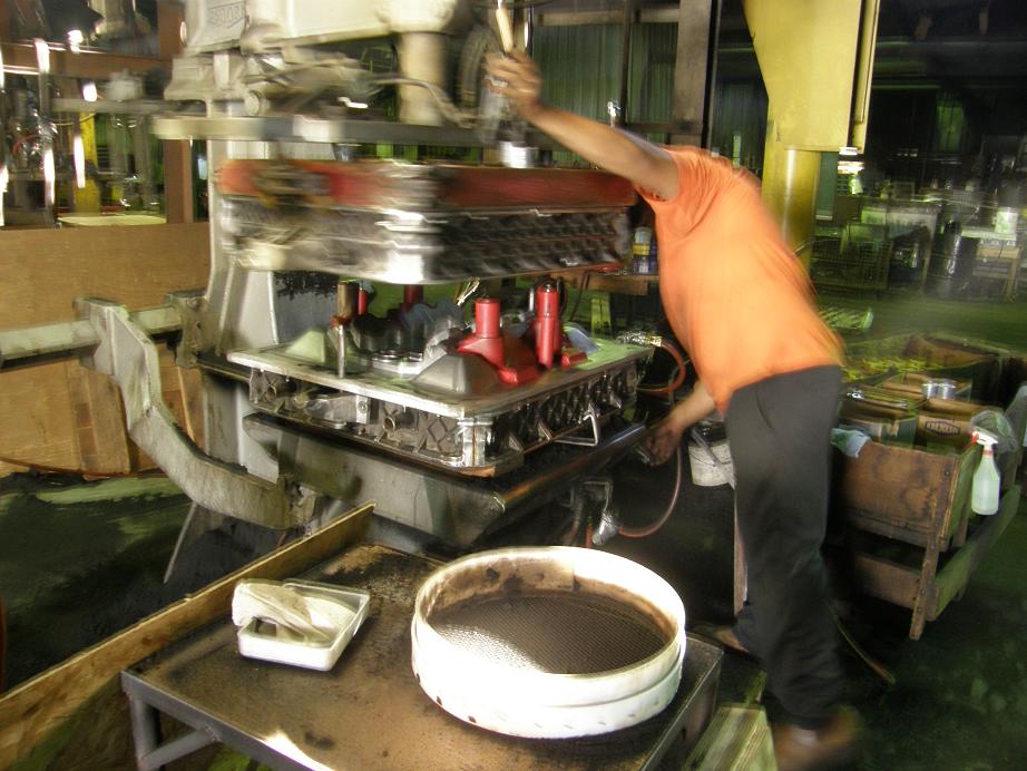
After the ramming process is finished the match plate and flask assembly is rotated 180 degrees on the Roto-Lift machine, so that now the top side of the match plate is facing up.  The picture below is one of those long exposure pictures, but you can see the blur of the assembly as Mario rotates it 180 degrees, and then with the top side of the match plate facing up:


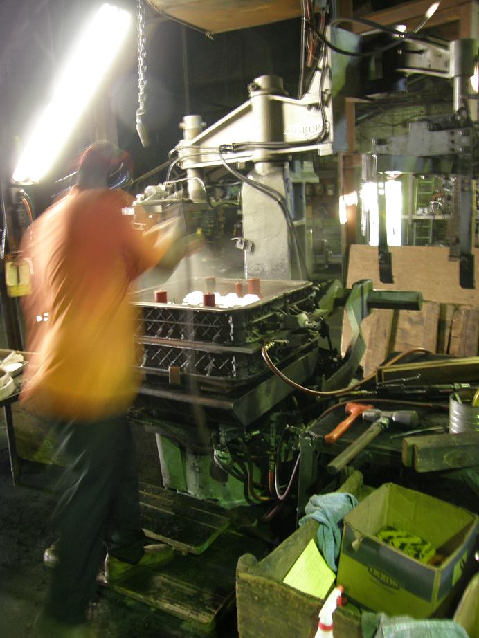
Next the same process is repeated on the top side of the sand mold.  The picture below shows the top side of the assembly being rammed by the Roto-Lift machine:


Next it is time to separate the match plate from the sand mold.  The match plate is vibrated by the Roto-Lift machine to free any sticking sand, and then the top side of the mold is pulled straight up by the machine to separate the sand mold from the match plate.  After separation the top half of the sand mold is rotated off to the left; see the photos below:


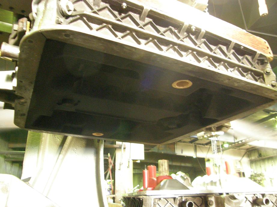
Here's a photo I took looking up underneath the top half of the sand mold.  You can see the impression in the sand from the match plate.  I believe they told me that there is about 500 pounds of sand used for each of these molds, so that is 250 pounds of sand hanging up there in the air, maintaining the shape of the match plate.  Unbelievable...


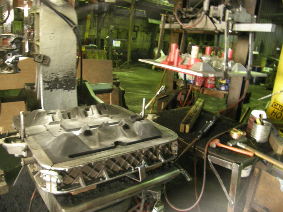
Next Mario repeats the same process where the match plate is vibrated to free it up from the sand, and then he uses the Roto-Lift machine to lift the match plate off the bottom sand mold.  The second photo shows the match plate on the right and the bottom sand mold on the left:


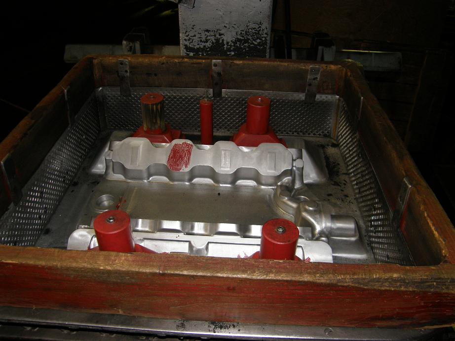
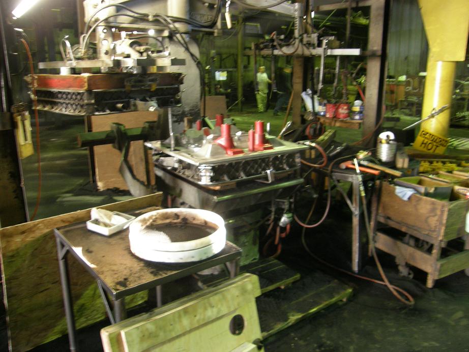
Next the cores have to be put into the mold.  The cores are made with a different process, and using a different kind of sand called no-bake or airset sand.  This sand is bound together with some kind of a chemical binder.  The sand used in the rest of the mold is called green sand.  The green sand is re-usable; the airset sand is not.  Further, the chemical used as a binder in the airset sand has to be properly disposed of for environmental reasons, and this gets pretty expensive with a 500 pound mold, so I elected to go with the green sand for the main part of the mold.  The downside to green sand is that tooling for green sand is more expensive.  Mario carefully placed the 8 port cores and the water jacket core into the bottom sand mold.  Here are some pictures of the cores, which were pre-made by the foundry, and a photo showing all the cores in place in the mold:


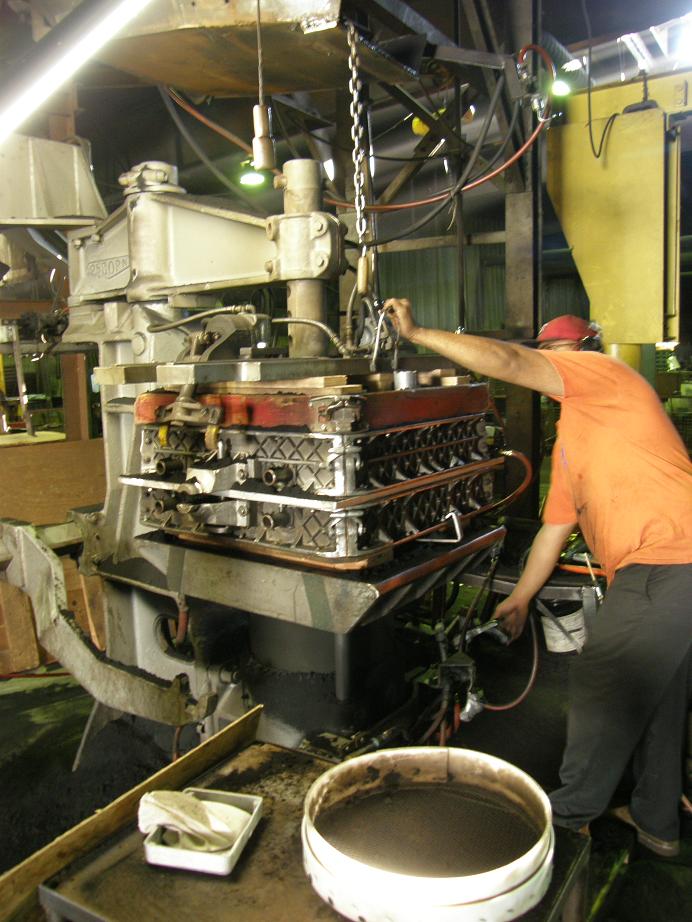
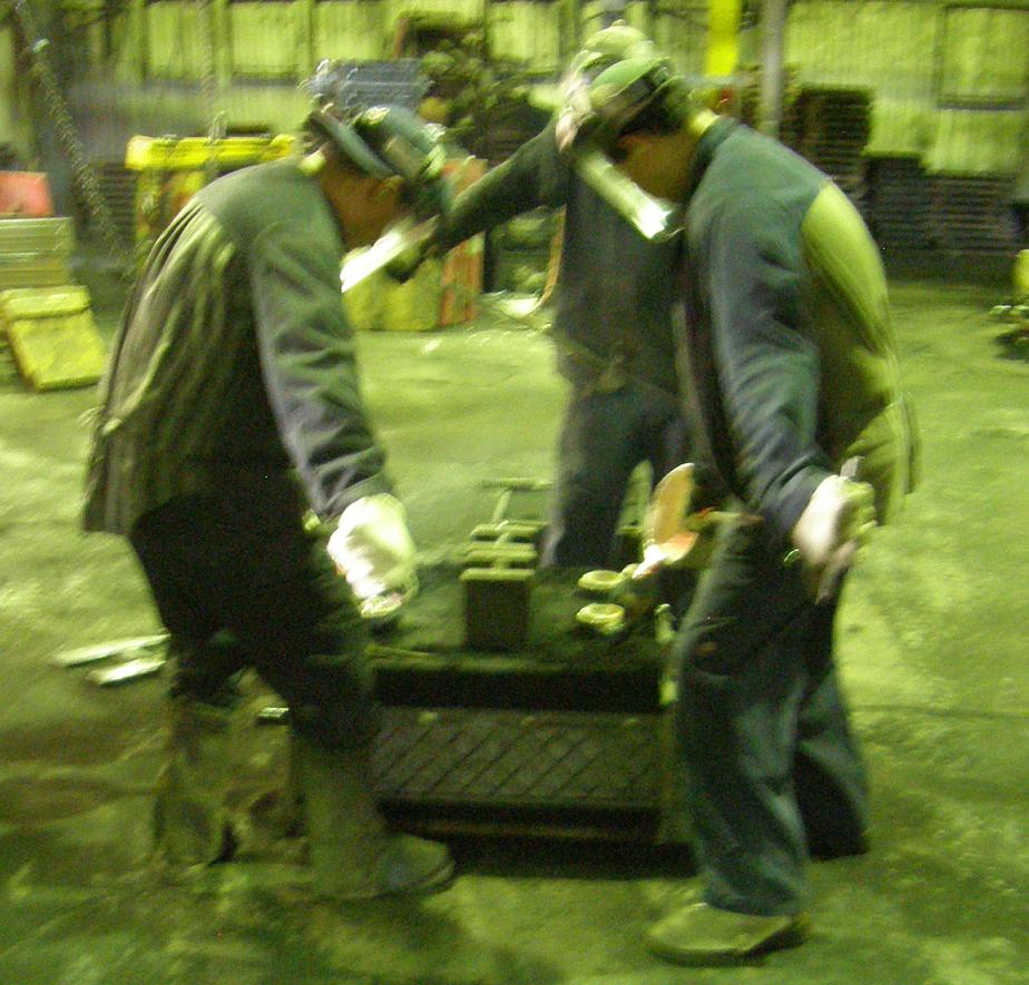
Next the two halves of the mold are put back together on the Roto-Lift machine, and then Mario uses a rotating crane with an electric lift to pick the whole mold assembly up and move it to the pouring area.  They use three operators pouring at once to fill the mold; I apologize for the very poor quality of this picture, but I'm sure you get the idea:


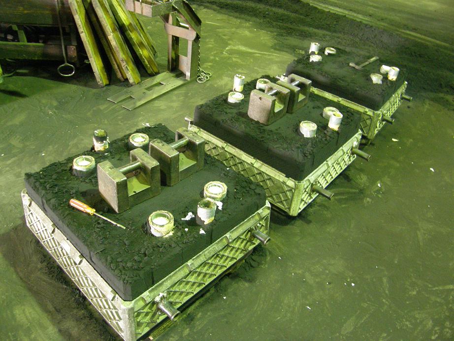
After pouring the casting is allowed to cool in the mold for a while; here's three of them lined up cooling, waiting to be broken out of the mold:


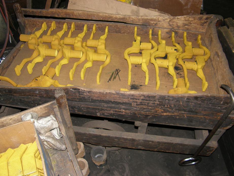
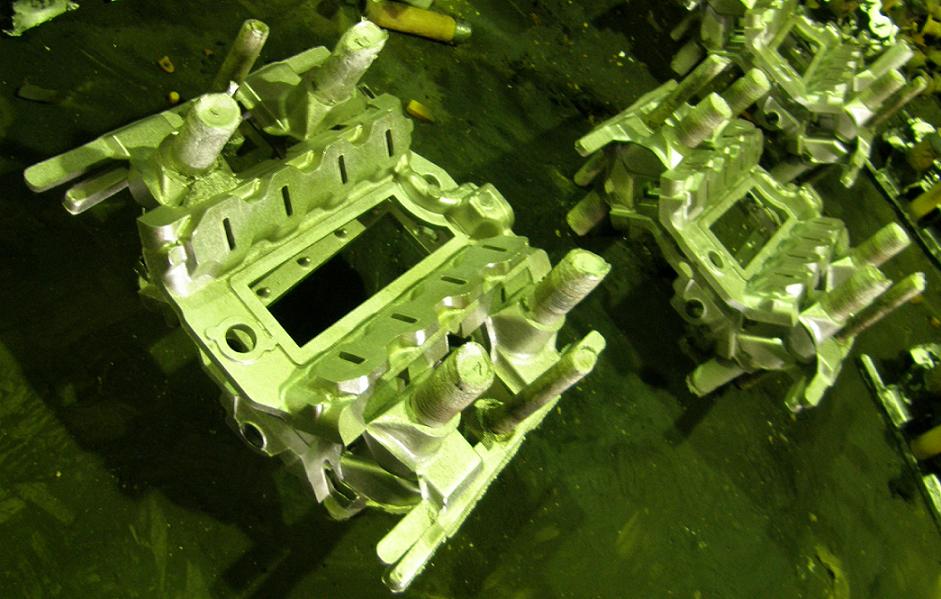
And here's a photo of a few of the castings that have been broken out of the mold, and still have the risers attached:


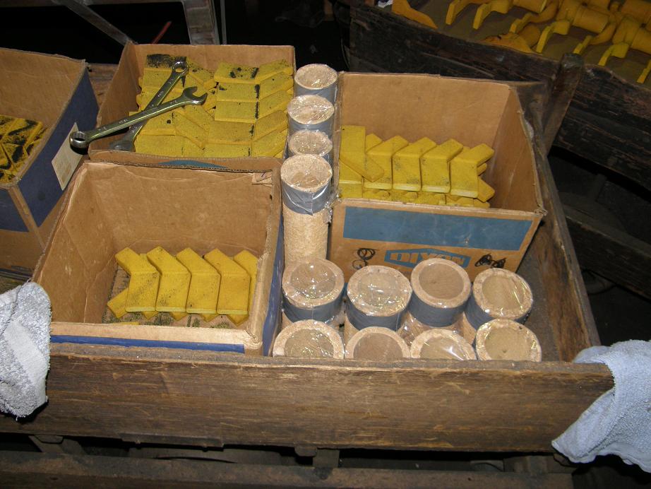
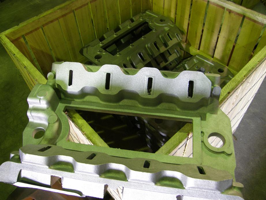
After they cool completely the castings are trimmed to remove the excess aluminum, and put in a box to get ready for shipment to the heat treat plant.  Here's a box of the castings, with one on top so that you can get a better idea of what they look like at this stage:


It sure was fun to see that whole process today.  I believe that the first 50 castings are going out to heat treat next week, so once I get them back I can start machining them here.  I'll post more photos when I get the castings back at my shop - Jay
Jay Brown
- 1969 Mach 1, Drag Week 2005 Winner NA/BB, 511" FE (10.60s @ 129); Drag Week 2007 Runner-Up PA/BB, 490" Supercharged FE (9.35 @ 151)
- 1964 Ford Galaxie, Drag Week 2009 Winner Modified NA (9.50s @ 143), 585" SOHC
- 1969 Shelby Clone, Drag Week 2015 Winner Modified NA (Average 8.98 @ 149), 585" SOHC


427Fastback

  • Hero Member
  • *****
  • Posts: 623
    • View Profile
Re: FE Intake Adapter
« Reply #323 on: September 26, 2013, 11:05:42 PM »
That is very interesting stuff...Would love to have seen it in person...I find it kind of cool to know that two or possibly three of those are headed my way....Well done..........Cory
1968 Mustang Fastback...427 MR 5spd (owned since 1977)
1967 Mustang coupe...Trans Am replica
1936 Diamond T 212BD
1990 Grizzly pick-up

JamesonRacing

  • Sr. Member
  • ****
  • Posts: 369
  • 1966 - What a great year for FOMOCO
    • View Profile
Re: FE Intake Adapter
« Reply #324 on: September 27, 2013, 08:36:37 AM »
What feature is used on the casting for your machining datum?  How does the casting process maintain the necessary features?

Great stuff, really eager to have one to install on my race car.
1966 Fairlane GT, Silver Blue/Black 496/C4 (9.93@133)
1966 Fairlane GT, Nightmist Blue/Black 465/TKO (11.41@122)
1966 Fairlane GTA Conv, Antique Bronze/Black, 418EFI/C6
1966 F250 C/S, Rangoon Red, 445/T19
1965 Falcon Futura 4-door, Turquoise, EF! Z2363/4R70W

turbohunter

  • Hero Member
  • *****
  • Posts: 2515
    • View Profile
Re: FE Intake Adapter
« Reply #325 on: September 27, 2013, 11:12:35 AM »
I'll add my "wow" also.
Thanks Jay, that is cool stuff.
Marc
'61 F100 292Y
'66 Mustang Injected 428
'66 Q code Country Squire wagon


jayb

  • Administrator
  • Hero Member
  • *****
  • Posts: 7585
    • View Profile
    • FE Power
Re: FE Intake Adapter
« Reply #326 on: September 27, 2013, 12:50:11 PM »
What feature is used on the casting for your machining datum?  How does the casting process maintain the necessary features?

Great stuff, really eager to have one to install on my race car.

You have to index the castings in three dimensions when setting them up on the CNC machine, so there are a combination of features on the top of the casting, and also the center opening of the casting, that are used for indexing purposes.  The index points are selected during the design of the part to be in positions where the casting is expected to be stable.  In addition, machine stock is added to all the surfaces of the casting that are to be machined.  Enough is added to compensate for any variation from casting to casting in the index points.
Jay Brown
- 1969 Mach 1, Drag Week 2005 Winner NA/BB, 511" FE (10.60s @ 129); Drag Week 2007 Runner-Up PA/BB, 490" Supercharged FE (9.35 @ 151)
- 1964 Ford Galaxie, Drag Week 2009 Winner Modified NA (9.50s @ 143), 585" SOHC
- 1969 Shelby Clone, Drag Week 2015 Winner Modified NA (Average 8.98 @ 149), 585" SOHC


BruceS

  • Hero Member
  • *****
  • Posts: 738
    • View Profile
Re: FE Intake Adapter
« Reply #327 on: September 27, 2013, 05:24:20 PM »
Jay,
Thanks for showing us the process; I didn't realize it was so labor-intensive!  The quality of the casting work looks first rate. I guess the heat treat process doesn't induce much distortion in the part, or is it something that is taken into consideration during design? 

Brucez
66 Fairlane 500, 347-4V SB stroker, C4
63 Galaxie 500 fastback, 482 SO 4V, Cruise-O-Matic

jayb

  • Administrator
  • Hero Member
  • *****
  • Posts: 7585
    • View Profile
    • FE Power
Re: FE Intake Adapter
« Reply #328 on: September 27, 2013, 06:55:16 PM »
So far I haven't seen any distortion in the castings from the heat treat, Bruce.  The way the castings are racked in the heat treat oven has something to do with minimizing distortion, I'm told.  And there is enough extra material in the castings that the distortion would have to be pretty extreme before it would make the castings unusable.
Jay Brown
- 1969 Mach 1, Drag Week 2005 Winner NA/BB, 511" FE (10.60s @ 129); Drag Week 2007 Runner-Up PA/BB, 490" Supercharged FE (9.35 @ 151)
- 1964 Ford Galaxie, Drag Week 2009 Winner Modified NA (9.50s @ 143), 585" SOHC
- 1969 Shelby Clone, Drag Week 2015 Winner Modified NA (Average 8.98 @ 149), 585" SOHC


KMcCullah

  • Hero Member
  • *****
  • Posts: 733
    • View Profile
Re: FE Intake Adapter
« Reply #329 on: September 27, 2013, 07:54:28 PM »
50 castings! Thats cool! What are the big honking weights doing on top of the sand? Trying to control the adaptors from warping up while cooling? Or are they soaking up heat?
Kevin McCullah