Things didn't go exactly as planned this weekend, with a bunch of family stuff getting in the way of my work on the intake adapter. But I do have the second prototype machined up to the port section of the program, and decided to stop at that point for a test fit on the engine. I ran across a couple of problems that I had to address with some additional machining software. On the first intake I had not machined the valve cover rail wide enough, and the valve covers wouldn't quite push up far enough on the intake adapter to line up with the holes. I had fixed that in the program for the second adapter, but then ran across another issue. I was using Cobra Jet valve covers to test fit, and they have this little tab that helps retain the gasket in a couple of spots along the top of the valve cover rail; see the photo below:
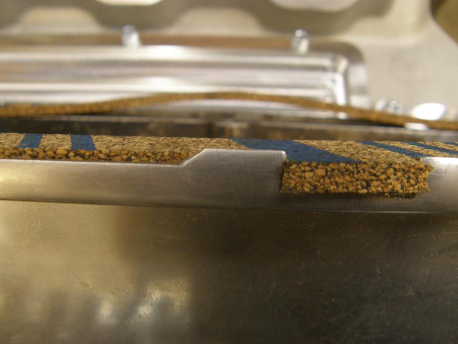
The tab sticks below the gasket, and when I tried to bolt on the covers the tabs kept them from seating all the way on the intake. The fix was to machine a little slot in the intake to allow clearance for this tab, as shown in the photo below:
But now I'm wondering whether I shouldn't machine that slot along the entire valve cover rail, rather than just where the tabs on the CJ valve covers are. I kind of hate to do that because I wanted to leave as much room above each port in the casting as possible, to allow the port to be raised if necessary, but at the same time I have no idea if some of the other covers out there have these tabs, and if they are in different locations. I wouldn't want to had someone try to bolt on a pair of valve covers and not have them seal correctly. Right now I'm leaning towards machining the slot the whole way just to eliminate potential valve cover clearance problems. Any comments on that?
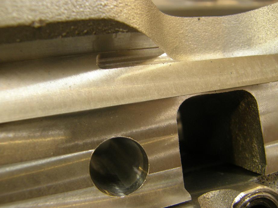
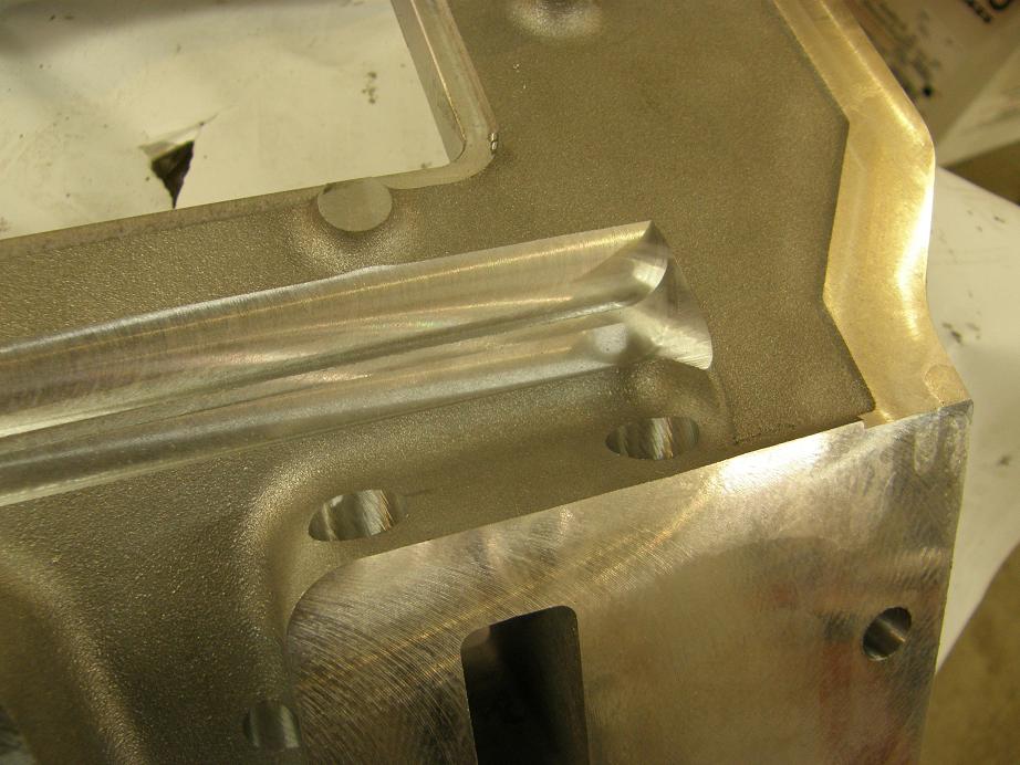
I also ran across a problem with getting my Crower roller lifters in and out of the lifter bores with the manifold installed. I had discovered this problem on the first manifold, and had made some changes to clear away some material under the manifold to address this issue, but first time through on the second manifold I hadn't removed enough material, so the roller lifters still could not be installed; the tie bar assembly got in the way. I made a modification to the program and took off some more material, and finally then everything worked. Here's a photo of the underside of the manifold, showing the stepped machined surface. The step that took more material off the manifold is what was required to make sure that the lifters could be replaced with the manifold installed:
I tried the Crower roller lifters in all positions, and could get them into place without much trouble, so I'm satisfied at least that the Crowers can be removed and replaced with the intake adapter installed. However, it is not clear to me that other brands of roller lifters will be able to be removed with the manifold in place; I'm going to have to do some test fitting on the manifold to find out. I think I have a set of Comp Cams roller lifters for the FE here, and I'll give those a try. Flat tappet lifters are no problem to remove, of course, but the roller lifters with their tie bars can have a clearance problem.
After getting the manifold installed on the test engine I also reassembled the valve train to check the pushrod hole location, and everything looks pretty good there. Right now the pushrod holes are 5/8" diameter holes, but I was thinking about elongating them, making them oblong, to give more clearance towards the rocker arm and towards the manifold. The downside of this is that if I did that, they would be difficult to sleeve. With the round hole, if someone was porting one of these manifolds and broke into the pushrod hole, they could just seal it up by sleeving the hole with a thinwall 5/8" OD brass tube. However, if I made the hole oblong, then sleeving it would be a much more difficult proposition. There'd be lots more pushrod clearance with an oblong hole, though. Any thoughts on the tradeoffs there?
Finally, today when I was installing the cam and lifters with the manifold in place I couldn't help but think about how much easier it would be to change cams with a two piece timing cover. I've been thinking about this as a follow on project to this intake manifold. At the risk of having Bob (machoneman) call me "Pro-Stock Paul" again, do you guys think I should pursue a project like that? With the two piece timing cover you would still have to pull the valve covers and valvetrain, and distributor, to get the cam out. You would also have to break the water jacket when you took off the water pump. But you wouldn't have to break the intake free and reseal it, and you wouldn't have to pull the harmonic balancer to get the timing cover off, you could just pull an access plate (that would seal with an O-ring) to get at the top timing gear and cam. Thoughts, good or bad, on this?
I keep thinking I'm almost done with this thing, but it keeps dragging on just a little longer. Maybe next weekend...


