It has been quite the CNC weekend here, but this lump of aluminum is finally starting to look like an FE intake. I spent most of the day Saturday and all day today writing the programs and running them very carefully with the CNC machine, to try to catch any major mistakes before they happened. After writing the first programs yesterday afternoon, I set up to run the code and the very first thing that happened was I had a typo in the code, and didn't catch it until my 1" end mill just about bored through the rear end rail of the manifold

It was on a rapid downstroke of the tool and even though I had my finger on the Feed Hold button of the mill, I couldn't stop it in time. Just a cosmetic problem, but still... Then, a couple of operations later the same thing happened again, this time with a 1/2" end mill. Damn typos...
Despite these issues I made progress all day yesterday and today on the intake. I was going to put together a video of the manifold turning on the 4th axis, but I haven't had time to put that together yet. So here are some pictures. The first two pictures show the intake in the CNC machine:


Note on the second picture that the manifold has to be positioned directly under the carousel tool changer for some of the operations. Towards the back of the tool changer you can see a 1 1/4" roughing end mill, along with some fairly long drill bits. Those got in the way during various operations while I was machining the manifold. Fortunately I didn't crash the manifold into any of the tools, but several times I had to stop, reposition the tools in the carousel, and then re-write some code to allow for the change in tool position. There's a couple of operations where the manifold just barely sneaks between two of the tools that are hanging down, but as long as it doesn't hit them, there's no problem. The issue isn't relegate to the manifold hitting the tools, either; when the manifold is positioned upside down the trunnion table tends to get in the way. See the photo below:

Despite all this, and some other minor machining errors, I was able to get the manifold largely machined this weekend. In order to finish the head and 351C manifold surfaces of the intake I need a facing mill, and I don't have that yet; I should be getting it this week sometime. But by the end of the day today I wanted to test fit the intake on my mock-up engine, so I ended up machining the mating surfaces with a 1" end mill, and leaving .062" of extra material on each surface. That is the exact thickness of a gasket, so I figured I would test fit the manifold on the engine with no gaskets in place.
I finally got all the required machining operations done earlier this evening, and took the manifold off the fixture. Here's a couple photos of it sitting on the engine:


It fits beautifully! Even the distributor dropped right in, and I have that hole tightly toleranced at the moment so I can move it around if necessary. I can't tell you how happy I was when I measured the height of the valve cover rails and found them all to be within .002" of the height of the rails on the head. I had been worried that there would be some major issue with fit, but thankfully those worries proved unfounded. I told my wife that I felt like I'd given birth, but she just shook her head and walked away

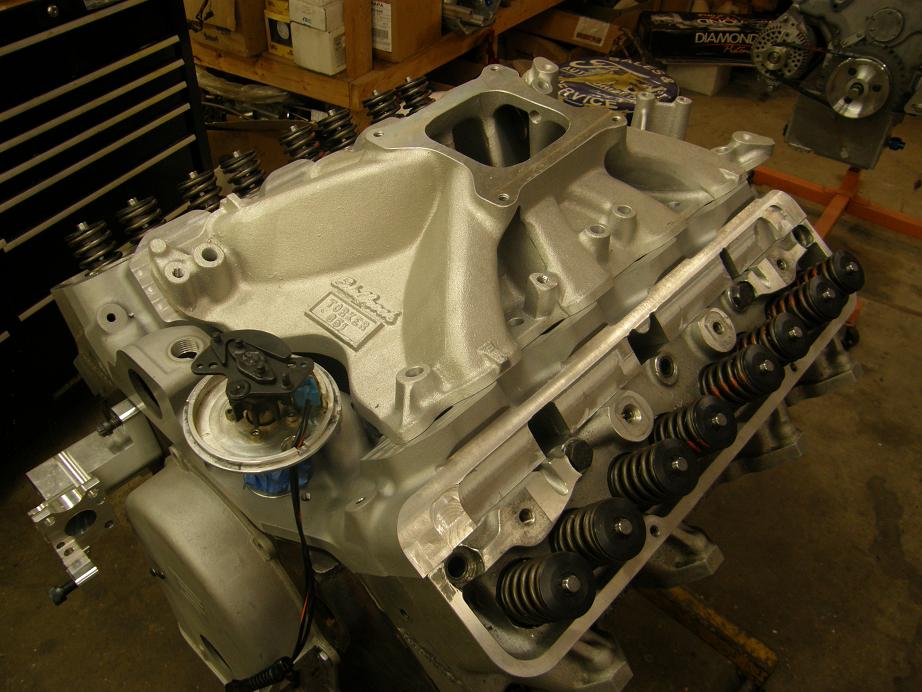
Just for grins I dropped a few of the 351C manifolds I have here onto the adapter to see how they looked. The first photo shows the Edelbrock Torker 2; you can see that the bottom of that manifold will have to be cut or machined in order to fit all the way forward, because the manifold base hits the water jacket passage of the intake adapter:
Next I put the Edelbrock 2991 351Y (Y is for Yates) intake on. This intake will require a slight modification to the machining of the intake adapter, because the ports are raised compared to a stock 351C port location. But there's plenty of room on the adapter for that. The intake will also require a different bolt pattern on the adapter; again, not a big deal.

Finally I stuck the big dog, the Edelbrock 2865 Glidden Victor, on the adapter. I know a guy who has made over 800 HP with this manifold on a big 351C, so it is definitely capable of running the numbers. But you can see from the photo that this manifold will require even more machining on the adapter, and probably on the flanges of the intake too, in order to fit.

For now I'm focusing on getting the machining operations completed for the intake adapter to mount the standard 351C manifolds. Next weekend I should get all the bolt holes and pushrod holes done, get all the flanges finish machined, and maybe start working on the ports. I'll post more pics as I get further along...


