The 69 Shelby clone project moved forward substantially this week, with what was essentially an extra day on the weekend to try to get some things done. Early in the week I was tied up with family activities, but on Tuesday my Currie axle housing finally arrived, so I was ready to move forward with getting the rear end tacked up and positioned under the car. I was disappointed when I called Discount Steel on Tuesday and they told me that they still didn't have the chrome moly roll cage tubing I had ordered, but they were fairly certain they would have it next week. And on Wednesday I picked up my case and gears from BradFORD, plus my Fatman Fabrications front strut conversion kit came, so between the rear end work and the Fatman kit I had plenty to do over the weekend.
Friday morning after Thanksgiving I got out to the shop to get started. I checked the overall length of the Currie axle housing and it seemed to be right on, so I bolted my jig case into the housing, and slid the 2 1/4" steel tube through the donuts in the case so that it was sticking out of both ends of the housing. Next I took the four link brackets and slid them onto the axle housing tubes; this had to be done now, because they wouldn't fit on over the housing ends. Then I took the Mark Williams housing ends and slid them over the steel tube with the donuts in place inside. They looked like they lined up perfectly with the axle housing, indicating everything was straight. Finally, I dug out my wire feed and tacked the housing ends into place.
I am always extremely cautious when welding on the rear end, because I want to be sure not to warp anything, so I basically put three button welds spaced 120 degrees apart on the housing end to axle housing joints. I welded one side first, and then the other, and then went back and forth with the button welds until I had a bead about an inch long in three places around each axle housing tube, tacking on the housing ends. I will finish weld this later, when I finish weld all the other components onto the axle housing, such as the back brace, four link brackets, rear sway bar brackets, etc.
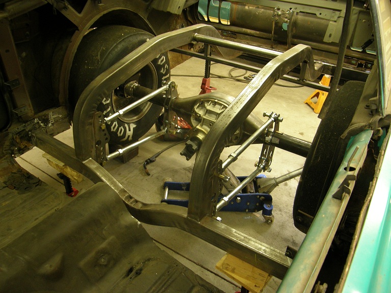
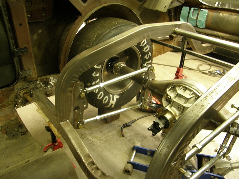
Next I removed the jig tube and the aluminum donuts in the housing ends, and unbolted the jig case from the axle housing. Then I bolted in the Mark Williams case, and installed the forty spline axles into the housing. Thankfully, they seemed to be the correct length and fit perfectly. Then I horsed the rear axle assembly up onto a floor jack, and rolled it around to the back of the car and positioned it underneath the back half frame rails.
Next step was to add the four link bars to position the axle housing correctly with respect to the back half frame. I assembled the rod ends on the four bars and made sure that each bar was exactly the same length, then bolted them into the brackets on the back half frame, and then onto the brackets that were on the axle housing. Finally, I screwed the drive studs into the axle flanges on each side, slipped on the Wilwood disc brake hats, and bolted on the wheels and tires.
As the wheels and tires went on it was clear that the back half frame was positioned too far to the rear of the car. I had a floor jack supporting the front of the back half frame crossmember, and jack stands supporting the rear, and another floor jack supporting the center of the rear axle housing. I moved the floor jacks together to get the tires positioned directly under the wheelwells, and then jacked up the rear axle housing to get the tires positioned up in the wheelwells like they would be with the car sitting normally.
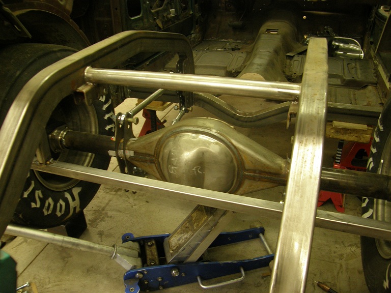
When I had the wheels and tires where I wanted them, and the four link setup assembled, I was finally able to position the back frame rails in the proper position side to side, and mark them so that I knew where to cut them off so that they would fit up into the trunk area and butt up against the 2X3 rectangular steel tube that I had already welded in place there. After marking I dropped the back half subframe off the jackstands in back, and cut the subframe rails off with a cutoff wheel in my grinder. Then I repositioned the back half subframe under the car, and moved it around until I had it in the final position. I cut the 1/8" steel plates to go against the rocker panels for the front crossmember to weld onto, and locked them in place with some vise grips. After double checking all the measurements to make sure that the back half subframe was straight and square in the car, I tacked it into place with the wire feed.
It was now getting towards the end of the day, but there was still one more thing I wanted to accomplish. I had purchased some 1" X 1" 16 gauge square steel tubing to kind of frame up the trunk area, and provide a reference for the tops of the trunk drop downs. I was able to add in this framework pretty quickly, again just tacking the pieces in place. Here are some photos of the back half subframe installed in the car:
On any car project there are milestones along the way, and this was certainly one of them for this car. I'd never installed a back half kit before (although I had built one from scratch, with help, back in the 1980s), and the installation hadn't been too difficult once I'd been able to clear out the back of the car to see where everything was going to go, and had all the pieces in hand for the mock-up of the rear frame in the car. I left the shop on Friday night feeling pretty good about how this project was shaping up.
Saturday morning I was anxious to get started on the front strut conversion. There was still a bunch of stock brackets and wiring in the engine compartment of the car, so I spent the morning pulling all that stuff out of there. The instructions for the kit suggested that I start with some of the smaller pieces, but I wanted to bolt the K member assembly in place and see how it fit, and how it looked. I was concerned about this because as unit body cars, the old Mustangs are notorious for imprecise assembly, and what fits one car may not fit another. Sure enough, as I got going on installing the K member this seemed to be the case with my car also. There was a lot of prying and convincing required to get the spacers that fit up into the lower control arm mounting brackets installed, and then more work was required to get the spacers installed outside the control arm mounting bracket and inside the brackets on the K member. Nevertheless after an hour or so of effort, I was able to get the K member installed, and the bolts in place through the lower control arm mounting holes.
At the front of the K member the kit provided two steel spacers, each of which extended from the K member up to the factory sway bar mount on each side, in order to provide some stability to the front of the K member. The spacers bolted into the K member through a slotted hole, probably provided to allow some adjustment and compensation for car to car variations in the chassis. But on my car even the most forward position in the slot would not allow the spacers to line up with the original sway bar bracket holes. So it looked like I would have to modify either the K member or the sway bar bracket hole to make the spacers fit. I decided to leave this task for later.
Next I thought I would concentrate on the steering. I had purchased a rebuilt power steering rack for a '94 Escort on ebay, and the instructions with the kit said the first thing I had to do was to remove the boots and take off the inner tie rod ends. I'd never done any work on a steering rack before, so this was going to be all new to me. The instructions said that after the boots were off to put a little heat from a propane torch onto the inner tie rod ends to loosen up the Loctite on the threads, and then unscrew the tie rod ends from the rack. However, after putting heat on the tie rod end for about 30 seconds, I started seeing some melted white plastic coming out of the end of the tie rod end. What the heck? It appeared that the tie rod end had some kind of a plastic liner around the ball, and that application of the heat had melted it!
Hmmmmm, they hadn't said anything about that in the instructions. Maybe not all of the tie rod ends had this, but mine sure did. I called BradFORD to see if he could shed any light on this. He told me that most of the rack inner tie rod ends he'd seen had this kind of a liner, and that applying heat was not necessary to remove the tie rod end. He thought that applying heat to the inner tie rod end was probably bad advice, but that I could get a replacement inner tie rod end, and they weren't too expensive. Great. I thanked Brad and went back to the rack. I put a wrench on the inner tie rod end that I had heated and with minimal effort it turned free and came off. Then I tried the other side that hadn't been heated, and it came off just as easily.
Figuring I could go out later to get a replacement tie rod end, I decided to proceed with the modification to the one that had come off with no heat. The instructions said to cut 4 1/2" off the threaded end of each tie rod end, and then rethread them with the die and die handle that had come with the kit. Easiest way for me to do this was to chuck the tie rod end up in the lathe, and cut and thread from there. This was kind of a time consuming operation, but it proceeded without any problems, except that the tie rod end I had taken off had a thicker cross section 4 1/2" back than it did at the original threads. So, in order to thread it, I also had to turn down the diameter a little bit to make the threads. This was no trouble for me, but I imagine that a guy in a shop with no lathe would have been hard pressed to complete this step. There was no mention of this issue in the instructions.
Next I looked at the next modification to the rack, which was to add some spacers at either end. On the passenger side there was a 4 3/4" long spacer that basically extended the rack. This screwed on in place of the original tie rod, and then the new tie rod was screwed onto the spacer. On the driver's side, there was a short spacer that also was a stop that screwed in place before the tie rod end was installed. Unfortunately, that short spacer appeared to be missing from the kit. I searched the box and all the bags that the components had come in, but no luck locating this piece. Finally I looked at the checklist of parts that was included with the kit. All the parts included in the kit had a check mark next them, but sure enough there was no check mark next to the spacer. So, it looked like I was stalled on re-assembling the rack.
So far the installation of the Fatman kit was not going well. I decided to try to install the rack on the K member, so that I could look at what would be required to adapt the rack to my factory steering column. The kit had come with two steering universal joints, one that was a straight DD to DD shaft u-joint, and a second one that was DD on one side and had the correct hole for the V-shaped input shaft coming out of the rack. The instructions said that the u-joint was a very tight fit on the rack, and boy they weren't kidding! I ended up taking a file to smooth the edges of the input shaft, and driving a wedge into the split in the u-joint before I finally was able to work the u-joint onto the rack's input shaft. But I got it in the end, and installed the bolt clamping the u-joint into place.
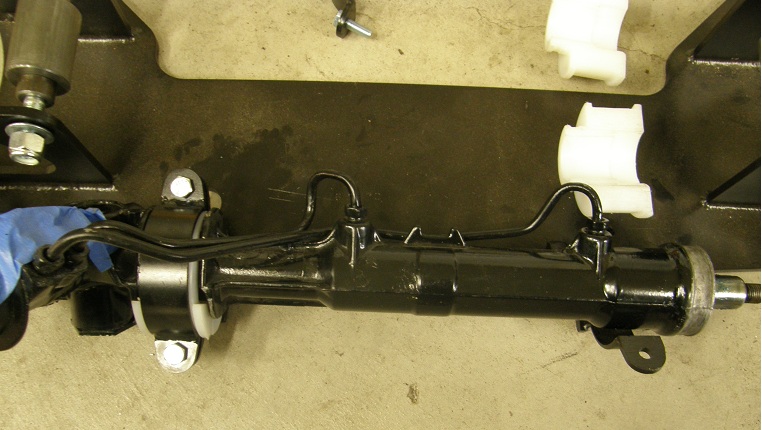
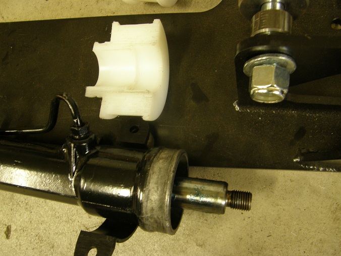
Next I went to bolt the rack onto the K member. The K member had two U-shaped brackets welded to it that the rack fit down into, bushed by a couple of large nylon bushings. The two nylon bushings were each split in half and fit around the rack, and then the assembly fit down into the U-shaped brackets. Two more U-shaped brackets were provided to clamp over the top of the brackets welded to the K member, to keep the rack in place.
Again with this assembly, I ran into problems. The split nylon bushings fit correctly around the driver's side of the rack, but on the passenger side, the nylon bushings weren't even close to fitting. At first I thought this was an access issue, so I pulled the K member back out of the car to fit the rack into it (it came out a lot easier than it went in). But it turned out to be the bushing. Here are a couple photos showing the rack and the associated U-shaped brackets on the K member, and the nylon bushings:
After this last disappointment, I called it a day in the shop. No way I was going to resolve the issue of the missing spacer and the incorrect rack bushing without calling the manufacturer, so I sure wasn't going to be able to get this setup installed over the weekend. I went in the house and adjusted the schedule on my spreadsheet to reflect this reality, and hoped for a better day on Sunday.
Sunday morning I ran off to Napa to get a replacement inner tie rod end. At the parts counter they offered me two different versions, the cheap lower quality one and the expensive higher quality one. I had them bring both of them to the counter so I could look at them. Sure enough, the more expensive one had a thicker shaft and would need to be turned down before threading after it was shortened 4 1/2" per the instructions. Obviously the kit had assumed that the cheaper tie rod ends were on the rack, or maybe the factory Ford tie rod ends also had the smaller diameter. In any case, since it was no problem for me to turn down the thicker tie rod end, and since I had already done that for the other side, I spent the extra $10 on the more expensive one. I also picked up the outer tie rod ends I needed for the steering linkage, which I had not yet acquired.
Back at home I repeated the process of cutting, turning down, and rethreading the new tie rod end, and then took the time to assemble the passenger side of the rack, since I had the extension that went on the rack on that side. With half the rack done I was now waiting for parts, so I decided to move on to the modifications to the '94-'04 Mustang spindles. This was fairly straightforward, involving cutting the steering arm off these spindles (which is not used by the kit), and then grinding the area at the bottom of the spindle where the ball joint stud comes through to allow for the required up and down control arm travel. This took me an hour or so, and then the spindles were ready to go.
Finally I reinstalled the K member (it went on easier this time), installed the lower control arms with the bolts loose, and put the spindles on the ball joints, just to get an idea of how the suspension was shaping up. Everything looked fine, but I am now officially stalled on the project, needing the chrome moly tubing in order to start the roll cage contruction, and the missing/correct parts from Fatman to continue with the front suspension work. We will see what the next week brings.


