Author Topic: Dyno Mule to Test 351C Intakes on the Intake Adapter, Carb and EFI  (Read 81860 times)

0 Members and 1 Guest are viewing this topic.

cjshaker

  • Hero Member
  • *****
  • Posts: 4461
    • View Profile
Re: Dyno Mule to Test 351C Intakes on the Intake Adapter, Carb and EFI
« Reply #45 on: June 05, 2017, 07:20:28 PM »
I figured that's what you meant, and wasn't trying to nit-pick, but to guys that don't wire stuff much, it may have been confusing. Like a light socket, you don't want it hot when the power is 'off'. In house wiring, it can be deadly. In car wiring, it just helps by avoiding shorts while working on something.
Doug Smith


'69 R-code Mach 1, 427 MR, 2x4, Jerico, 4.30 Locker
'70 F-350 390
'55 Ford Customline 2dr
'37 Ford Coupe

jayb

  • Administrator
  • Hero Member
  • *****
  • Posts: 7406
    • View Profile
    • FE Power
Re: Dyno Mule to Test 351C Intakes on the Intake Adapter, Carb and EFI
« Reply #46 on: June 06, 2017, 03:05:58 PM »
Today I got the engine running and dyno tested with the MS3-Pro running the MSD.  Before I go into how to do that, please note that one of the tables in my preceding post had a wrong entry; the Ignition Options table has been updated on that post to be correct.  You may have to refresh your browser window to see the change.

To get the timing set about where it needs to be to start, I like to turn the engine over without fuel while watching the timing light.  As mentioned previously in this thread, a fully degreed balancer, or a timing tape on a stock balancer, is invaluable.  Looking at the ignition options menu, on the left side you can see an entry labeled Cranking Advance.  This is the timing advance that the MS3-Pro commands when the engine is cranking over.  What we would like to see is this value when the timing light flashes.  Mine is set at 10 degrees BTDC.

First, the MSD Digital 6 can be set up for a 20 degree spark retard when cranking.  Mine was set up this way, so I disabled that feature by turning the screw on the side of the MSD (You set the cranking timing in the MS3-Pro, so there is no need for the spark retard from the MSD).  Turn on the ignition key, but don't pump the accelerator, or give the engine any fuel.  Crank the engine while using the timing light.  Again, you would like to see 10 degrees BTDC, but if you are like me you won't be close  ;D  Mine read something like 45 degrees BTDC.  You have already locked down the distributor so that the reluctor is properly phased with the pickup, so we won't twist the distributor.  Instead, we will go to the Ignition Options menu and change the value in the Trigger Angle Offset box.  Mine was originally set to 25 degrees.  I bumped it up to 45 and checked the timing with the timing light again.  For some reason, the degrees in the box don't match what you see with the timing light, so you can't expect to see a reduction of exactly 20 degrees, with a 20 degree change in the trigger angle.  I was reading something like 17 degrees BTDC at this point with the timing light.  Close enough to start, though.  I turned on the fuel pump and started the engine up.

Once started, what you want to do is put the engine in a spot where the timing commanded by the MS3-Pro is stable.  For my engine, one spot for that was between 1600 and 2000 RPM; at that speed, the timing table says that total timing has to be 25 degrees.  With the engine running, there is a marker on the timing table (and on every other table, for that matter) showing you where the engine is operating.  Here's a picture of the timing table that I captured with the engine running; you can see an oval right between 1600 and 2000 RPM, and at about 60 kPa.  This is where the engine was operating when I captured the picture:


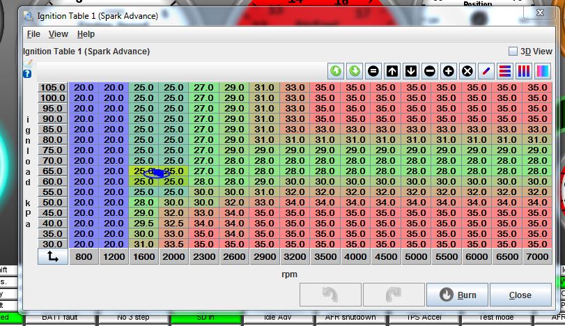
Also notice the little blue gob of color inside the oval.  This is actually a bunch of blue lines, that represent a track of where the engine has been for the last few seconds.

To finalize the timing, you should wait until the engine is warmed up, because there are some parameters in the software that will alter the timing for a cold engine.  So, I waited until the engine was at 150 degrees before making any adjustments.  Then I pulled up the Trigger Wizard menu in the MS3-Pro, which is under the Ignition Settings menu:


This screenshot was captured with the engine not running, but if you are at a stable point in the timing map, the timing that is being commanded by the timing table is in the big black Advance box.  Mine said 25 degrees at this point.  Next I put the timing light on the engine, and it read a little advanced, 30-something.  In the Ignition Offset angle box in the Trigger Wizard, I changed from 45 to 55, Burned the new setting, then checked again with the timing light.  In order to get it exactly at 25 degrees, I ended up with 58 degrees for the offset angle.  But that's all there is to it, now the engine is perfectly timed and we never had to touch the distributor!

One note of caution here, and that is that if you need to put a negative offset angle into the ignition offset box, the MS3-Pro won't be able to recognize it and save it with the software.  If you find yourself decreasing the angle to zero, and you are moving in the right direction but still not at the timing that the table is commanding, then you WILL have to twist the distributor to compensate.  Just twist it in the normal direction to increase or decrease timing advance and give yourself some more range, then lock it down again and go back to the Trigger Wizard to dial it in.

Now I was ready to run a dyno pull.  I ran a checkout pull from 3500 to 5000 RPM, and the engine sounded fine and made essentially the same power as it had before.  Then, I tried a 4500-6500 RPM pull, and was surprised to find that the engine fell flat on its face at about 5400 RPM.  This issue would end up frustrating me for a full day; I re-checked wiring, reviewed all the software settings, etc.  When I switched back to running just off the distributor and MSD, the engine returned to normal behavior, so I figured I had something wrong in the settings, maybe a rev limiter was coming on or something.  But everything seemed correct.  Finally, I tried swapping out MSD boxes, and what do you know, the engine ran great with the new MSD box.  The only thing I can conclude is that the points input on the one MSD Digital 6 doesn't work correctly.  In truth, I have never used the points input until this engine, and I've had the MSD for at least 10 years.  It works fine when triggering off the MSD distributor, but not when using the points wire.  Something wrong in the circuitry I guess, because the replacement MSD works fine.

So, now that I had that issue resolved I decided to do another dyno pull and get some data.  One of the big advantages of any good EFI system is datalogging.  For the MS3-Pro you can do this a couple of different ways, through the computer, or with an external button that starts and stops a datalog that records internally in the unit, and can be retrieved later.  Since I was on the computer already I just used that.  Under the Datalogging menu at the top of the screen, click on Start Logging.  A screen will come up asking you to name the log:


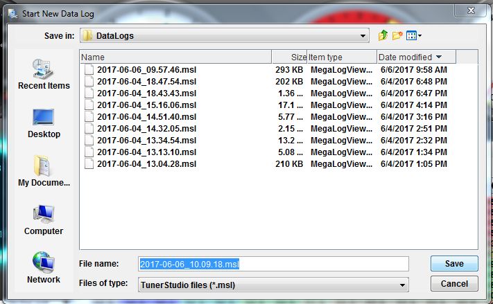
The default file name that comes up is time based; in the screen shot above, this is June 6, 2017, 10:09:18.  I usually just accept the default because it is convenient to have the datalogs in chronological order.  Click Save in the box, and the datalogging starts.

To stop the datalog you can either shut off the ignition, or click Stop under the Datalogging menu.  To view the datalog, open up the other piece of software that you downloaded earlier, Megalog viewer.  When this software opens up, go to File and then Open, and navigate to where your datalog file is.  If you accepted all the defaults when you set up the software, it will go right to the correct location.  When the datalog opens up,  it will look something like this:


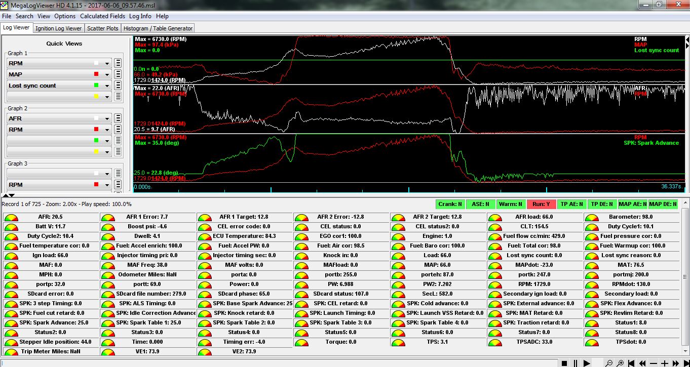
This is kind of a confusing screen, but its easy to simplify.  All the boxes at the bottom represent different parameters that are logged by the datalogger.  At the top, there are some default graphs that come up, showing various parameters.  Grab the top edge of the boxes showing the parameters and move it down so that you have more room for the graphs.  You can add more graphs, or delete them by removing all the parameters in them.  In the screen below I have made the graph area bigger, changed to one graph, and the graph shows RPM, Timing, MAP, and A/F from the O2 sensor:


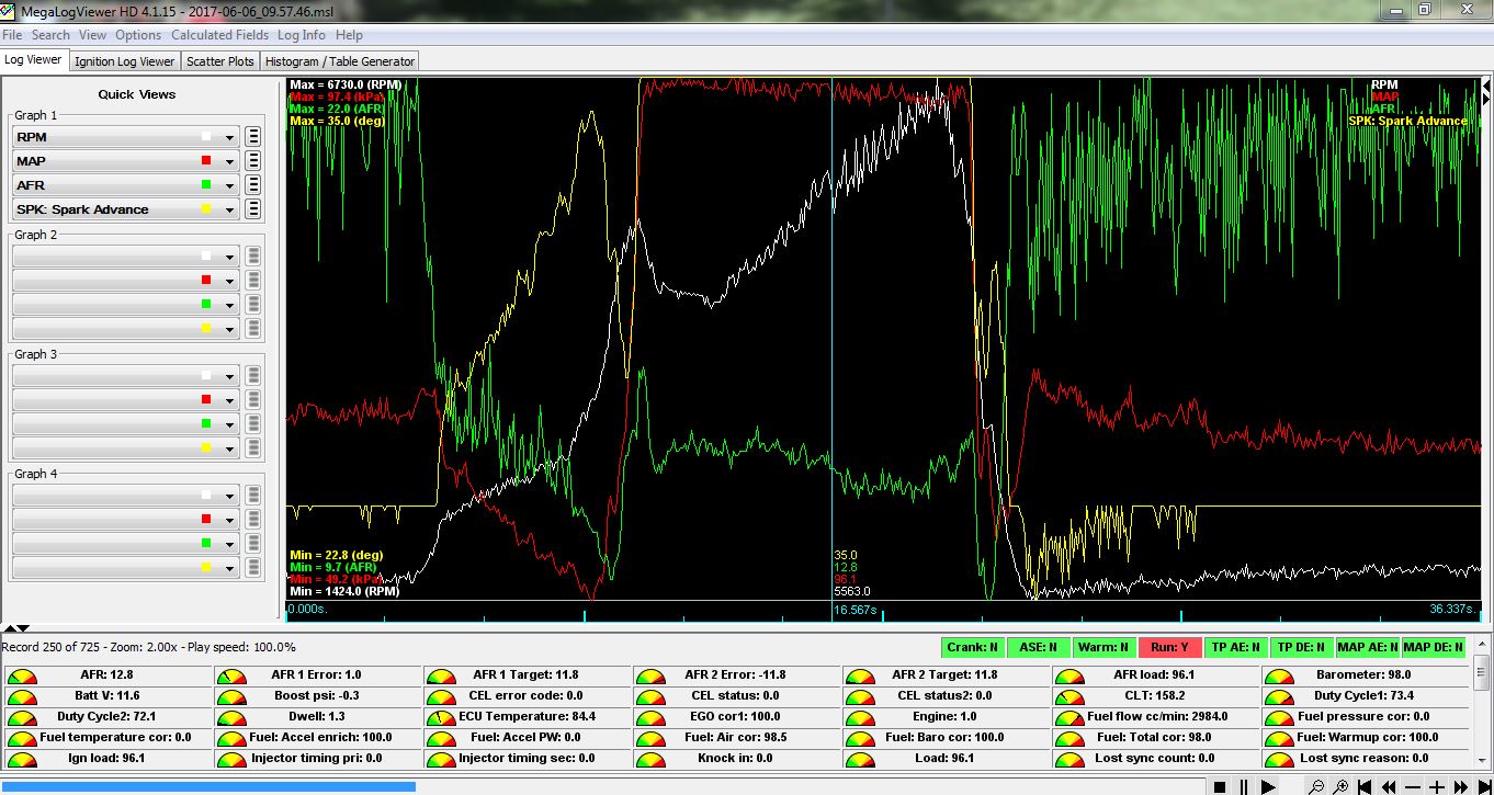
Notice the thin blue vertical line in the middle of the graph.  You can click anywhere in the graph to place that line, or move it left and right with the arrow keys.  Down at the bottom of the line are the numbers that represent the data.  The line is positioned in the middle of the dyno pull in this picture.  So, timing is peaked at 35 degrees, A/F is reading 12.8, MAP is 96.1kPa, which is very close to atmospheric pressure, and engine speed at this point is 5563 RPM.  Also, on the left side of the graph you will see minimum and maximum numbers recorded for all the parameters during the datalog.

A few other comments.  First, notice that before and after the pull, the A/F is reading very lean.  This is a function of the leaks in the dyno exhaust system; air gets into the exhaust and makes the O2 sensor think that the engine is running lean.  Another reason to be a little wary of O2 sensors; if your exhaust develops a leak, and you are relying on the O2 sensor to deliver the correct amount of fuel, you could be overfueling the engine.  Of course, during the pull, the reading looks pretty good.  This is because there is so much exhaust flowing that an air leak in the exhaust system makes very little difference.  This is why you can probably trust the O2 sensor in an open collector while you are going down the racetrack, but not on the return road or the pit lane.

Also, look at the RPM signal in this graph.  It is very, very noisy.  This is typical with distributor-based systems.  When we move this engine to the 36-1 toothed wheel, I expect a big improvement in the smoothness of the RPM signal.

So, how did the engine do with respect to power?  I was expecting no change, since triggering was still being controlled by the MSD distributor and spark by the MSD ignition box.  However, that's not how it came out.  The power and torque curves were a little smoother with the MS3-Pro, and torque was up, while horsepower was down.  In the graph below the red lines are the previous best pull, and the black lines are the pull with the MS3-Pro installed:


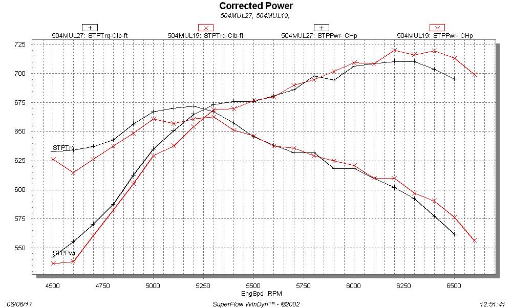
If I had to guess, I'd say that the reason that the curves were smoother is that the distributor is locked in this case; I noticed a lot of jumping around with the timing when running with the centrifugal advance in the distributor, but much less when it was locked and timing was controlled by the MS3-Pro.  The difference seen in horsepower and torque is anybody guess, but mine would be that the timing is not rock solid throughout the pull with the centrifugal advance distributor, so maybe variations in timing made the difference.

Also, one more comment about dyno curves.  Many dynos will add in a "smoothing" function to the data, and actually alter the data to make it look smoother than it really is.  This is not a good idea in my opinion, because if the raw data curve is not smooth, the engine is trying to tell you something.  All the dyno plots that I have posted, online and in my book, are raw curves, not smoothed.  In this case, you can see how much difference there is due to the change in ignition control.  This would not necessarily be obvious with a smoothed dyno curve.

Next test will be hooking up the crank and cam sensors, and running off the 36-1 toothed wheel.  It will be interesting to see how that plays out...
Jay Brown
- 1969 Mach 1, Drag Week 2005 Winner NA/BB, 511" FE (10.60s @ 129); Drag Week 2007 Runner-Up PA/BB, 490" Supercharged FE (9.35 @ 151)
- 1964 Ford Galaxie, Drag Week 2009 Winner Modified NA (9.50s @ 143), 585" SOHC
- 1969 Shelby Clone, Drag Week 2015 Winner Modified NA (Average 8.98 @ 149), 585" SOHC


Joey120373

  • Sr. Member
  • ****
  • Posts: 372
    • View Profile
Re: Dyno Mule to Test 351C Intakes on the Intake Adapter, Carb and EFI
« Reply #47 on: June 07, 2017, 04:39:01 PM »
Jay, have you tried using the "Fixed advance" feature pn the MS?
It's in the ignition options/wheel decoder screen on the top right.

This is what i usually use when setting up the trigger angle, it fixes the output at whatever you specify, say 10 degrees before TDC, and ignores the timing table and other timing modifiers all together ( no cold start advance etc ).

Then i do just like you did, adjust the offset angle till the timing light matches my fixed advance setting.

For me its a bit simpler to use because i don't have to worry about all the timing related corrections going on, its also very useful for diagnosing a poor running engine, you can just lock the timing to a set value, if the engine miss or stumble goes away, its a good bet some parameter it the timing set up is wrong, it the engine still doesn't run right, its a good bet its not related to the ignition timing.

Great write up, thanks for all your hard work.

jayb

  • Administrator
  • Hero Member
  • *****
  • Posts: 7406
    • View Profile
    • FE Power
Re: Dyno Mule to Test 351C Intakes on the Intake Adapter, Carb and EFI
« Reply #48 on: June 07, 2017, 04:59:27 PM »
That's a good suggestion, Joe, and I could easily have used that instead.  I just happened to have a fairly wide RPM band where the engine was stable, and timing was stable in that area too.  But setting the advance to fixed would have been really easy too.
Jay Brown
- 1969 Mach 1, Drag Week 2005 Winner NA/BB, 511" FE (10.60s @ 129); Drag Week 2007 Runner-Up PA/BB, 490" Supercharged FE (9.35 @ 151)
- 1964 Ford Galaxie, Drag Week 2009 Winner Modified NA (9.50s @ 143), 585" SOHC
- 1969 Shelby Clone, Drag Week 2015 Winner Modified NA (Average 8.98 @ 149), 585" SOHC


jayb

  • Administrator
  • Hero Member
  • *****
  • Posts: 7406
    • View Profile
    • FE Power
Re: Dyno Mule to Test 351C Intakes on the Intake Adapter, Carb and EFI
« Reply #49 on: June 12, 2017, 08:58:56 PM »
The next step along this path to EFI was to go away from the distributor pickup, and instead use the 36-1 toothed wheel to trigger the crank sensor.  As shown previously in this thread I have already set up the 36-1 wheel and the crank and cam sensors on the engine, so all that was necessary was to wire them up.  The ZF sensors I use are Hall effect sensors that require something called a pullup resistor.  Since these sensors are pretty popular, the MS3-Pro comes with the resistors that you need included with the EFI unit.  These are just small, 1K Ohm resistors that need to be wired in along with the sensors themselves.  Here's what they look like when they come in the MS3-Pro box:


Next, here is the wiring scheme for the sensors.  The sensors come with a European color code for the wiring.  Brown is for the power supply, 5 volts in this case, blue is for ground, and black is the output.  The 1K resistors need to be connected between the power supply wire and the output wire.  Since the resistors come already configured with wires, you can just crimp them together just like all the other connections, or solder them if you prefer.  A wiring diagram is below:


So, as shown in the diagram the brown wire connects to the 5V VREF wire from the MS3-Pro.  The blue wire connects to the Sensor Return wire from the MS3-Pro.  And the black wire connects to the CKP+ wire (white color) if you are wiring up the crank sensor, or the CMP+ wire (yellow color) if you are wiring up the cam sensor.  When I wired this today I decided to do both the crank and cam sensors, even though we aren't using the cam sensor yet since we are not installing the fully sequential EFI system yet. 

Once this wiring is complete, the distributor is now only distributing the spark from the coil; it no longer is being used to trigger the ignition.  So, the wires to the pickup of the distributor are now disconnected.

Now that we are using the 36-1 toothed wheel, we have to reconfigure the Ignitions Options in the software.  So, hook up the computer to the EFI box, and turn on the ignition switch, then pull down the Ignition Settings menu and go to Ignition Options.  The new settings in this menu should look like this:


Notice the Tooth #1 Angle (deg BTDC) box.  Way back at the beginning of this thread I set up the 36-1 wheel so that the first tooth after the gap (tooth #1) was about 90 degrees before TDC.  In this box I had originally written 90, not 97 as shown.  Changing to 97 was the adjustment I had to make in order to get the timing perfect, as explained below.

I decided to start the engine using Joe's suggestion, with Fixed Timing in the Fixed Advance box, instead of Use Table as shown in the picture above.  I also put 25.0 degrees in the Timing For Fixed Advance box just below.  However I was still using 10 degrees BTDC for cranking timing, so that's what I wanted to see on the timing light, before the engine started.  With the menus changed and burned into the MS3-Pro, I cranked the engine with no fuel and watched the timing light.  It looked like it was reading about 15 degrees BTDC, so I changed the Tooth #1 Angle to 95 degrees.  I repeated the cranking with the timing light and now I was pretty close to 10 degrees, so I added fuel and started the engine.  It started noticeably quicker with this ignition setup.  With the timing fixed I checked the light, and was a couple degrees off, so I changed the Tooth #1 Angle to 97 degrees to get the timing light to flash at exactly 25 degrees BTDC.  The timing looked rock solid with this setup, better than I had ever seen it before with the distributor, even with the locked distributor.  Last thing I did was to change the Fixed Advance box back to Use Table, instead of Fixed Timing.  Now the engine was running off the same timing table as it was with the previous setup.

I ran a dyno pull and the short story is that the engine didn't change much, except that the top end horsepower came back up.  But the major difference was that it just sounded a lot better.  This was reflected in the datalog from today's dyno pull, shown below:


Take a look at the white curve, which is the RPM signal from the sensor.  Look how smooth it is, compared to the RPM signal from the distributor pickup, reprinted below:


Quite a difference, and you can really hear it when the engine is running.  Its starts quicker and more easily, and it sounds cleaner through the pull, even though it is making about the same power as before.  That white line represents the speed of the signal being output to the MSD, which will then fire the coil.  It is more consistent, and less electrically "noisy", than the distributor setup.

Here's the data from the pull, with the most recent pull in black and the previous pull, where the MS3-Pro was getting its signal from the distributor pickup, in red:


Peak torque is identical at 671 lb-ft, and peak horsepower was up to 715.  Now it looks like the engine wants to rev higher too, although that last data point on the dyno plots can be deceiving.

Next, I will finish off this experiment by going to individual coil packs to fire the plugs.  I'm hoping that will make for a significant power increase, like the one I observed on my big SOHC;  we will see...
Jay Brown
- 1969 Mach 1, Drag Week 2005 Winner NA/BB, 511" FE (10.60s @ 129); Drag Week 2007 Runner-Up PA/BB, 490" Supercharged FE (9.35 @ 151)
- 1964 Ford Galaxie, Drag Week 2009 Winner Modified NA (9.50s @ 143), 585" SOHC
- 1969 Shelby Clone, Drag Week 2015 Winner Modified NA (Average 8.98 @ 149), 585" SOHC


jayb

  • Administrator
  • Hero Member
  • *****
  • Posts: 7406
    • View Profile
    • FE Power
Re: Dyno Mule to Test 351C Intakes on the Intake Adapter, Carb and EFI
« Reply #50 on: July 12, 2017, 06:50:56 PM »
Well, as usual I've been delayed a few times in getting back to this, but over the last few days I managed to convert the engine to full distributorless operation.  I started off last weekend by machining a new set of coil brackets, to mount the IGN-1A coil packs.  These are billet 6061 brackets with some basic lettering on them, which is customizable for each application:


Here's a shot of one of the brackets with the coils mounted, and a couple of separate coils:


In addition to the coils, you need the connectors, or "pigtails", that plug into the connector on each coil.  The connectors come with about four feet of wiring which makes it pretty easy to wire them up:


Each connector has five wires.  The red wire is for the 12V power supply, which should come through a relay with a fuse.  The coil relay should be wired up the same as the fuel pump relay; see the wiring diagram earlier in this thread.  The reason for this is that with the fuel pump wire from the MS3-Pro controlling the relay, the coils are not powered up immediately when power is applied.  This prevents a random spark from happening when the ignition switch is turned on, and a subsequent pop from the engine.

The yellow wire is the trigger wire for each coil.  There are eight wires from the gray connector of the MS3-Pro that drive these wires.  The MS3-Pro wires are all yellow also, but with different colored stripes and lettering to distinguish them.  They are labeled Spark Output A, Spark Output B, and so on up to Spark Output H.  They are connected to the coils in the firing order.  So, with the FE firing order of 1-5-4-2-6-3-7-8, Spark Output A connects to the coil on cylinder 1, Spark Output B connects to the coil on cylinder 5, Spark Output C connects to the coil on cylinder 4, etc. 

The three other wires from each coil are ground wires.  They are grounded to different places for noise reasons.  All three wires are black, but two of them have stripes, one green and one white.  All the solid black wires from the 8 coils can be connected together and then connected to the negative terminal of the battery, or to the engine block where the ground strap is connected if there is one.  The eight black wires with the green stripe can all be connected together, and then connected to one of the cylinder heads.  And finally the eight black wires with the white stripe can all be connected together, and then connected to the same location as the MS3-Pro ground.

I wired these up one coil bracket at a time, by hooking the ground wires together on one side of a crimp connector and adding a few feet of #12 wire to the other side, so that I had three #12 ground wires coming from each coil bracket.  I did the same thing with the power wires, so that I had one #12 power wire coming from each coil bracket.  With the four yellow coil trigger wires that made 8 wires from each coil bracket.  Once this preliminary wiring was done, I fabricated a couple of small aluminum brackets for each side to hold the coil brackets, and mounted them in place.  Normally I'd have mounted the coil brackets somewhere on the intake, inboard of the valve covers, but since I'm planning to do a bunch of intake manifold testing on this engine, to minimize disruptions I decided to mount the coil brackets to the header bolts.  After the brackets were mounted I cut a new set of plug wires.  Here's a few pictures of the coil brackets mounted on the engine:


So, now there was no need for the distributor, so I pulled it out.  However, there still had to be a mechanism to turn the oil pump.  When I did the first distributorless FE for my high riser several years back, I figured out a way to cut down a distributor to a stub and drive the oil pump that way.  This is helpful for me on this project because I want to be able to test intake manifolds that have not been modified to work with the intake adapter, and the distributor gets in the way of some of these intakes.

The pictures below show one of my stub distributors.  This particular one was modified from an MSD distributor:


To make this unit I cut off the distributor above the rubber seal area, then counterbored it in my lathe to accept a bearing with the same ID as the distributor shaft (1/2", I think).  The distributor shaft itself was cut off to a length so that it would protrude through the bearing.  Then I machined a simple cap for the unit and drilled and tapped the modified distributor housing so that I could screw the cap to the top.  A little RTV for seal, and Voila!  A stub distributor for driving the oil pump.  Here's a picture of it installed in the engine; I used the original hold down clamp, but spaced it up a bit with a spacer so it would clamp the stub distributor.  Of course, it can be installed anywhere, since it no longer has any influence on the timing of the engine:


Finally I finished up the wiring by connecting the yellow coil trigger wires to the wires coming from the MS3-Pro, the 12V power wire to the coil relay as described earlier, and the ground wires to their respective places.  I connected the power and ground wires from the two sides together on one side of a crimp connector, then ran a wire from the other side of each crimp connector to its final destination.

Now that everything was wired up into place, I went into the software to configure it for the individual coil packs.  All the changes are on the Ignition Options screen.  Here's what it should look like when it is properly configured:


Here's what changed on the left side of the screen:

Spark Output:  Going High
Number of Coils:  Coil on Plug
Spark Hardware in Use:  Spark

And on the right side:

Dwell type:  Standard Dwell
Nominal Dwell (ms):  3.0
Spark Duration (ms):  2.9

Naturally, when I first made the changes I forgot to make the changes on the right side of the screen.  This left the Dwell type as Fixed Dwell, and I had the duty cycle set for 50%.  When I tried to start the engine with this setup, it would cough once and quit.  Investigating, I found that the coil fuse had burned up.  I assumed of course that I had screwed up the wiring, or had a short inside my wiring box, or something like that.  I checked and re-checked, disconnected the coils one at a time looking for a bad one, etc.  I blew about six fuses trying to chase this down.  Finally, I went back to the Ignition Options screen and discovered my mistake; with all that dwell the coils were trying to draw a whole bunch of current at once, blowing the fuse.  Once I had the dwell set correctly, the engine fired right up.

So, I was looking forward to the results on this setup, to see if it made a big difference in power like it had on my SOHC.  Short story is that it showed an improvement, but not a dramatic one.  Horsepower peaked at 723, and torque at 675, which are the highest values I've seen with this engine.  But there was no 20 HP jump or anything.  Here's a dyno plot showing the difference between this setup and the last one, where the distributor was still distributing the MSD's spark to the plugs:


And here's the latest pull compared to the original best pull with the distributor and MSD only, with no MS3-Pro involvement.


Just a guess, but I'd say that somewhere in the 800 to 900 HP range, the improvement due to the individual coil packs starts to make a more significant difference.  Or, the added power I got from my SOHC with the conversion was a fluke  ;D

Now that I'm finished with all this testing, I will start with the intake comparison testing on the 351C intakes that I have on hand.  I should have some results to post this weekend - Jay
« Last Edit: July 12, 2017, 06:56:00 PM by jayb »
Jay Brown
- 1969 Mach 1, Drag Week 2005 Winner NA/BB, 511" FE (10.60s @ 129); Drag Week 2007 Runner-Up PA/BB, 490" Supercharged FE (9.35 @ 151)
- 1964 Ford Galaxie, Drag Week 2009 Winner Modified NA (9.50s @ 143), 585" SOHC
- 1969 Shelby Clone, Drag Week 2015 Winner Modified NA (Average 8.98 @ 149), 585" SOHC


Heo

  • Hero Member
  • *****
  • Posts: 3288
    • View Profile
Re: Dyno Mule to Test 351C Intakes on the Intake Adapter, Carb and EFI
« Reply #51 on: July 12, 2017, 07:23:33 PM »
What you have there is basicaly a Model-T ignition :o with more refined control  you dont need
a spark lever on the stearing column and the coils is not made of wood ;D
One coil for each cyl fed with battery or Mag. current from a Comutator on the camshaft, coils with a built in "relay".
As long as they get current the relay opens and close and coil produce spark .
If you turn ignition on and one cyl is at ignition point it often starts the engine


The defenition of a Gentleman, is a man that can play the accordion.But dont do it

Barry_R

  • Hero Member
  • *****
  • Posts: 1916
    • View Profile
    • Survival Motorsports
Re: Dyno Mule to Test 351C Intakes on the Intake Adapter, Carb and EFI
« Reply #52 on: July 12, 2017, 08:47:56 PM »
Couple things to add.  Really targeted to the guys without a lot of EFI experience who are following along.

One is that when I have used distributor triggering on EFI I have found that the easy to do advance lock out feature on MSD or Mallory stuff still sometimes leaves some "wobble" in the distributor.  I use the "hot glue gun" to make certain that locked out remains locked out.

Other is that the FAST system I am used to has a similar fixed timing enable function to check against a timing light.  The FAST stuff has the ability to use variable timing to smooth out idle by adding or dropping a couple degrees to minimize RPM changes.  The fixed timing function knocks out all the variables and controls to give you a single clean reference point.  Not sure if that applies to the MegaSquirt or not - but it's worth considering. 

I also see any timing chain slop as wandering timing light under no load - but as you wind it up the timing seems fine.  It will mess with you if setting timing at idle and find inconsistent readings at higher RPM.

If you make that distributor stub cover teardrop shaped you can have it bolt right down onto the hold down position - eliminating the need for a clamp.  Easy to do and cleans things up a little.

My427stang

  • Hero Member
  • *****
  • Posts: 3934
    • View Profile
Re: Dyno Mule to Test 351C Intakes on the Intake Adapter, Carb and EFI
« Reply #53 on: July 13, 2017, 06:07:58 AM »
Very interesting stuff Jay, I am not surprised with the cleaner curve doing what you did, but when plotted it certainly hits home, especially with power gains across the entire curve.  Well done and well presented.  I am going to consider MS for my next one, I haven't used that software, it looks pretty intuitive and effective.

The dwell adjustment must have been a hair puller.  Can you answer a few questions?

1 - I reread it a couple times, but just to be clear, you tested - standard distributor w/ MSD, then trigger wheel with distributor, then coil on plug and trigger wheel?  I likely misunderstood it.  With MS3 Pro, do you eliminate the MSD?

2 - If I understood that correctly, can an MSD feed a distributorless ignition for low speed multi-spark?

3 - Did you experiment with any other dwell and duration or is that a calculated value based on the coils?

4 - Does MS3 Pro control injector timing based on the trigger wheel? I assume it used the skipped tooth and does it have input to adjust injector timing?  Only bringing this up for Drag Week driving because as soon as you are above idle the injectors are more of a fog than a timed event, but I have been making big gains in drivability with cam event adjusted injector timing, and with your man-sized injectors (LOL) and big cams it may be more beneficial. 

FYI, what I do in that case is for a desired injector duty cycle at high RPM, knowing cam timing events, I change rise and duration to stay within that duty cycle and volume but inject at valve opening.  You can do it with timing alone, but by manipulating the injector curve itself gets you a little farther, at least if you can control the injector.  I haven't seen it, but I understand some injectors don't like to be far off one slope.  The thought both of those controls is that it cleans up fuel falling out of suspension when there is less air charge movement at low rpm.

Ever the racer, your O2 sensor comment was clear.  This will sound like a poke back, but it's not, is it not possible to seal up a dyno exhaust?  You aren't the first person to tell me that and you certainly make a valid point on it being less of a factor (likely no factor) when volume is up especially with the air being moved by that engine, and I agree completely. and I am not sure if it really matters to you on the bottom of the curve.  I, of course, do not own, run, or even spend a significant time in a dyno, but what is leaky that close to the sensors?

« Last Edit: July 13, 2017, 06:15:43 AM by My427stang »
---------------------------------
Ross
Bullock's Power Service, LLC
- 70 Fastback Mustang, 489 cid FE, Victor, SEFI, Erson SFT cam, TKO-600 5 speed, 4.11 9 inch.
- 71 F100 shortbed 4x4, 461 cid FE, headers, Victor Pro-flo EFI, Comp Custom HFT cam, 3.50 9 inch

machoneman

  • Hero Member
  • *****
  • Posts: 3854
    • View Profile
Re: Dyno Mule to Test 351C Intakes on the Intake Adapter, Carb and EFI
« Reply #54 on: July 13, 2017, 06:36:19 AM »
Very cool Jay!

I wonder if you can now just list the "C" intakes you plan to run.

The Parker Funneleweb, among other mainly Aussie tall intakes like the AFD units, look to be real killers, but I don't know if you have access to them. Wish I had a intake to send you!

http://www.ausfordparts.com/FW4V.html
Bob Maag

ToddK

  • Sr. Member
  • ****
  • Posts: 437
    • View Profile
Re: Dyno Mule to Test 351C Intakes on the Intake Adapter, Carb and EFI
« Reply #55 on: July 13, 2017, 07:58:17 AM »
The Parker Funneleweb, among other mainly Aussie tall intakes like the AFD units, look to be real killers, but I don't know if you have access to them. Wish I had a intake to send you!

I have a brand new Parker Funnelweb manifold sitting in my shed. Would cost a fair bit in shipping, but if you really want to test one......

jayb

  • Administrator
  • Hero Member
  • *****
  • Posts: 7406
    • View Profile
    • FE Power
Re: Dyno Mule to Test 351C Intakes on the Intake Adapter, Carb and EFI
« Reply #56 on: July 13, 2017, 09:27:32 AM »
I have a Funnel Web here to test guys, I should be able to get that one tested this weekend.
Jay Brown
- 1969 Mach 1, Drag Week 2005 Winner NA/BB, 511" FE (10.60s @ 129); Drag Week 2007 Runner-Up PA/BB, 490" Supercharged FE (9.35 @ 151)
- 1964 Ford Galaxie, Drag Week 2009 Winner Modified NA (9.50s @ 143), 585" SOHC
- 1969 Shelby Clone, Drag Week 2015 Winner Modified NA (Average 8.98 @ 149), 585" SOHC


machoneman

  • Hero Member
  • *****
  • Posts: 3854
    • View Profile
Re: Dyno Mule to Test 351C Intakes on the Intake Adapter, Carb and EFI
« Reply #57 on: July 13, 2017, 09:42:27 AM »
Yeah! My money is on this one to win, save for a dual carb tunnel ram!
Bob Maag

jayb

  • Administrator
  • Hero Member
  • *****
  • Posts: 7406
    • View Profile
    • FE Power
Re: Dyno Mule to Test 351C Intakes on the Intake Adapter, Carb and EFI
« Reply #58 on: July 13, 2017, 10:00:39 AM »
Very interesting stuff Jay, I am not surprised with the cleaner curve doing what you did, but when plotted it certainly hits home, especially with power gains across the entire curve.  Well done and well presented.  I am going to consider MS for my next one, I haven't used that software, it looks pretty intuitive and effective.

The dwell adjustment must have been a hair puller.  Can you answer a few questions?

1 - I reread it a couple times, but just to be clear, you tested - standard distributor w/ MSD, then trigger wheel with distributor, then coil on plug and trigger wheel?  I likely misunderstood it.  With MS3 Pro, do you eliminate the MSD?


Tests were as follows:

1.  MSD Digital 6 and MSD 8594 distributor with mechanical advance, HVC2 coil, no EFI system involved.
2.  MSD 8594 distributor, advance locked and feeding into the MS3-Pro, using the MSD pickup in the distributor as the timing input to the MS3-Pro, and using the timing table in the MS3-Pro to control timing.  The MS3-Pro was configured to drive the MSD Digital 6, which provided the input to the HVC2 coil.  Spark then went to the distributor.
3.  Next I added 36-1 toothed wheel with crank sensor, and also added the cam sensor, and used the crank sensor as the timing input to the MS3-Pro.  The MS3-Pro output was configured as before, to trigger the MSD Digital 6, which drove the HVC2 coil.  With this test there was no timing input coming from the distributor, it was only being used to distribute the sparks from the coil.
4.  Last test was to totally removed the MSD distributor and MSD Digital 6 ignition, and replace them with coil packs driven by the MS3-Pro.  No distributor or MSD ignition box was required with this setup.

Quote

2 - If I understood that correctly, can an MSD feed a distributorless ignition for low speed multi-spark?


That's correct Ross, in scenarios 2 and 3 above the MSD Digital 6 is providing the multiple sparks at low engine speeds.  By the way, do you know what the spark duration is for an MSD ignition box at low speeds?  In their literature the individual coil packs claim that the spark duration they provide is much longer than a CD ignition box; seems that they are claiming due to the spark duration (2.9ms) there is no need for multiple sparks.  I always wanted to know how long the MSD sparks lasted, and how many of them there were, to try to compare with that 2.9ms number.

Edit:  Hmmm, rethinking this is is not really distributorless, since the MSD is firing the coil and the distributor is still distributing the sparks.  But in scenario 3 above the distributor does not control timing, the crank trigger does.  Is that what you meant?  As far as I know you couldn't go completely distributorless and still use the MSD.

Quote

3 - Did you experiment with any other dwell and duration or is that a calculated value based on the coils?


I didn't experiment with the dwell numbers.  I know from my blown fuse episode that too much dwell will cause the coils to draw too much power.  Scott Clark, who is a friend of mine and an EFI tuner extraordinaire, set the dwell for my big SOHC at 3ms, so I just used that for this engine too.  The 2.9ms spark duration came from the IGN-1A coil information.

Quote

4 - Does MS3 Pro control injector timing based on the trigger wheel? I assume it used the skipped tooth and does it have input to adjust injector timing?  Only bringing this up for Drag Week driving because as soon as you are above idle the injectors are more of a fog than a timed event, but I have been making big gains in drivability with cam event adjusted injector timing, and with your man-sized injectors (LOL) and big cams it may be more beneficial. 


Yes, the injector timing is controlled via the trigger wheel, and it can be adjusted a couple of different ways.  There is a global adjustment that will put each injector pulse at some point in that cylinder's cycle, for example 360 degrees before TDC on the firing stroke, and there are also individual cylinder trims, so that each cylinder can be adjusted from this global adjustment individualy.  Same with cylinder timing and the VE map, by the way, you can basically tune each cylinder individually for any parameter.

Quote

FYI, what I do in that case is for a desired injector duty cycle at high RPM, knowing cam timing events, I change rise and duration to stay within that duty cycle and volume but inject at valve opening.  You can do it with timing alone, but by manipulating the injector curve itself gets you a little farther, at least if you can control the injector.  I haven't seen it, but I understand some injectors don't like to be far off one slope.  The thought both of those controls is that it cleans up fuel falling out of suspension when there is less air charge movement at low rpm.

Ever the racer, your O2 sensor comment was clear.  This will sound like a poke back, but it's not, is it not possible to seal up a dyno exhaust?  You aren't the first person to tell me that and you certainly make a valid point on it being less of a factor (likely no factor) when volume is up especially with the air being moved by that engine, and I agree completely. and I am not sure if it really matters to you on the bottom of the curve.  I, of course, do not own, run, or even spend a significant time in a dyno, but what is leaky that close to the sensors?

It would certainly be possible to seal up the exhaust on the dyno, but probably not practical.  For example, there is a hole in each header primary where I install a thermocouple to monitor exhaust temperature.  The thermocouples kind of just lay in the holes, they are not particularly well sealed.  Then, to adapt the collector to the dyno's exhaust system there are a series of pipe to pipe adapters, going from the collector diameter up to the 6" diameter of the flexible stainless steel tubes that exit the dyno cell.  The pipe adapters tend to leak, and there is certainly not a perfect seal between the last one and the stainless steel flexible tube.

If you wanted to run without the thermocouples, and do a dedicated exhaust for just one engine out to the dyno exhaust, you could seal it all up.  But because engines come on and off the dyno, its not really practical to do that.  Funny thing about A/F on the dyno is that the dyno's A/F measurement, which relies on the air turbines and fuel turbines, is not very accurate at low engine speeds either.  So, until I get into a dyno pull, I can't really trust any of the A/F numbers that the dyno is providing. 
« Last Edit: July 13, 2017, 12:16:21 PM by jayb »
Jay Brown
- 1969 Mach 1, Drag Week 2005 Winner NA/BB, 511" FE (10.60s @ 129); Drag Week 2007 Runner-Up PA/BB, 490" Supercharged FE (9.35 @ 151)
- 1964 Ford Galaxie, Drag Week 2009 Winner Modified NA (9.50s @ 143), 585" SOHC
- 1969 Shelby Clone, Drag Week 2015 Winner Modified NA (Average 8.98 @ 149), 585" SOHC


fekbmax

  • Hero Member
  • *****
  • Posts: 1459
    • View Profile
Re: Dyno Mule to Test 351C Intakes on the Intake Adapter, Carb and EFI
« Reply #59 on: July 13, 2017, 10:36:43 PM »
Can't wait to see some of the results from the adapter/manifold testing.
Keith.  KB MAX Racing.