Author Topic: The Road to Drag Week 2016 - July 3, 2016  (Read 12094 times)

0 Members and 1 Guest are viewing this topic.

jayb

  • Administrator
  • Hero Member
  • *****
  • Posts: 7406
    • View Profile
    • FE Power
The Road to Drag Week 2016 - July 3, 2016
« on: July 03, 2016, 04:53:08 PM »
I wasn't planning on writing the weekly blog this year.  I had expected the run-up to Drag Week this year to be fairly sedate, with minimal changes to the car.  When I put the car away for the winter last November it was running fine, with no issues.  There were quite a few small updates that I wanted to do on the car, but I felt like if I had to I could have just changed the oil and gone off to another Drag Week. 

The car situation seemed like a good thing, because from a family perspective 2016 has been a very tough year so far.  My wife and my Dad were both beset by fairly serious illnesses and my mother-in-law passed away.  Our neighbor down the street, whose family took care of our kids every day after school for several years while my wife and I were working, suddenly dropped dead of a heart attack; he was one day older than me.  The dog got sick and nearly died, the cat was hit and killed by a car; this kind of stuff has just seemed to go on and on since the beginning of the year.  On top of that my regular job has been a real challenge this year and has been causing me fits, and it has taken much longer than I expected to get my high riser and tunnel port intake adapter machining programs finished and working.  Plus some of the new FE Power products have been delayed, notably the timing gear sets.  I just haven’t had any time to think about Drag Week.

Finally, a couple of weeks ago after getting my tunnel port intake adapter CNC programs finished and working, I decided I’d better start working on the Shelby clone.  I had a short list of updates I wanted to do, including finishing the work on the fiberglass bumpers so that they could be installed, installing a new EFI system with some updated wiring, and also putting some stops on the K-member that bolts under the car and holds the steering rack.  You may recall from last year’s Drag Week blog that the steering rack is not securely mounted on the Fatman Fab K-member (one of the many issues I have had with this kit).  I had problems during the event where the rack moved, and then the steering wheel angle changed and the car would pull to one side.  During the event I resolved the problem by hammering on the steering rack to put it back in position.  After Drag Week I was driving around my local area and had the same thing happen, so I wanted to drop the K-member and front suspension out of the car to try to fix this problem.  I figured that welding some fabricated screw jacks on the K-member to contact the rack and hold it in place would solve the problem.

So, two weekends ago I dropped the K-member and front suspension out of the car.  This left the bottom of the engine completely exposed, so I changed plans and decided to drop the pan and check the rod bearings.  With a 4.6” stroke and running up to 7700 RPM, the rod bearings were always going to be a concern.  I had been counting on the dry sump system to keep the bearings in good shape.  I pulled the pan and the second pair of rods were straight down, so I pulled the #2 and #6 rod bearings first.  They looked perfect, nearly unused!  The coating was still on the complete bearing, no sign of it wearing off.  I went ahead and replaced them anyway, but I probably could have just left them in there.  I put the wrench on the front crank bolt and rotated it 90 degrees so that #1 and #5 were at the bottom.  On #1 there was a scratch in the lower bearing shell, and there was a small area where the coating was nearly gone on the upper, but otherwise both sets of rod bearings looked beautiful.  I replaced both sets.

Then, something very unexpected happened.  As I rotated the crank another 90 degrees to get to the #3 and #7 rod bearings, I heard a big whoosh.  What the heck was that?  I looked towards the back of the car, and coolant was pouring out of the right side header tube!  Oh no…

I got out from under the car and sat down to think for a while.  The car had been sitting since November with coolant in it; I hadn’t drained it at the end of the year.  It had been running fine up to that point.  The garage is heated, and there was plenty of anti-freeze in the coolant, so it wasn’t possible that it had frozen.  Based on the position of the pistons when I turned the crank the last time, I figured that the coolant had come from the #2 cylinder.  Because of the spread bore spacing, I have to use custom copper head gaskets on this engine.  After some consideration I figured that I’d probably had a minor head gasket leak, and coolant had been seeping into the #2 cylinder all winter.  When I turned the crank, that cylinder must have been on the overlap stroke and all the coolant came out through the exhaust valve.

Well, this certainly shed a different light on the work I had ahead of me.  If I was going to put head gaskets on the engine it was going to have to come out; I wasn’t going to disassemble and re-assemble the SOHC while it was in the car.  But at least with the engine out and torn down I could get a really good look at the internal components to see how they fared over 2000+ miles of street driving and a bunch of trips down the race track. 

I crawled back under the car to finish looking at the rod bearings.  The #3, #4,  and #7 bearings looked perfect, but I did find an issue with the rod bearings on #8.  Both #8 bearing shells had lost their crush, indicating that they had gotten hot.  Also, on the upper bearing there was a spot near the edge where the coating was worn away and the bearing material looked like it was cracked or flaking.  See the photo of the #8 upper bearing shell below:


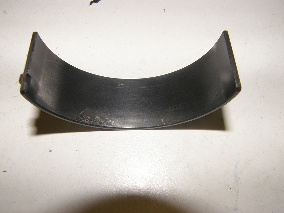
 I’ve seen this before and this has been explained to me as evidence of extreme heat.  Later that day I spoke with Blair P about this and he pointed out that the #8 rod gets its oil from the #5 main.  He had me look up the clearances on the engine (I record these on a build sheet whenever I build an engine), and while main bearing clearances on the #1 through #4 mains were in the 0.0023” to 0.0027” range, clearance on #5 was 0.0032”.  So that additional clearance on #5 may have contributed to this problem.

Later on that weekend while I was thinking about this some more, I realized with the engine out I could potentially address the issues in the #4 cylinder bore.  Last summer when I damaged the engine on the dyno I had installed a new piston and rod in #4, put a quick hone on the cylinder, and run it.  The hone had shown that there were two minor dings and a scratch in the cylinder bore.  These were down about 1.5” from the top of the bore, and not very deep, so I had just run with them in there.  But with the heads off the engine I could measure how deep those dings really were, and maybe hone the bore a little oversize and go to an oversize piston on that bore.  So, maybe pulling the motor apart wasn’t such a bad thing if I could fix this minor issue.

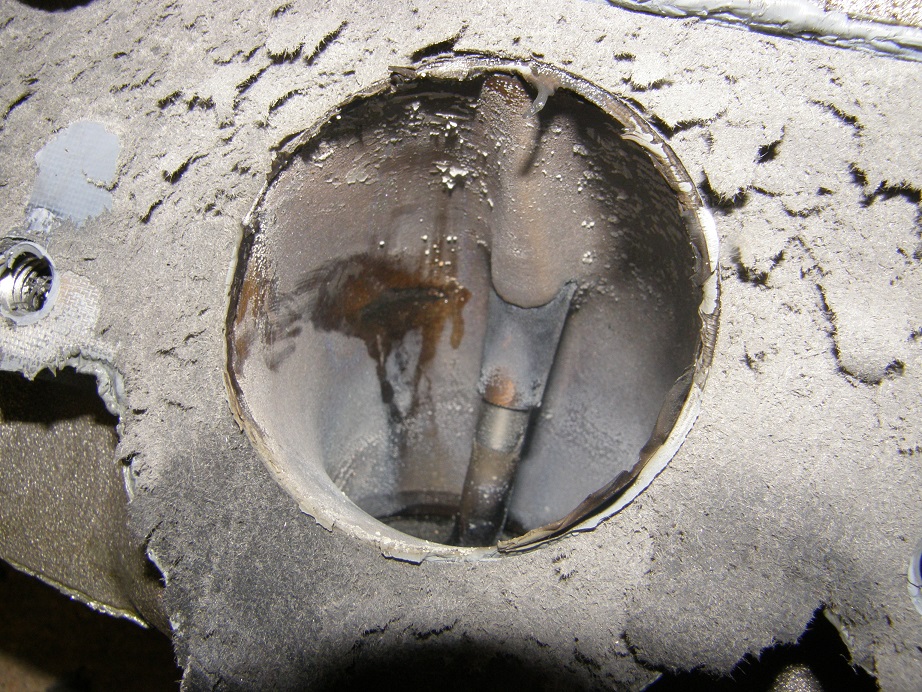
Fast forward to last weekend.  I had the engine mostly disconnected, and my friend and Drag Week co-pilot Steve (aka  57 Lima Bean and/or the Drunk Monkey) came over to help me get the engine out.  We decided to leave the trans in the car and after some screwing around finally pulled the engine clear.  Later that evening I started the tear down.  As soon as I pulled the intake manifold I realized that the leak was not in the head gaskets, it was the head.  The #2 intake port showed a clear coolant leak path:


These heads had leaked when I got them; the castings showed a lot of porosity in the ports so I’d had them checked, and sure enough they leaked.  But the leaks had been in the exhaust ports.  When I took them in for a max effort porting job, my porting guy broke through into the water jacket in the intake ports, so all the intake ports had to be welded, in addition to the exhaust ports where the leaks had originally been found.  Welding in the intake ports had been particularly troublesome, requiring several passes, so I assume that the welding in the #2 intake port was marginal and resulted in the coolant seepage I had discovered.

Now, with the addition of a cylinder head issue I had another decision to make.  My original plan for DW16 was to run the existing set of heads.  However I had been working on a new set of heads.  I had dropped these heads off for porting at my porting guy’s place in November, and told him I needed them back at the end of January.  These heads had never leaked, but I expected the same kind of issues with breaking through into the water jacket ports so I expected they would have to be welded also.  As usual my porting guy took longer than originally planned but he did get an additional 30 cfm out of the heads, up to 475@0.800” on the intakes.  Over the last couple of months I’ve been shuttling these heads from the porting guy to the welder and back, trying to get the welding done and sealed up so that eventually I could run the heads.  After finding the leak in the existing heads, I decided I may as well run the new heads.  The port configuration has changed though, so I will have to build a new intake manifold to work with these heads.  I figured I could squeeze that in sometime in the next month, and still have the engine back together, on the dyno, and then back in the car by early August.  Plenty of time (LOL!).

Back to the teardown.  After getting the engine torn down to the short block, I rotated the crank so that I had a clear view of the two dings in the #4 cylinder wall, and went in there with my dial bore gauge to measure how deep they were.  One was about 0.003” deep, and the other was about 0.005”.  Increasing the bore past 0.009” in diameter wasn’t possible because of piston ring size constraints, so I ended up settling on a 0.008” overbore on that cylinder.  That would take out the one ding and the scratch in the bore, and leave the other ding only about 0.001” deep and very narrow, probably less than 0.100” wide.  I figured this would be an improvement and I could live with that.  I had Blair order one piston for #4 at 0.008” oversize, for expedited one week delivery ($$$).  Figured I’d have the piston the week of July 5, and could get the block honed to size and get the short block back together the weekend of July 9-10. 

Last week I did my best to accelerate work on the new heads.  They needed guides and seats, so I got those ordered and they should be delivered this coming week.  My cylinder head guy has promised to get them finished up as soon as he gets the parts, and now that the heads have been welded and they passed the pressure check, I should have them by the weekend of July 16.  Things were shaping up for the engine to be back together and on the dyno by the end of the month, and back in the car by early August.

Unfortunately, that whole plan may have gone out the window this weekend.  Saturday morning I decided to tear down the short block.  I needed to do that anyway so that the #4 cylinder could be honed for the new piston, but because of the connecting rod failure at DW14, I am now fully paranoid about connecting rods.  So I decided to take the short block apart, pull the rods off  the pistons, and get them magnafluxed just to be sure they were all still good.  I pulled the first piston/rod assembly out of the block and started removing the rings.  These pistons have the pin going through the oil ring groove, and use a support rail at the bottom of the oil ring groove to support the oil rings, so those rings have to come out in order to remove the pin.  When I got to the oil rings, though, as I started to pull the top oil ring, I found that it was stuck in place part of the way around the piston.  Hmmmm…  I very carefully worked it loose, because I wanted to re-use these rings, since they were already seated to the bore. Then I removed the expander ring and the lower oil ring, and saw the problem.  The oil ring support rail had moved! 

There is a small dimple in the oil ring support rail that has to point down and line up with the pin hole.  The dimple is supposed to keep the oil ring support rail from rotating past the pin hole.  Obviously, this did not work, as the oil ring support rail had rotated over 90 degrees.  When it rotated, the dimple on the bottom side dug a groove into the bottom oil ring land of the piston!  See the photo below:


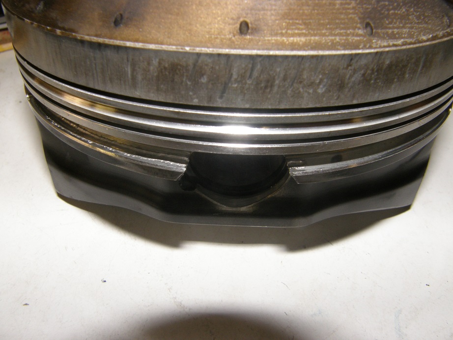
It looks like the oil ring rail rotated both ways, with the dimple digging a short groove in one side, and then a much longer groove in the other side.  Here’s a picture of the end of the longer groove:


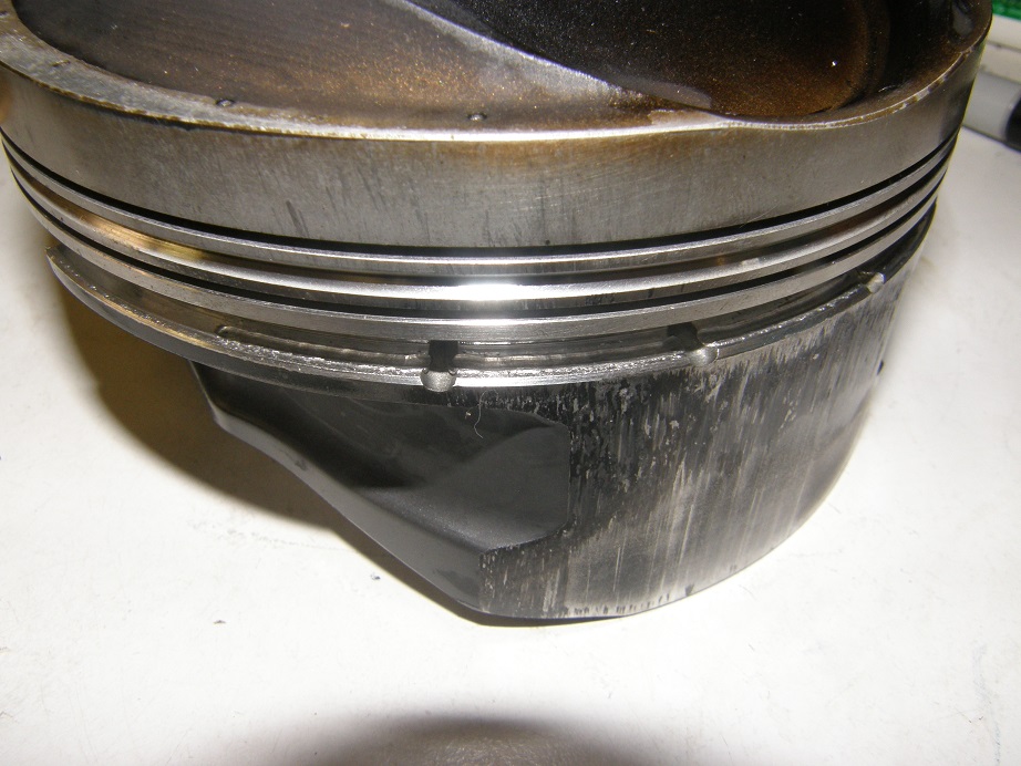
Not only that, but there was severe piston scuffing on that side of the piston!  See the photo below:


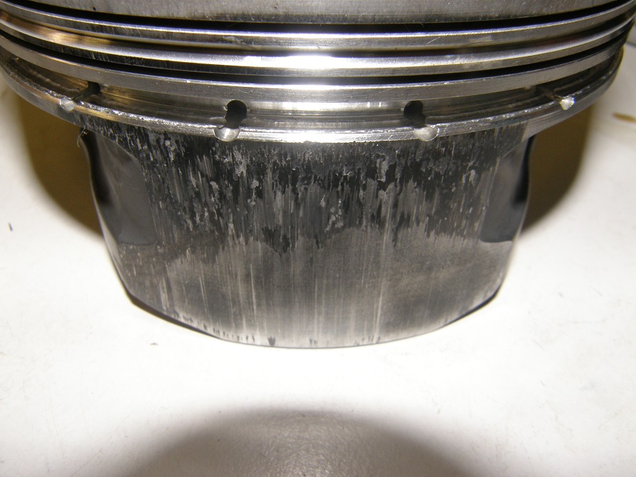
The oil rings were stuck because they were wedged between the raised oil ring rail and the ring land.  I have never seen a failure like this before.  I went ahead and continued to pull the piston rod assemblies, and remove the rods for magnafluxing.  I found that to some extent, all 8 pistons had shown the oil ring rail movement.  Three of the pistons showed minimal movement, around ½” or less, while the other five showed the groove from the dimple extending at least 90 degrees around the piston.  Three of these five showed the scuffing problem.  None of the pistons with minimal movement of the oil ring rail had any scuffing.

Anyone else seen this problem before?  Looking at the bottom oil ring land it is thin at the start of the pin hole, and I think this would make it easier for that dimple in the oil ring support rail to start digging in to the oil ring land.  The solution may be as simple as filing this sharp edge until it is thicker, which should make it more difficult for the dimple to start cutting into the ring land.  But the whole situation seems very strange.  I’ll bet I’ve assembled and disassembled a dozen engines with the oil ring support rails on the pistons, and I’ve never seen this problem before.
In any case, though, I’m thinking that I will need a new set of pistons for this engine, not just the one piston that I have already ordered.  And I don’t know about the lead time for a new set.  So, right now Drag Week 2016 is kind of up in the air for me; I may not make it with this car.  I may have to go back with the Mach 1 if I can’t get this one together in time.  I guess when  I find out about the lead time for a new set of pistons, I’ll be able to figure that out.  Of course, what would the lead-up to Drag Week be without some mechanical drama and a last minute thrash LOL!  Here’s a picture of the car as it sits right now:


In the meantime this weekend I finally got around to solving the steering rack issue.  With the oil pan off I was able to fit it over the K-member and see where I had space to put in some stops to fix the rack in place.  A couple of simple brackets, one side fixed and one side with a screw for an adjustment, solved that problem.

Tomorrow on the Fourth of July holiday I plan to get started on the finishing bodywork on the two bumpers, so that I’m ready to try the fiberglass chroming process within the next couple of weeks.  I’m going to try to have everything ready so that if I can get the pistons in a reasonable time period, I can still go with this car.  We will see what happens.  I will try to put up another update next weekend - Jay
« Last Edit: July 04, 2016, 08:28:50 AM by jayb »
Jay Brown
- 1969 Mach 1, Drag Week 2005 Winner NA/BB, 511" FE (10.60s @ 129); Drag Week 2007 Runner-Up PA/BB, 490" Supercharged FE (9.35 @ 151)
- 1964 Ford Galaxie, Drag Week 2009 Winner Modified NA (9.50s @ 143), 585" SOHC
- 1969 Shelby Clone, Drag Week 2015 Winner Modified NA (Average 8.98 @ 149), 585" SOHC


afret

  • Guest
Re: The Road to Drag Week 2016 - July 3, 2016
« Reply #1 on: July 03, 2016, 07:27:49 PM »
Wow, sorry to hear about all the problems.  Good thing though that you decided to check the engine out and not just run it at DW.  Hope it doesn't take too long for the pistons.  I'm sure if anyone can meet the deadline for DW it's you.  Good luck!!


AlanCasida

  • Hero Member
  • *****
  • Posts: 1099
    • View Profile
Re: The Road to Drag Week 2016 - July 3, 2016
« Reply #2 on: July 03, 2016, 11:57:14 PM »
Geez Jay, when it rains it pours huh. Sorry about all the issues you've had this year. Hang in there. 

Bolted to Floor

  • Hero Member
  • *****
  • Posts: 596
    • View Profile
Re: The Road to Drag Week 2016 - July 3, 2016
« Reply #3 on: July 04, 2016, 12:40:10 PM »
Sorry to hear about the family issues. Hope that your wife, dad, and dog are all on the mend.

I always look forward to the Road to Drag week chronicles. I had to endure a little bout of depression last year when you didn't include us.  :-\ Thanks for everything.  ;)
John D -- 67 Mustang 390 5 speed

jayb

  • Administrator
  • Hero Member
  • *****
  • Posts: 7406
    • View Profile
    • FE Power
Re: The Road to Drag Week 2016 - July 3, 2016
« Reply #4 on: July 04, 2016, 01:31:01 PM »
Sorry to hear about the family issues. Hope that your wife, dad, and dog are all on the mend.

Everybody is doing better, thanks. 
Jay Brown
- 1969 Mach 1, Drag Week 2005 Winner NA/BB, 511" FE (10.60s @ 129); Drag Week 2007 Runner-Up PA/BB, 490" Supercharged FE (9.35 @ 151)
- 1964 Ford Galaxie, Drag Week 2009 Winner Modified NA (9.50s @ 143), 585" SOHC
- 1969 Shelby Clone, Drag Week 2015 Winner Modified NA (Average 8.98 @ 149), 585" SOHC


turbohunter

  • Hero Member
  • *****
  • Posts: 2509
    • View Profile
Re: The Road to Drag Week 2016 - July 3, 2016
« Reply #5 on: July 04, 2016, 02:07:33 PM »
Wow, great catch.
Can just imagine had you just decided to run it.

I have to admit also that as much of a pain as it is for you, I enjoy the hell out of your DW chronicles.

Glad all is getting back to some form of normal for you at home.
Marc
'61 F100 292Y
'66 Mustang Injected 428
'66 Q code Country Squire wagon


cammerfe

  • Hero Member
  • *****
  • Posts: 1659
    • View Profile
Re: The Road to Drag Week 2016 - July 3, 2016
« Reply #6 on: July 06, 2016, 02:52:33 PM »
Some years ago we solved a ring-over-the-wrist-pin-hole scenario by installing teflon (impregnated with graphite) plugs into the ends of the wristpins. In effect, they filled-up the holes and made possible a support for the oil rings. The bottom support rail was then free to rotate and not do any damage to the piston.

It's been long enough ago that I can't tell you where the plugs came from. I have a vague notion they came from the piston company. I seem to remember that we were using Forged-True so it's probably no help.

KS

WConley

  • Hero Member
  • *****
  • Posts: 1160
  • No longer walking funny!
    • View Profile
Re: The Road to Drag Week 2016 - July 3, 2016
« Reply #7 on: July 07, 2016, 01:49:11 PM »
Wow Jay - I just caught this.  Sorry to hear about the family drama and I'm glad everybody is doing OK now.  Life has a way of getting you...  My mom got sick a few months ago and is going through chemo, but fortunately it looks like her medium-term prognosis is good.

On the piston front, is the wrist pin end-float hammering the spiro-locs? That would be something to look at, especially given your offset bore.  The unbalanced loads on the rod would want to make that pin dance back and forth.  Maybe look at the inside piston pin lands for evidence of wear/ impact damage.  Any heat damage evident on those skirts?

Best of luck getting the car back together.  At least your summers are consistent these past few years!

- Bill
« Last Edit: July 07, 2016, 02:20:23 PM by WConley »
A careful study of failure will yield the ingredients for success.

57 lima bean

  • Guest
Re: The Road to Drag Week 2016 - July 3, 2016
« Reply #8 on: July 09, 2016, 12:34:30 PM »
"I may have to go back with the Mach 1 if I can’t get this one together in time"

  Does this engine not too need attention?

machoneman

  • Hero Member
  • *****
  • Posts: 3853
    • View Profile
Re: The Road to Drag Week 2016 - July 3, 2016
« Reply #9 on: July 10, 2016, 09:23:31 AM »
Wow Jay sorry to hear of the family issues but good they seem to be resolved.

Bad engine news for sure. That skirt damage is rare to non-existent in any gas powered engine I've ever seen yet is common in nitro/alky engine. However, that occurs due to pinched ring lands on pistons run too lean or too much advance. I can see though how your moving oil rings could do this. 2X btw on the old Top Fuel style teflon pin end "buttons" for extra support.

http://www.bing.com/images/search?q=Teflon+Piston+Pin+Buttons&FORM=IRMHRS

On edit: that bad bearing is a head scratcher to me though as even Blair's explanation is shaky....at least to me. Maybe a tad more introspection on what's going on there. JMO! 
« Last Edit: July 10, 2016, 08:18:40 PM by machoneman »
Bob Maag

Barry_R

  • Hero Member
  • *****
  • Posts: 1915
    • View Profile
    • Survival Motorsports
Re: The Road to Drag Week 2016 - July 3, 2016
« Reply #10 on: July 10, 2016, 11:42:03 AM »
I have also been dealing with a few family issues - I very much sympathize with the time challenges they deliver.

On the engine I have a few thoughts.  The bearing looks like incipient fatigue failure to me.  Just getting beyond its design/material limits in that localized area.  Might be driven by reduced load contact area from crank or block deformation under load, or by bearing or crank dimensionals.  Just add new parts, keep an eye on filters - probably not a huge deal.

Piston looks like deformation.  I agree with the prior comment & wager the ring grooves are no longer to spec.  Top is probably loose, second tight, and oil too loose except where there was no support.  Opened things up enough that the spacer was free to roam.  Grooves are from the locating divot wandering around and getting popped down from cylinder pressure, rather than being forced to cut into the groove.

Any signs of top ring butting?

Hemi Joel

  • Sr. Member
  • ****
  • Posts: 497
    • View Profile
Re: The Road to Drag Week 2016 - July 3, 2016
« Reply #11 on: July 10, 2016, 02:33:03 PM »
Jay, that carnage is shocking! I don't think that poor motor would have made it thru another Drag Week!  Question/idea:  At DW 2015, you had issues with the fuel pump relay wire, and the fuel was shut off at mid track several times. Could that have caused a momentary lean condition that led to the damage?
WHat a coincidence that you have water leaking into an intake port, just like my 392 Hemi did on your dyno.  Maybe it's your dyno's fault.  :o :P ;D

Good luck with the repairs. 

Limabean, If I remember right, the high-riser motor in the Mach I is fine. It was the transe and rear end that broke, and I think they are both fixed.

Joe-JDC

  • Hero Member
  • *****
  • Posts: 1490
  • Truth stands on its own merit.
    • View Profile
Re: The Road to Drag Week 2016 - July 3, 2016
« Reply #12 on: July 10, 2016, 03:33:45 PM »
There are those 9 horsepower you couldn't find!  LOL.  Sorry about all the problems and issues with family, they take priority over cars.  You take care not to burn yourself out.  Take some time to relax.  Hopefully you can get everything to come together quickly and make up for the troubles that have plagued you so far.  That oversize bore might be just the ticket for those 9 additional horsepower.  Joe-JDC 
Joe-JDC '70GT-500

jayb

  • Administrator
  • Hero Member
  • *****
  • Posts: 7406
    • View Profile
    • FE Power
Re: The Road to Drag Week 2016 - July 3, 2016
« Reply #13 on: July 10, 2016, 05:44:03 PM »
I have also been dealing with a few family issues - I very much sympathize with the time challenges they deliver.

On the engine I have a few thoughts.  The bearing looks like incipient fatigue failure to me.  Just getting beyond its design/material limits in that localized area.  Might be driven by reduced load contact area from crank or block deformation under load, or by bearing or crank dimensionals.  Just add new parts, keep an eye on filters - probably not a huge deal.

Piston looks like deformation.  I agree with the prior comment & wager the ring grooves are no longer to spec.  Top is probably loose, second tight, and oil too loose except where there was no support.  Opened things up enough that the spacer was free to roam.  Grooves are from the locating divot wandering around and getting popped down from cylinder pressure, rather than being forced to cut into the groove.

Any signs of top ring butting?
Barry, thanks for the thoughts.  Blair thinks the piston issue was from detonation, but I don't know; there is no other sign of detonation.  I did check the ring grooves and they are right on for the top and second ring, and the oil ring groove is also right on where there was no damage from the divot in the support rail.  The pistons all measure perfect across the skirts also.  No sign of the ring butting either, although I'm not sure I've ever seen that.  I'm looking for a polished ring end to detect that condition, right?  The file marks are still visible on the ends, and they don't look polished, so I assume that's not a problem.  I just can't figure out this issue...
Jay Brown
- 1969 Mach 1, Drag Week 2005 Winner NA/BB, 511" FE (10.60s @ 129); Drag Week 2007 Runner-Up PA/BB, 490" Supercharged FE (9.35 @ 151)
- 1964 Ford Galaxie, Drag Week 2009 Winner Modified NA (9.50s @ 143), 585" SOHC
- 1969 Shelby Clone, Drag Week 2015 Winner Modified NA (Average 8.98 @ 149), 585" SOHC


jayb

  • Administrator
  • Hero Member
  • *****
  • Posts: 7406
    • View Profile
    • FE Power
Re: The Road to Drag Week 2016 - July 3, 2016
« Reply #14 on: July 10, 2016, 05:48:00 PM »
Jay, that carnage is shocking! I don't think that poor motor would have made it thru another Drag Week!  Question/idea:  At DW 2015, you had issues with the fuel pump relay wire, and the fuel was shut off at mid track several times. Could that have caused a momentary lean condition that led to the damage?
WHat a coincidence that you have water leaking into an intake port, just like my 392 Hemi did on your dyno.  Maybe it's your dyno's fault.  :o :P ;D


That's it, blame the dyno  ::)

I was using straight Q-16 at the track, so I don't think for the amount of time it ran out of fuel that this would have caused the problem.  I'm much more suspicious of the bad tank of gas I got when we went around Chicago on Tuesday night.  I ran probably 100 miles with occasional rattling due to the fuel; in fact I mentioned that in my blog.  If the problem is indeed detonation related, I'll bet that's when it happened...
Jay Brown
- 1969 Mach 1, Drag Week 2005 Winner NA/BB, 511" FE (10.60s @ 129); Drag Week 2007 Runner-Up PA/BB, 490" Supercharged FE (9.35 @ 151)
- 1964 Ford Galaxie, Drag Week 2009 Winner Modified NA (9.50s @ 143), 585" SOHC
- 1969 Shelby Clone, Drag Week 2015 Winner Modified NA (Average 8.98 @ 149), 585" SOHC


57 lima bean

  • Guest
Re: The Road to Drag Week 2016 - July 3, 2016
« Reply #15 on: July 10, 2016, 06:06:29 PM »
Limabean, "If I remember right, the high-riser motor in the Mach I is fine. It was the transe and rear end that broke, and I think they are both fixed"......They IS.The Mach 1 needs a look see.

Barry_R

  • Hero Member
  • *****
  • Posts: 1915
    • View Profile
    • Survival Motorsports
Re: The Road to Drag Week 2016 - July 3, 2016
« Reply #16 on: July 10, 2016, 10:24:57 PM »
Yeah - you'd see shiny spots on the gap.  I did a blown engine several years ago and it showed up pretty bad - needed to touch hone, open up gaps, and re-ring that one.  I don't see signs of detonation on the piston - usually it will nibble away at the sharp edges and corners, like the outside diameter and gas ports - those look clean.

Can you take pics of the rings from the sides?  Might be a clue there - maybe.

I was initially thinking that the ring issue contributed to the skirt, but maybe it's "chicken and egg" and the skirt was the initial failure.  Scuffed material might have dragged the ring around.?.?.   What can you provide regarding wall clearances, vacuum, distance from pin centerline to top of piston (Cammer engines require a lot of crevice volume above the top ring, which would intuitively make for a lot of potential rock in the piston.  How much clearance is between the wall and the above the top ring area?  A couple years ago I saw a Mahle design that intentionally used the upper area as added skirt/wall contact surface - something that nobody I was aware of ever did.  Maybe a case could be made for a longer skirt on the thrust side along with more clearance.

Thinking & typing out loud....

jayb

  • Administrator
  • Hero Member
  • *****
  • Posts: 7406
    • View Profile
    • FE Power
Re: The Road to Drag Week 2016 - July 3, 2016
« Reply #17 on: July 11, 2016, 08:08:18 AM »
I suppose its possible that the skirt was the initial failure, but the scuffing only shows up on three pistons, and all 8 of them show evidence of the support rail moving into the lower ring land; minimum was about 1/4" in, and max was 1/3 of the way around the piston. 

Last night I took the one piston I have left here (the rest are now at the machine shop), and re-assembled the oil ring support rail and oil rings after I had filed down the burrs in the lower ring land and also cleaned up the area by the pin so that the dimple in the support rail is pushing against a vertical wall instead of a thin, tapered spot.  I pushed on the dimple in the support rail with a screwdriver, trying to get it to move into the ring land, and it wouldn't budge.  This leaves me hopeful that this little fix will solve the problem, but I think I'm going to have to re-assemble the engine, run it, and then tear it down again before I know for sure...
Jay Brown
- 1969 Mach 1, Drag Week 2005 Winner NA/BB, 511" FE (10.60s @ 129); Drag Week 2007 Runner-Up PA/BB, 490" Supercharged FE (9.35 @ 151)
- 1964 Ford Galaxie, Drag Week 2009 Winner Modified NA (9.50s @ 143), 585" SOHC
- 1969 Shelby Clone, Drag Week 2015 Winner Modified NA (Average 8.98 @ 149), 585" SOHC


TomP

  • Guest
Re: The Road to Drag Week 2016 - July 3, 2016
« Reply #18 on: July 13, 2016, 03:53:28 PM »
An old set of JE pistons I've got use aluminum plugs to retain the pin and have the ring grooves cut in them. They are a 1.13" compression distance so the rings have to overlap the pins. Seems like a way to eliminate snap rings or Spirolox as well.

Heo

  • Hero Member
  • *****
  • Posts: 3287
    • View Profile
Re: The Road to Drag Week 2016 - July 3, 2016
« Reply #19 on: July 13, 2016, 06:08:21 PM »
Aluminium buttons to retain the piston pin is used on aero
engines


The defenition of a Gentleman, is a man that can play the accordion.But dont do it

427Fastback

  • Hero Member
  • *****
  • Posts: 603
    • View Profile
Re: The Road to Drag Week 2016 - July 3, 2016
« Reply #20 on: July 13, 2016, 07:54:59 PM »
At one of the shops I worked at we had two flat bottom drag boats.One was a 500+ aluminum KB (blown alky)It used Teflon buttons on the wrist pins...
1968 Mustang Fastback...427 MR 5spd (owned since 1977)
1967 Mustang coupe...Trans Am replica
1936 Diamond T 212BD
1990 Grizzly pick-up

Qikbbstang

  • Hero Member
  • *****
  • Posts: 892
    • View Profile
Re: The Road to Drag Week 2016 - July 3, 2016
« Reply #21 on: August 26, 2016, 09:13:37 AM »
Just a general question with all the welding of the ports required on the heads I was under the impression that the "spec" on aluminum and heads was derived via a careful heating & cooling process. Supposedly welding on heads and alum can knock that hardness out making them 'soft' ... when alum heads are substantially welded do mortals get them re-heat treated?..............

jayb

  • Administrator
  • Hero Member
  • *****
  • Posts: 7406
    • View Profile
    • FE Power
Re: The Road to Drag Week 2016 - July 3, 2016
« Reply #22 on: August 26, 2016, 11:05:02 AM »
I've never had to do that, but then the welding is in the ports, not around threaded areas where hardness is more critical.
Jay Brown
- 1969 Mach 1, Drag Week 2005 Winner NA/BB, 511" FE (10.60s @ 129); Drag Week 2007 Runner-Up PA/BB, 490" Supercharged FE (9.35 @ 151)
- 1964 Ford Galaxie, Drag Week 2009 Winner Modified NA (9.50s @ 143), 585" SOHC
- 1969 Shelby Clone, Drag Week 2015 Winner Modified NA (Average 8.98 @ 149), 585" SOHC


Cyclone Joe

  • Full Member
  • ***
  • Posts: 137
  • Joe
    • View Profile
Re: The Road to Drag Week 2016 - July 3, 2016
« Reply #23 on: August 26, 2016, 01:51:36 PM »
BB,
The aluminum heads are not heat treated but left in the 'as fabricated', meaning there isn't any post cast heat treatment for strengthening purposes.  Welding isnt going to cost you any strength, as you're in the lowest strength/stress condition in the as-fabricated state.  Now, by operating the engine, you end up heat treating part of the head over time to a T5 or T51 temper, as you only need 300-400F to start that process.  It can start with an even lower temp, say 225-250F, which more of the head could see.

Here's a good article for reference purposes http://www.afsinc.org/files/images/aluminum.pdf

Joe

jayb

  • Administrator
  • Hero Member
  • *****
  • Posts: 7406
    • View Profile
    • FE Power
Re: The Road to Drag Week 2016 - July 3, 2016
« Reply #24 on: August 26, 2016, 04:38:31 PM »
I don't think that's correct, Joe.  My intake adapters are solution heat treated to T6, and I'm pretty sure that cylinder heads have to go through the same treatment.  One reason is machining; if you don't heat treat the aluminum casting, you end up tearing the metal much more easily when machining the parts, and I think it would be very difficult to get that smooth finish you see on the decks of aluminum cylinder heads. 

I know for a fact that some SOHC heads are heat treated after casting, and I assume all other aluminum aftermarket heads are done the same way - Jay
Jay Brown
- 1969 Mach 1, Drag Week 2005 Winner NA/BB, 511" FE (10.60s @ 129); Drag Week 2007 Runner-Up PA/BB, 490" Supercharged FE (9.35 @ 151)
- 1964 Ford Galaxie, Drag Week 2009 Winner Modified NA (9.50s @ 143), 585" SOHC
- 1969 Shelby Clone, Drag Week 2015 Winner Modified NA (Average 8.98 @ 149), 585" SOHC


Cyclone Joe

  • Full Member
  • ***
  • Posts: 137
  • Joe
    • View Profile
Re: The Road to Drag Week 2016 - July 3, 2016
« Reply #25 on: August 26, 2016, 04:54:00 PM »
Jay,
Did the casting house share why they go up to a T6 temper rather than leaving it "F"?  Was it to stabilize the casting during machining?  Based on the thermal cycles the part will see on the operating engine, its going to re-temper it down to a T5 anyways, so I'm more curious than anything why they go up to T6.  If it were bar stock I'd get it; clearly I need to study more on cast aluminum  ;)

I wonder how much machine-ability difference there would be, we're talking 6-7% elongation in "F" to 3-4% in the T6 condition.  I could see the argument if the "F" condition was 20% as it would be 'mushy' rather than want to form a chip.  Again, more learning on my behalf needed.  :)

Learned something new today either way, thanks Jay!

Joe 

Joe-JDC

  • Hero Member
  • *****
  • Posts: 1490
  • Truth stands on its own merit.
    • View Profile
Re: The Road to Drag Week 2016 - July 3, 2016
« Reply #26 on: August 26, 2016, 08:50:34 PM »
TFS, Edelbrock, Ford all had warnings on cutting too much off the fire deck when their aluminum heads were first brought to the public for use.  Edelbrock used to say that anything over .050" would require sending them back for heat treatment for them to stay flat and not blow head gaskets, or lose their valve jobs.  Many of the small block Ford heads would only get a few races before the valves would no longer seal properly.  The reason was cutting too much off the entire surface weakened the head.   Heat treating is not usually needed where welding is done.  I just repaired a combustion chamber this week for my old shop where they welded the combustion chamber almost entirely up, and cut the chamber to install new valve seats and welded the guide hole before cutting and installing a new guide.  When I finished, it looked like the original CNC combustion chambers of the other three cylinders.  Anyway, if you have an aluminum head and it has been welded on, or cut the deck excessively, you may find the valve job will not seal for long.  If that happens, then it could need a heat treatment issue.  Joe-JDC
Joe-JDC '70GT-500

jayb

  • Administrator
  • Hero Member
  • *****
  • Posts: 7406
    • View Profile
    • FE Power
Re: The Road to Drag Week 2016 - July 3, 2016
« Reply #27 on: August 26, 2016, 09:02:22 PM »
Jay,
Did the casting house share why they go up to a T6 temper rather than leaving it "F"?  Was it to stabilize the casting during machining?  Based on the thermal cycles the part will see on the operating engine, its going to re-temper it down to a T5 anyways, so I'm more curious than anything why they go up to T6.  If it were bar stock I'd get it; clearly I need to study more on cast aluminum  ;)

With all three of the casting companies I've worked with, T6 seems to be pretty standard for any casting over about 10 pounds.  The first thing they say is T6 improves machinability, and they also recommend some ageing of the casting, again for machinability.  They also mention thread integrity; if you are going to put threads in the casting, T6 will make them hold more torque.  In addition, with a cylinder head where you are torquing them with bolts or studs to 100 foot pounds or so, a soft casting will compress and you won't get a good torque on the bolts without warping the heads somewhat. 
Jay Brown
- 1969 Mach 1, Drag Week 2005 Winner NA/BB, 511" FE (10.60s @ 129); Drag Week 2007 Runner-Up PA/BB, 490" Supercharged FE (9.35 @ 151)
- 1964 Ford Galaxie, Drag Week 2009 Winner Modified NA (9.50s @ 143), 585" SOHC
- 1969 Shelby Clone, Drag Week 2015 Winner Modified NA (Average 8.98 @ 149), 585" SOHC


Barry_R

  • Hero Member
  • *****
  • Posts: 1915
    • View Profile
    • Survival Motorsports
Re: The Road to Drag Week 2016 - July 3, 2016
« Reply #28 on: August 26, 2016, 10:17:58 PM »
I'm probably gonna goof this up since I am going by memory.  I recall a conversation with our lead engineer at the Malden, MO cast piston plant regarding heat treatment decisions on cast (hypereutectic) pistons.  That facility ran tens of thousands of pistons per day at one point, so they knew something about that stuff. 

He stated that on their castings (obviously much less than 10 pounds each) a T6 treatment would initially test better but would degrade over time and use.  He indicated that the T5 process would initially not test as well but would actually get better over usage and could actually exceed the T6 after accumulated run time.  I'll let those more knowledgable about the processes tell us if he was correct or just trying to get me to be quiet and go away....