I'm in the middle of making a few changes to my race car, and thought that this one might interest a few people. Last year the car was running way to much RPM, about 7700 through the traps during Drag Week, where power peak on the engine is around 6600-6800. I wanted to bring the RPM down some, so the first step was to change out the 4.29 gears for some 4.11s. In addition, the street tires I'm running are only 28" in diameter, and with the radiused wheelwells they look just a little small when they are on the car. So, I'm upgrading to a set of 30" tall tires.
These two changes taken together make it practical for me to drive the car on the street without the Gear Vendors overdrive. So, along with these changes I decided to remove the GVOD to save some weight, plus add an aluminum driveshaft to save a little more. The transmission is an ATI Superglide, but when I bolted the normal tailshaft housing onto the trans in place of the GVOD unit, one problem immediately became apparent: The ATI transmission tailshaft housing has no provision for a speedometer.
With as much street time as this car sees I didn't want to be running around without a speedometer, so I spent a little time investigating my options. I have a complete set of Autometer gauges in the car, including the speedometer, and when I checked Autometer's web site I found that they had an electronic speedometer available in the same style as my other gauges. After downloading the directions for the electronic speedo, I figured out that I could use the same kind of magnetic sensor as a pickup for the speedometer as I'm already using for cam and crank sensors on the engine. So this looked like a pretty good fit.
The byproduct advantage of the whole issue was that I would get a driveshaft speed sensor installed in the car. This could work with the speedometer, and the output could also be datalogged by my EFI system. A driveshaft speed sensor is really a nice sensor to have, because it lets you determine if the car is spinning the tires at the track, and also gives good information to help you dial in your clutch or torque converter. I've been threatening to install one for quite a while now, but there was going to be a lot of fabrication required, so I hadn't gotten it done. This weekend I decided to do it.
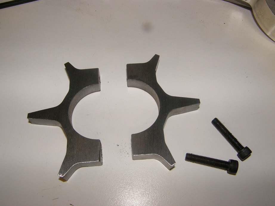
My business background is in magnetic sensors, and I know that the gear or "target" that the sensor has to pick up is critically important for good performance. The sensors that I'm using, which are Cherry GS1001 Hall effect sensors, give a suggested gear tooth profile in the data sheet, so I used that as a starting point and designed a six tooth gear that would clamp in place around the driveshaft yoke. I wrote a CNC program to machine the target in two parts, and then after cutting them out of cold rolled steel I drilled and tapped them so they would bolt together around the yoke. Here's a picture of the target:
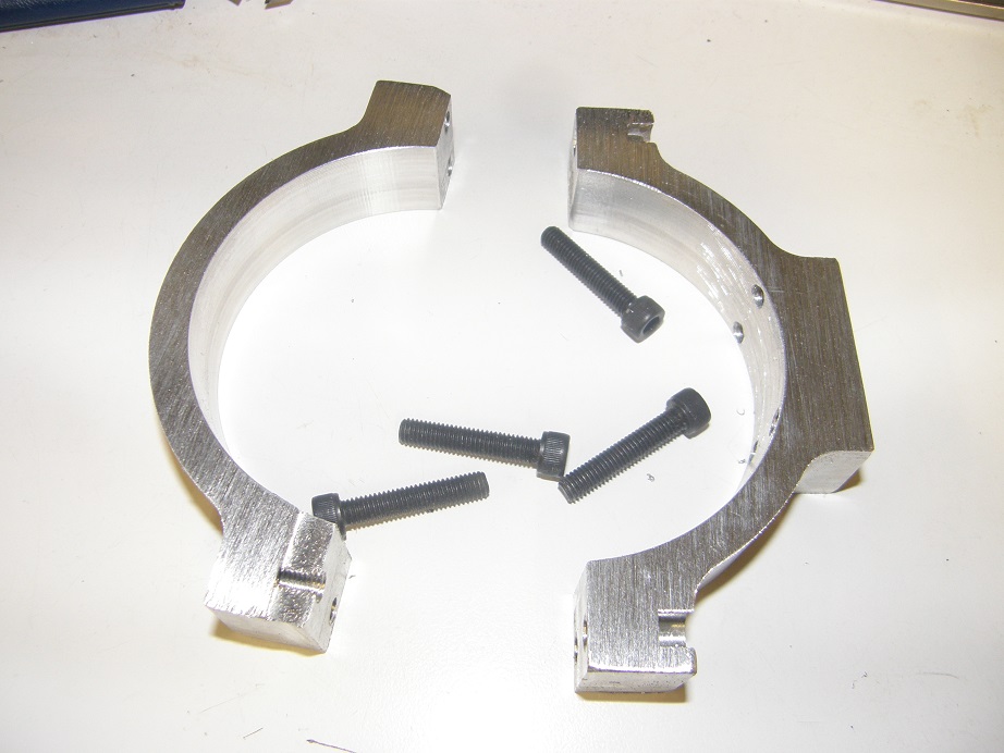
Next I had to design and build a bracket that would hold the sensor. Attaching it to the chassis didn't make a lot of sense to me, because the transmission mount is rubber, and the air gap between the sensor and the teeth of the target is pretty small, around 0.060". The logical place to mount the sensor was with a bracket attached to the tailshaft housing of the transmission, and fortunately for me this is a machined section on the ATI Superglide. I made up a drawing of what I wanted then machined the first part of the bracket out of aluminum. As often happens with my first time machining programs, a couple of minor machining errors crept in, but the part was still usable; picture below:
Note the raised portion on one of the bracket halves; I needed to machine another small piece to bolt to that, and hold the sensor. The sensor and the cable I'm using are shown in the photo below:
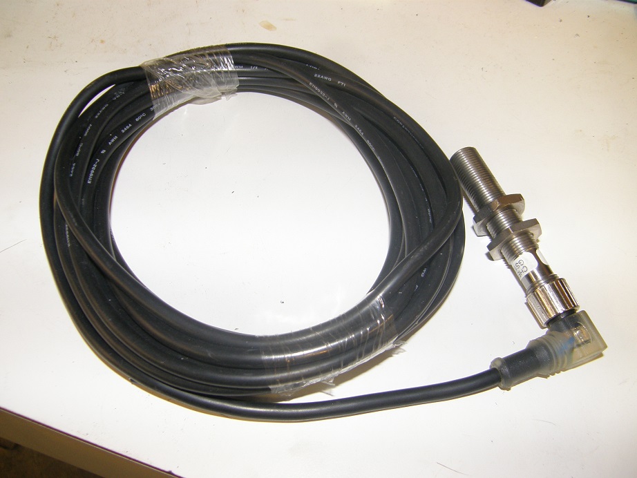
I like this sensor because the cable screws onto it; in case of a sensor failure, it can be disconnected from the cable and easily replaced. Also, the head of the cable has two LEDs built into it. One is a green LED that indicates the sensor is powered. The other is a yellow LED that lights up when there is no tooth present in front of the sensor, and goes out when the tooth is present. This makes it really easy to diagnose any sensor problems (or problems with the cable, for that matter).
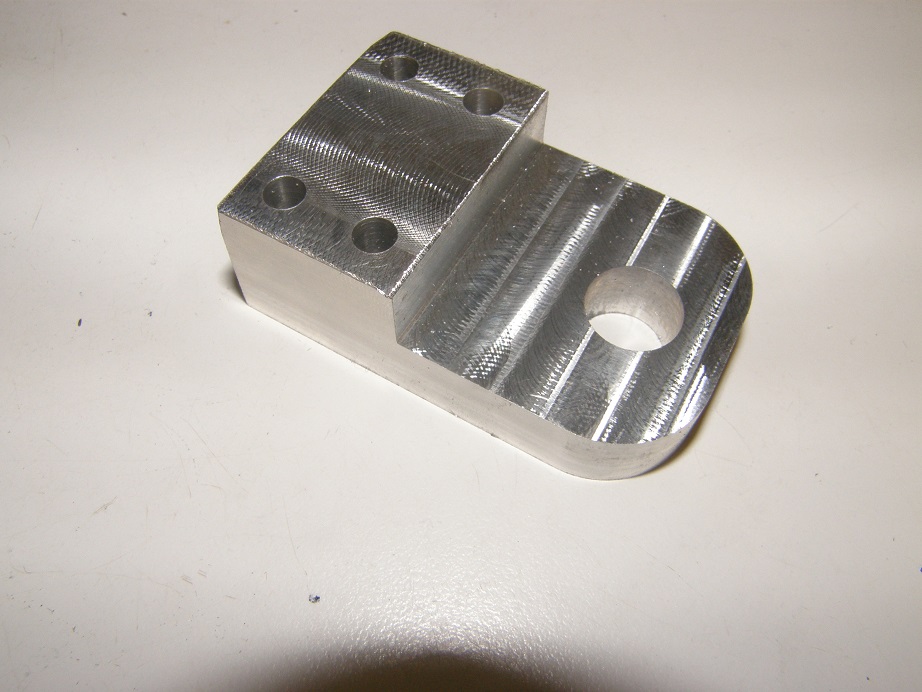
The body of the sensor is 12mm in diameter (about 0.470"), so I designed a bracket that would bolt onto the first one I made, and had a hole in it for mounting the sensor. Here's a pic:
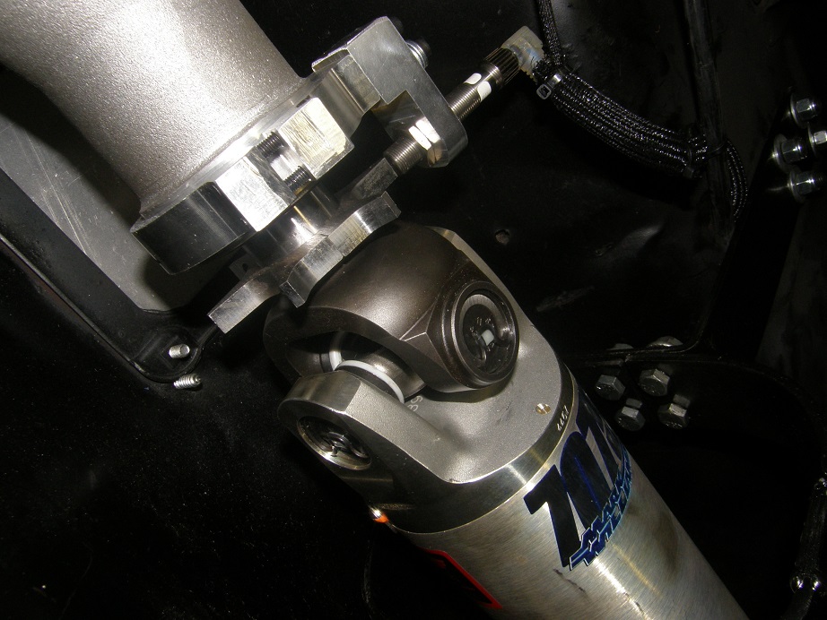
Finally I assembled the whole thing on the car, while adjusting the sensor position for the desired 0.060" airgap. The mounting appears very solid. I have not yet wired it up, but I don't expect any issues with making it work. Here's a picture of the whole thing assembled on the car:
This whole project took about 14 hours over the weekend, and is probably overkill, but I'm confident that it will survive in the vehicle. I'm anxious to try this setup out in the next month or so, when I start driving the car again. I will report back with any issues I find - Jay


