Author Topic: 519" SOHC Build  (Read 92466 times)

0 Members and 1 Guest are viewing this topic.

jayb

  • Administrator
  • Hero Member
  • *****
  • Posts: 7564
    • View Profile
    • FE Power
Re: 519" SOHC Build
« Reply #30 on: March 25, 2012, 11:38:24 AM »
Thanks Adam, that's pretty cool.  Here's a link if anyone else wants to look at them:

http://www.ebay.com/itm/427-SOHC-Stub-Cam-Sprocket-/280850666200?hash=item41640112d8&item=280850666200&vxp=mtr

I wish they had the .250" tooth on the secondary sprocket so that I could use Munro's chain with them; it would save me a lot of work pinning the two gears together.  But for anyone who is running the original .222" chain, that is a great solution to the problem.
Jay Brown
- 1969 Mach 1, Drag Week 2005 Winner NA/BB, 511" FE (10.60s @ 129); Drag Week 2007 Runner-Up PA/BB, 490" Supercharged FE (9.35 @ 151)
- 1964 Ford Galaxie, Drag Week 2009 Winner Modified NA (9.50s @ 143), 585" SOHC
- 1969 Shelby Clone, Drag Week 2015 Winner Modified NA (Average 8.98 @ 149), 585" SOHC


jayb

  • Administrator
  • Hero Member
  • *****
  • Posts: 7564
    • View Profile
    • FE Power
Re: 519" SOHC Build
« Reply #31 on: March 31, 2012, 11:54:10 PM »
More progress today on getting my 519" SOHC together.  This morning I got the heads cleaned up and then spent the afternoon checking the valvesprings, setting the spring height, and then installing the valves, springs, locks, and valve seals.  Here's a photo of one of the bare heads, and then a couple of photos of it after it has been completely assembled:


Once both the heads were finished up, I installed the studs in the block and then installed the heads temporarily.  I want to check piston to valve clearance in each cylinder, so I put clay on 7 of the 8 pistons before putting the heads on the block.  Here's a photo of the pistons with the clay on them, and then another photo of the engine assembled with the heads in place:


Next I had to put together the chain drive so I could roll the engine over and get impressions in all the pieces of clay.  This engine originally had the factory style .222" chain, which is a non-roller chain setup, and I had earlier decided to transition to Paul Munro's chain drive setup.  This meant that I had to change out the gears on the tensioner arm and the fuel pump gear stand.  This was pretty straightforward on the fuel pump gear stand, but when I got to the tensioner arm, Munro's gear wouldn't fit.  The tensioner arm I had on this engine was an aftermarket unit I got from Doug at Precision Oil Pumps, and it just wasn't wide enough to take the Munro gear.  Fortunately I have a spare stock tensioner arm, and a quick check showed that Munro's gear fit fine on the stock piece.  So, I pressed out the pin, removed the old gear and bearing, and installed Munro's gear with a new bearing. 

From there I took some time to clean up the backing plate that goes behind the timing cover; this has to be in place before the tensioner arm and fuel pump gear are installed, otherwise the gears won't line up correctly with the secondary drive gear on the stub cam.  Once the backing plate was installed I put it in place on the engine and then installed the two gears.  Next I found the cams I want to use on this engine, which are actually the same cams that I ran on my 585" motor last year, and after lubing the bearings installed them in the heads, tightening the first cam cap to hold them in position. 

Now it was time to put the chain on, and the Ford chains had three colored links, red, white, and blue, that lined up with the dots on the two cam gears and the dot on the secondary chain drive gear.  Munro's chain didn't have the markings on it, and few of the aftermarket chains do, so I took some paint markers (black, white, and yellow were on hand) and marked the chains in the correct spots.  In case anyone is interested in how far apart these marks are on the chain, you can randomly mark the first link to go to the left cam sprocket, then move 58 links to the left and mark that link to go on the secondary drive sprocket on the dot, and then move 64 more links to the left on the chain and mark that link to go on the right cam sprocket on the dot.  Here's a photo of the chain loosely installed on the engine:


Before you tighten the chain you have to install the front cover.  The reason is that if you don't, you will deflect the nose of the stub cam with the chain tension, potentially leading to an inaccurate timing reading or damaging the stub cam (especially if it is a cast iron stub cam, rather than a steel one).  The nose of the stub cam is fixed by a bearing in the front cover.  Mike was asking about this earlier; here's a photo of the bearing just placed on the nose of the stub cam.  You can see the snap ring groove in the stub cam just past the bearing location.  The bearing is pushed back against the step on the stub cam, so once the bearing is pressed into place in the front cover, and the stub cam pokes through the bearing, the snap ring locates the stub cam front to rear.  After the photo of the bearing is another photo showing the bearing being pushed into the Pond front cover:


Once the bearing was in place I installed the front cover on the engine with a few bolts, and then tightened up the chain before I called it a night.  Tomorrow I will find top dead center, time the cams, and then install all the rockers so I can roll the engine over a few times, and also check piston to valve clearance.  Then I'll pull it back apart and look at everything; hopefully I'll have plenty of clearance and I can assemble the engine for good after that.  I'll try to post a few more photos and details about this whole procedure tomorrow.

« Last Edit: April 28, 2012, 03:46:26 PM by jayb »
Jay Brown
- 1969 Mach 1, Drag Week 2005 Winner NA/BB, 511" FE (10.60s @ 129); Drag Week 2007 Runner-Up PA/BB, 490" Supercharged FE (9.35 @ 151)
- 1964 Ford Galaxie, Drag Week 2009 Winner Modified NA (9.50s @ 143), 585" SOHC
- 1969 Shelby Clone, Drag Week 2015 Winner Modified NA (Average 8.98 @ 149), 585" SOHC


Hemi Joel

  • Sr. Member
  • ****
  • Posts: 499
    • View Profile
Re: 519" SOHC Build
« Reply #32 on: April 01, 2012, 12:17:25 AM »
Youv'e been busy, as usual. Lookin' good!

Kerry j

  • Full Member
  • ***
  • Posts: 106
    • View Profile
Re: 519" SOHC Build
« Reply #33 on: April 01, 2012, 07:51:42 AM »
Looks like great progress to me Jay; but then I'm a Cammer wanna be and don't know enough about them to understand the significance of what you're doing. Are there books of manuals available where one can read up on or study these SOHC beasties?

jayb

  • Administrator
  • Hero Member
  • *****
  • Posts: 7564
    • View Profile
    • FE Power
Re: 519" SOHC Build
« Reply #34 on: April 01, 2012, 08:54:30 AM »
The only book available is the original factory service manual, which is being reprinted and sells for around $45 these days if I recall correctly.  However, now that you mention it, my next book project is an SOHC book.  It will probably be a couple years before that one is ready, though.
Jay Brown
- 1969 Mach 1, Drag Week 2005 Winner NA/BB, 511" FE (10.60s @ 129); Drag Week 2007 Runner-Up PA/BB, 490" Supercharged FE (9.35 @ 151)
- 1964 Ford Galaxie, Drag Week 2009 Winner Modified NA (9.50s @ 143), 585" SOHC
- 1969 Shelby Clone, Drag Week 2015 Winner Modified NA (Average 8.98 @ 149), 585" SOHC


Kerry j

  • Full Member
  • ***
  • Posts: 106
    • View Profile
Re: 519" SOHC Build
« Reply #35 on: April 01, 2012, 09:27:01 AM »
Do you know where I could get one of those manuals? I've looked on eBay and Amazon with no success.

machoneman

  • Hero Member
  • *****
  • Posts: 3859
    • View Profile
Re: 519" SOHC Build
« Reply #36 on: April 01, 2012, 09:45:33 AM »
Try Cushman. The internal website link to the SOHC manual is broken but an e-mail could verify if they still sell it or if they can supply you a source. Btw, if they don't e-mail back I'd spent a few bucks to call them.

 http://www.cushmancompetition.com/ford427.htm
Bob Maag

jayb

  • Administrator
  • Hero Member
  • *****
  • Posts: 7564
    • View Profile
    • FE Power
Re: 519" SOHC Build
« Reply #37 on: April 01, 2012, 09:49:13 AM »
I've seen them on ebay in the past; Cushman Competition may be a source as Bob suggests.  That book was $45 even 25 years ago, when I bought mine.  I remember how painful it was to shell out $45 for a car book in 1985.  To be honest though, that book is not the greatest source of information on the SOHC engines; there's a lot about the engine that they don't talk about.  I've learned the hard way about a lot of that stuff, which is why I want to write a book on them eventually.
Jay Brown
- 1969 Mach 1, Drag Week 2005 Winner NA/BB, 511" FE (10.60s @ 129); Drag Week 2007 Runner-Up PA/BB, 490" Supercharged FE (9.35 @ 151)
- 1964 Ford Galaxie, Drag Week 2009 Winner Modified NA (9.50s @ 143), 585" SOHC
- 1969 Shelby Clone, Drag Week 2015 Winner Modified NA (Average 8.98 @ 149), 585" SOHC


Kerry j

  • Full Member
  • ***
  • Posts: 106
    • View Profile
Re: 519" SOHC Build
« Reply #38 on: April 01, 2012, 10:09:42 AM »
Thanks guys, I'll do some digging and see what I can come up with.

cammerfe

  • Hero Member
  • *****
  • Posts: 1676
    • View Profile
Re: 519" SOHC Build
« Reply #39 on: April 01, 2012, 01:06:21 PM »
Jay, you got off easy! I went to Columbus with a pocket full of money about 15 years ago and I think I paid $75 for my copy. (And I'm told mine may be a re-print also!)

KS

WConley

  • Hero Member
  • *****
  • Posts: 1221
  • No longer walking funny!
    • View Profile
Re: 519" SOHC Build
« Reply #40 on: April 01, 2012, 02:53:35 PM »
I got mine in 1993, from one of the original Ford engineers on the SOHC project :-)  There were still a few floating around the building then.

My only regret is that another old timer had his Cougar GT-E for sale for $7K in reasonable driver condition.  Didn't have the room!
A careful study of failure will yield the ingredients for success.

fetorino

  • Full Member
  • ***
  • Posts: 150
  • Tunnelport Cobra
    • View Profile
Re: 519" SOHC Build
« Reply #41 on: April 01, 2012, 05:30:59 PM »
You are a brave man Jay messing with those cammers.  I can't wait to see the updated pics and hear how the valve clearances are working out. Those motors are awesome but considering the additional nuances they bring to the planning an build I am glad I only have a simple TunnelPort.

jayb

  • Administrator
  • Hero Member
  • *****
  • Posts: 7564
    • View Profile
    • FE Power
Re: 519" SOHC Build
« Reply #42 on: April 02, 2012, 12:41:30 AM »
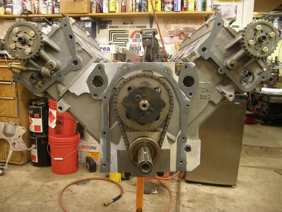
I was going to be out of town today, but the family plans changed at the last minute, so I had the opportunity to get more work done on this engine.  As it turned out what I had planned to do this morning before we were going to leave took me all day anyway LOL!  Its easy to forget that these engines don't just slam together like a normal FE; it takes a lot of screwing around to get one together and check everything. 

With the chain and front cover installed, I continued on mocking up the engine by installing the valve train.  First thing I did was loosen all the rocker arm adjusters and back them way off; I like to do this on these engines because you have to turn the engine over several times when you are going through the cam timing procedure, and if the timing is off by a significant amount you could run into piston to valve clearance problems if you were opening the valves all the way.  After backing off the adjusters I installed the rocker shafts and rocker arms into the heads, and then put the caps on the heads to hold everything in place.  Here's a photo of the engine at this point:


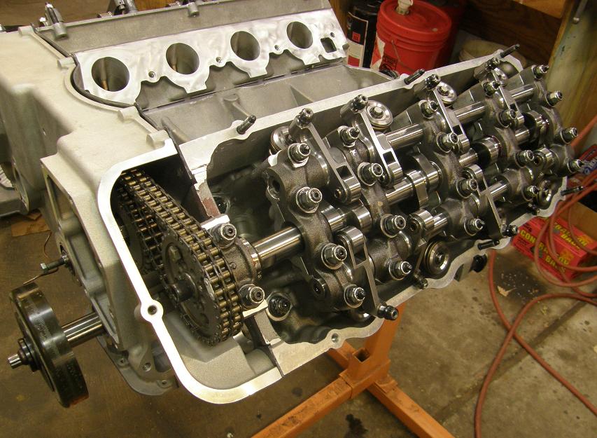
Notice in this photo that the rocker arms for cylinders 6, 7, and 8 are not over the valves; they are slid to one side on the rocker shaft so that they aren't in contact with the cam lobe, and therefore can't open the valves.  This is how you install the rocker shaft assemblies on these engines.  For the rocker arm and shaft assemblies on the left head, you have to rotate the engine until the rocker arms are on the heels of the cam lobe on cylinder 5, and then install the shafts with the remaining rockers slid out of the way so they aren't contacting the valves.  As you can see in the photo the rocker arms on cylinder 5 can't slide; they are captured by the cam towers on either side.  Rotating the cam so that these rockers are on the heel of their respective lobes, and sliding the other rockers away from the lobes on the shafts, allows you to install the shaft without tightening them down against the force of the valve springs.  So, there's no tension on the rocker shafts when they are installed using this method, as compared to a standard FE, where you have to install the rocker shafts and tighten them down against the valve spring pressure.

The same situation holds true with the right bank, where the rockers on cylinder 4 are captured between two cam towers but the other three rocker pairs are free to slide on the shaft.  After getting the shafts and rockers installed and the caps tightened down, you just turn the engine over a little at a time until one at a time the heel of each cam lobe comes up to the correct position and the associated rocker arm can be slid over into position on the valve; then the rocker arm spacer clip for that rocker is snapped in place over the shaft to hold the rocker in position.  Usually I end up taking two or three complete revolutions of the engine to get all the rocker arms into position.

Next I timed the cams.  I wanted to be at 110 degrees ATDC with both cams, but the caveat with these numbers is that based on the testing I did in 2007, the right cam retards about 2 degrees  between 3000 and 7000 RPM, and the left cam actually advances 2 degrees over the same range.  So, I wanted to target for 108 on the right cam and 112 on the left cam.  I wasn't real firm on these numbers, though, because the original tests I did in 2007 were with a standard .222" pin timing chain.  Munro's chain is a lot beefier, and has the .250" pins that you normally see on a doube roller timing chain set, so it is quite likely that the chain stretch would be reduced with this setup.  With that in mind I started the process by finding top dead center for cylinder #1; I use a dummy spark plug with a metal rod welded into it that protrudes into the combustion chamber and acts as a piston stop.  After going both ways and looking at the markings on the fully degreed ATI balancer, I made an adjustment to my wire pointer to set TDC.  Next I stuck a dial indicator on the #1 intake valve spring retainer and found the intake valve centerline using the Comp Cams method; it was at 116 degrees.  Changing the cam timing on these engines is pretty easy, and involves pulling a pin out of the gear that bolts to the end of the cam, rotating the cam with respect to the gear, and then replacing the pin in a different hole.  Moving the pin one hole moves the cam timing 1.5 cam degrees, or 3 crank degrees.  It looked like I would need to move the pin three positions to advance the cam to 107, which would make it close to the 108 that I wanted.  But when I did this it turned out when I rechecked the timing that the cam was exactly at 108 degrees; sometimes those holes aren't quite perfect, and in this case that worked to my advantage.

With the right cam timed I wanted to check piston to valve clearance.  On cylinder 1 I had not put in any clay, but instead had put checker springs on the valves so that I could read piston to valve clearance off a dial indicator.  Worst case piston to valve clearance is around TDC on the overlap portion of the stroke, and is usually around 10 degrees ATDC with the intake valves, and around 10 degrees BTDC on the exhausts.  I started with the intake valve at 20 degrees BTDC, and continued in 5 degree increments checking the clearance with a dial indicator.  I had adjusted the lash on the rocker arms to zero previously, so this was a worst case measurement; valve lash would add to the piston to valve clearance.  I found the minimum clearance at 10 degrees ATDC; it measured 0.078".  At 5* ATDC it was 0.087", and at 15* ATDC it was 0.092".  I try to maintain a minimum of 0.080", so with any valve lash at all I would meet this requirement, so it seemed like I was good to go here.

Moving to the exhaust valve, I had a whole bunch more clearance.  Minimum valve to piston clearance was 0.212" at 10 degrees BTDC.  I was kind of expecting this; the lobe separation angle on these cams is 114, so I'm running them quite a bit advanced, which will decrease piston to valve clearance on the intake and increase the clearance on the exhausts.  In any case, the exhausts had tons of room.

Next I moved to cylinder #6 to dial in the left cam.  I use cylinder #6 because then the markings on the harmonic balancer will be the same as they are for cylinder #1.  I repeated the process there, and after a couple of pin position changes on the cam gear I was able to get the cam dialed in at 110.5* ATDC.

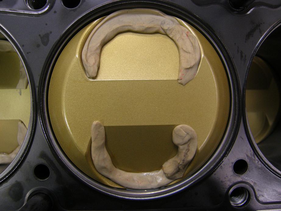
Finally I went all around the engine and set all the valves to zero lash, and then rotated the engine through several revolutions, to get a good impression in the clay of cylinders 2 through 8.  This whole process had taken me most of the day, but now I was really curious about what the clay looked like, so I spent another hour tearing the whole thing down.  Seems like this was a lot of work to go through to just check everything and time the cams, but that's what you have to do with these engines.  The clay held a lot of interest for me because on my 585" SOHC, I had seen piston to valve contact on about five of the cylinders, and none on the other three.  So I clayed everything in hopes of ferreting out any issue with the heads; maybe the valves were not spaced evenly in the heads or something.  But after pulling the heads all seven clayed cylinders looked alike, with the intake valve imprint right in the center of the piston's valve relief.  There was so much exhaust valve clearance that the valves didn't even hit the clay; here's a photo of one cylinder, showing the imprint from the intake valve:


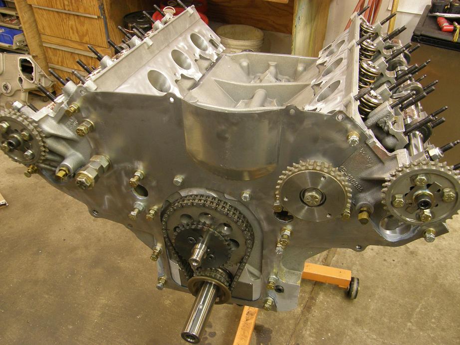
After taking a break I got back out to the shop tonight to start the assembly for real.  I pulled the checker springs off the number 1 valves and put the real valve springs on, then cleaned up the block and head mating surfaces and the head gaskets and bolted everything together.  I went a little heavy on the torque, 115 lb-ft on the long head studs and 105 lb-ft on the short head studs.  Then I got ready to start with the front cover backing plate.  The gasket situation for this piece is that there are five gaskets that go between the head and the block, and the backing plate.  Then, another five gaskets go between the backing plate and the front cover.  Finally there are two water pump gaskets that go between the front cover and the water pump.  If you were to try to put this all together at once, you would find that by the time you put the backing plate in place, assembled the chain drive, installed the front cover, then installed the water pump, and then tightened everything down, the sealer would have dried and you would have a bunch of leaks.  Ask me how I know this  ;D  Therefore, instead of doing this all at once, I do it in stages.  The first stage is to get the backing plate stuck to the block and heads.  I use a bunch of short bolts with nuts and washers on them to bolt the backing plate to the block and heads, and then let it sit overnight so that the sealer can cure.  I've been using a new sealer that Barry R turned me onto, a gray sealer from Ford that is a lot like The Right Stuff, but its gray instead of black, and comes in a caulk tube so you don't have to rely on the pressure in the sealer can (I've thrown away quite a few tubes of The Right Stuff where there is more sealer in the tube, but it just won't come out).  The sealer tube says Motorcraft RTV Silicone Sealant, for use on 7.3L Diesel Engines.  From the tube the part number appears to be TA-31.  I applied the sealer to the block and heads and stuck the five gaskets in place; here's a photo:


Then I put more sealer on the gaskets, and installed the cover plate.  The photo below shows the cover plate bolted in place with my temporary bolt arrangement, which bolts the plate firmly to the block and heads while the sealer is drying:


Now that the mockup is all done, P-V clearance is checked, and the cams are timed, the engine should go together without a lot of drama.  I hope to be able to finish assembly this week, and with luck be on the dyno with this engine next weekend.  I'll post more on the project later in the week.
Jay Brown
- 1969 Mach 1, Drag Week 2005 Winner NA/BB, 511" FE (10.60s @ 129); Drag Week 2007 Runner-Up PA/BB, 490" Supercharged FE (9.35 @ 151)
- 1964 Ford Galaxie, Drag Week 2009 Winner Modified NA (9.50s @ 143), 585" SOHC
- 1969 Shelby Clone, Drag Week 2015 Winner Modified NA (Average 8.98 @ 149), 585" SOHC


rcodecj

  • Sr. Member
  • ****
  • Posts: 474
    • View Profile
Re: 519" SOHC Build
« Reply #43 on: April 02, 2012, 09:52:02 AM »
The TA-31 is great stuff and I like it better than the Right Stuff. The best way I have found on either one when you are done using it is to leave one inch of squeezed out sealer and let it sit and dry.
It works better for me than what I used to do which is stuff a nail or wire into the end of the tube and cover it.

As far as gasket sealer on the water pump and timing cover, I have stopped using any sealer on them years ago.
My 460 timing cover, waterpump plate, waterpump, was a messy job using sealer and leaked. I tore it apart and used nothing and had no leaks.
My 390 is put together with no sealer on the timing cover or water pump and I have no leaks.
I got the idea from looking at how Ford does it on their crate motors on the 302's. They don't use sealer and they don't leak.
I also don't use any on the oil pan gasket except 4 small dabs for the timing cover to oil pan and rear main cap edge.
Lastly I quit using sealer on my 9" rearend pumpkins and no leaks anymore.

jayb

  • Administrator
  • Hero Member
  • *****
  • Posts: 7564
    • View Profile
    • FE Power
Re: 519" SOHC Build
« Reply #44 on: April 03, 2012, 11:54:08 AM »
Using no sealer is kind of a paradigm shift for me; I've always used it on pretty much any gasket except valve cover gaskets.  Typically for me, the valve cover gaskets are the ones that leak, although oil pan gaskets are close behind.  Anyway, with the SOHC you have that plate behind the front cover that tends to be a little wavy, kind of like a windage tray after it has been installed once, so I don't think I'd want to try to run without sealer on one of these engines.  Maybe I'll try it on a regular FE at some point...
Jay Brown
- 1969 Mach 1, Drag Week 2005 Winner NA/BB, 511" FE (10.60s @ 129); Drag Week 2007 Runner-Up PA/BB, 490" Supercharged FE (9.35 @ 151)
- 1964 Ford Galaxie, Drag Week 2009 Winner Modified NA (9.50s @ 143), 585" SOHC
- 1969 Shelby Clone, Drag Week 2015 Winner Modified NA (Average 8.98 @ 149), 585" SOHC