Author Topic: 519" SOHC Build  (Read 81720 times)

0 Members and 1 Guest are viewing this topic.

jayb

  • Administrator
  • Hero Member
  • *****
  • Posts: 7427
    • View Profile
    • FE Power
Re: 519" SOHC Build
« Reply #45 on: April 03, 2012, 01:30:54 PM »
I've been able to get more work done on assembly of this engine over the last couple of days.  After getting the backing plate glued into place, I started assembly on the timing components.  I put the chain tensioner in place in order to get the chain installed, so I could install the upper chain guide.  A photo of the tensioner is below, showing the top section of the tensioner where I brush some machinist's blue on the part.  You can see the grooves in this factory piece, showing where the chain has rubbed on it in the past.  I like to keep the chain tight enough so that you don't see this kind of rubbing, so with the machinist's blue dye on the top of the tensioner, you can pull the inspection plate on the right side of the front cover and look at the tensioner to see if there are any witness marks in the dye after the engine has run for a while.  If there are, I usually will tighten the chain tensioner bolt an eighth of a turn or so, re-mark the tensioner with dye, and then run the engine again and look for contact.  I just keep doing that until there is no contact between the chain and the tensioner during a dyno pull. 


After installing the tensioner I put the chain on, and then installed the upper chain guide.  Next I tightened the tensioner so that the slack was out of the chain; you don't want to go any tighter than absolutely necessary here, because the front cover is not yet installed and you don't want to pull too hard on the nose of the stub cam.  You just need to have enough tension so that the chain doesn't droop between the two cam gears.  Here's a photo of the guide installed before the chain was tightened:


The upper chain guide has to be adjusted so that its nylon rubbing blocks are just a whisker away from touching the chain, as shown in the photo below.  There are two bolts that hold the chain guide in place at either end, and the chain guide is slotted so it can be moved up and down with respect to the chain:


These chain guides are aftermarket units.  The rivets used to hold the nylon rubbing blocks to the sheet metal of the guide stick up from the top of the chain guide by a fair amount, and this will interfere with the front cover during installation.  Before installing the guilde you need to grind those rivets down a fair amount, as shown in the photo below:


Next you have to install the lower chain guide, but in order to do that you have to remove the tensioner arm, because the lower chain guide bolts are behind it.  Fortunately you really don't need the chain tight to install the lower chain guide.  The bolt holes in the lower chain guide are oversize so that it can be moved around a little bit; you need to try to make the lower chain guide nylon rubbing blocks parallel with the rubbing blocks of the upper chain guide.  Here's a photo of the lower chain guide installed:


Next I reinstalled the tensioner arm and snugged up the chain so it was close to its final position, and then started installing some of the other bolts.  On the right side there are two bolts that go into the block and the holes pass into the water jacket.  One of them is the lower water pump bolt, which goes on later, but the other is a bolt normally used for a stock FE timing cover, and this bolt is not accessible once the front cover is in place.  You don't want a leak here, so put sealer on the threads and also around the head of the bolt after it is tightened in place.  See the photo below; sorry for the poor quality:


For my engines I install supplemental oiling tubes to do a direct shot of oil onto the fuel pump gear bearing and the tensioner arm gear bearing.  I like to do this because these bearings are normally oiled only with splash, and at idle I don't think there's a lot of splash in this area.  Since my engines are all run on the street for extended periods, idling for long periods is required, so I like to provide supplemental oil.  On each side of the engine I tap into the front oil passage coming out of the head, and run a small inverted flare tube up to the bearing as a squirter.   I pinch the end of the tube so there is about a .010" orifice there, so only a small stream of oil will come out; you can see this during pre-oiling.  Here's a photo of the left side squirter tube close to its installation position, and then a shot of it from the side showing it pointing to the roller bearing behind the fuel pump gear; you have to oil this one from behind, because the gear blocks access to the bearing from the front:


Here's the same arrangement for the bearing in the tensioner arm, which can be oiled from the front:


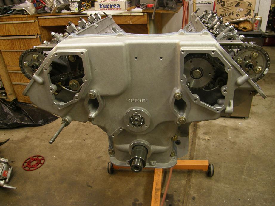
The photo below shows everything installed, ready for the front cover installation.  The two studs shown in the photo go into the block, and it is best to cut up a scrap piece of gasket and put it between the block and the backing plate before you tighten it in place, otherwise you will be trying to distort the backing plate and front cover a little when you tighten those bolts.  The small piece of gaskets basically spaces the backing plate out from the block the same as the normal gaskets between the block and heads, and the backing plate:


If you'd done everything right the front cover will then just slide into place along the two studs and over the stub cam nose.  Mine went together very smoothly.  This is a Pond front cover, and is an excellent piece compared to some of the other front covers that are available:


Note that the water pump is not yet installed, but the bolts are used with spacers to tighten the front cover against the gaskets between it and the backing plate.  At this point the stub cam is not yet in its final position; in order to pull it forward and install the snap ring, you need to put a bolt in the front of the stub cam and pull it forward with a pry bar, as shown in the photo below:


Last thing I did before calling it quits was to set the valve covers and the sheet metal intake with the Dominators that my friend Greg lent me to try out on the dyno, just to see how it would look:


I should be able to finish the engine up by the end of this week, then put it on the dyno on Saturday.  We'll see what happens...
« Last Edit: April 03, 2012, 06:18:52 PM by jayb »
Jay Brown
- 1969 Mach 1, Drag Week 2005 Winner NA/BB, 511" FE (10.60s @ 129); Drag Week 2007 Runner-Up PA/BB, 490" Supercharged FE (9.35 @ 151)
- 1964 Ford Galaxie, Drag Week 2009 Winner Modified NA (9.50s @ 143), 585" SOHC
- 1969 Shelby Clone, Drag Week 2015 Winner Modified NA (Average 8.98 @ 149), 585" SOHC


philminotti

  • Full Member
  • ***
  • Posts: 115
    • View Profile
Re: 519" SOHC Build
« Reply #46 on: April 03, 2012, 02:33:19 PM »
I love this thread, Jay.  Your supplemental oil squirters are fantastic!  Thanks for sharing.

Phil

fetorino

  • Full Member
  • ***
  • Posts: 150
  • Tunnelport Cobra
    • View Profile
Re: 519" SOHC Build
« Reply #47 on: April 03, 2012, 11:01:08 PM »
I can't wait to see it on the dyno.  I know way more about SOHC timing chains than I ever thought I would.  The oil sprayers remind me of the Suzuki GSXR motors and their air oil cooling.

66FAIRLANE

  • Hero Member
  • *****
  • Posts: 564
  • Andy
    • View Profile
Re: 519" SOHC Build
« Reply #48 on: April 04, 2012, 01:47:15 AM »
Fantastic thread. I really hope I get to build one of these one day. Thanks for sharing Jay.

And as for: "Last thing I did before calling it quits was to set the valve covers and the sheet metal intake with the Dominators that my friend Greg lent me to try out on the dyno, just to see how it would look"

I'd say, it looks freakin awesome!

jayb

  • Administrator
  • Hero Member
  • *****
  • Posts: 7427
    • View Profile
    • FE Power
Re: 519" SOHC Build
« Reply #49 on: April 06, 2012, 04:51:18 PM »
Got finished up with the assembly of the engine tonight.  I should be able to get it on the dyno tomorrow, but I don't know if I'll actually get any running in because I have family obligations for part of  tomorrow, and of course Sunday is Easter, so I don't know if I want to subject the neighborhood to 7500 RPM cammer pulls on Easter Sunday LOL!  We'll see what happens.  One thing that happened this week which was a bit of a disappointment was that I wasn't able to fit the sheet metal intake on the engine.  I had forgotten about that when I changed my plans and went to the high port heads.  This change requires a spacer plate between the intake and the head on each side, and the intake manifold bolt holes have to be slotted so that the manifold will still fit.  I got ready to fit the sheet metal intake on the engine and the intake bolt holes weren't even close.  This is not my manifold, so slotting it to make it fit wasn't in the cards, so I went straight to the Hilborn intake instead.  Too bad, because I'll bet the engine would make more power with the sheet metal manifold.  Oh well...

Here's some photos of the engine going together, including a shot of the valvetrain on one side, a shot with the engine upside down on the stand (I always liked that view for some reason), the front components, and a couple of photos of the completed engine on the stand.  I'll post more when I have some dyno data to share.


Jay Brown
- 1969 Mach 1, Drag Week 2005 Winner NA/BB, 511" FE (10.60s @ 129); Drag Week 2007 Runner-Up PA/BB, 490" Supercharged FE (9.35 @ 151)
- 1964 Ford Galaxie, Drag Week 2009 Winner Modified NA (9.50s @ 143), 585" SOHC
- 1969 Shelby Clone, Drag Week 2015 Winner Modified NA (Average 8.98 @ 149), 585" SOHC


rcodecj

  • Sr. Member
  • ****
  • Posts: 474
    • View Profile
Re: 519" SOHC Build
« Reply #50 on: April 06, 2012, 04:59:51 PM »
I noticed the water pump pulley has counter sunk bolts. Is there a reason for that, to clear something maybe?
Looks good!

ToddK

  • Sr. Member
  • ****
  • Posts: 437
    • View Profile
Re: 519" SOHC Build
« Reply #51 on: April 06, 2012, 06:56:01 PM »
Looking god Jay, I'd love to hear that sing. Would be the sort of music I would like to hear on an Easter Sunday.

machoneman

  • Hero Member
  • *****
  • Posts: 3855
    • View Profile
Re: 519" SOHC Build
« Reply #52 on: April 06, 2012, 07:02:29 PM »
Oh so cool Jay! Hey, screw those neighbors I say!

Just kidding.

Yah know, I don't care how much better the coil-on-plug ignition is but seeing the clean lines of that traditional SOHC look is truly inspiring.
Bob Maag

cdmbill2

  • Jr. Member
  • **
  • Posts: 87
    • View Profile
Re: 519" SOHC Build
« Reply #53 on: April 06, 2012, 07:41:34 PM »
Countersunk bolt heads on the water pump pulley are cosmetic at least they were on March stuff. If you are running a mechanical fan then tey would be replaced.

jayb

  • Administrator
  • Hero Member
  • *****
  • Posts: 7427
    • View Profile
    • FE Power
Re: 519" SOHC Build
« Reply #54 on: April 06, 2012, 08:02:48 PM »
Yes, I don't recall countersinking them for any reason, they probably came that way from March...
Jay Brown
- 1969 Mach 1, Drag Week 2005 Winner NA/BB, 511" FE (10.60s @ 129); Drag Week 2007 Runner-Up PA/BB, 490" Supercharged FE (9.35 @ 151)
- 1964 Ford Galaxie, Drag Week 2009 Winner Modified NA (9.50s @ 143), 585" SOHC
- 1969 Shelby Clone, Drag Week 2015 Winner Modified NA (Average 8.98 @ 149), 585" SOHC


rcodecj

  • Sr. Member
  • ****
  • Posts: 474
    • View Profile
Re: 519" SOHC Build
« Reply #55 on: April 07, 2012, 01:53:15 PM »
That's interesting on the countersinking. I have had many sets of March pullies including FE, 460, and small block, and I have never seen that.

jayb

  • Administrator
  • Hero Member
  • *****
  • Posts: 7427
    • View Profile
    • FE Power
Re: 519" SOHC Build
« Reply #56 on: April 08, 2012, 08:50:49 PM »
Maybe I did countersink them, but just forgot that I did it.  I can think of one potential reason why; the supercharger belt on my 489" supercharged engine comes pretty close to the front of the water pump pulley.  Maybe I countersunk those bolts to gain some clearance there.  I don't remember doing it, but it would have been in 2005 or 2006, so I could easily have forgotten about it...
Jay Brown
- 1969 Mach 1, Drag Week 2005 Winner NA/BB, 511" FE (10.60s @ 129); Drag Week 2007 Runner-Up PA/BB, 490" Supercharged FE (9.35 @ 151)
- 1964 Ford Galaxie, Drag Week 2009 Winner Modified NA (9.50s @ 143), 585" SOHC
- 1969 Shelby Clone, Drag Week 2015 Winner Modified NA (Average 8.98 @ 149), 585" SOHC


jayb

  • Administrator
  • Hero Member
  • *****
  • Posts: 7427
    • View Profile
    • FE Power
Re: 519" SOHC Build
« Reply #57 on: April 08, 2012, 09:18:15 PM »
It was quite the struggle on the dyno this weekend.  I didn't get going on getting the engine installed on the dyno until Saturday afternoon, and it took a while to get everything hooked up.  Mostly I struggled with the EFI system, which is a FAST system.  It has an unbelievable number of wires and connectors, most of which you don't need, and there is also some custom wiring required for the distributor and crank sensor.  This setup uses a FAST distributor with the crank signal from the distributor disabled, in favor of the crank trigger.  The cam signal from the distributor is enabled though. allowing for full sequential operation.  I always liked this particular feature of the FAST setup, but there's a lot of special stuff you have to do to make it work.  After I finally worked through the rats nest of wiring I was ready to fire the engine at six o'clock Saturday night.  Unfortunately, no joy; the engine would not even kick.  I spent an hour looking at all the crank trigger and distributor wiring trying to find a problem, and finally when I started moving one particular bundle of wires around I heard some noise coming from the front of the engine.  Turns out it was the coil, and apparently it was trying to fire when I moved the wires.

I traced the problem to the wire harness leading into the distributor.  Pulling the wires up into the distributor itself, I could see that two of the wires had been rubbing on the distributor body and had worn through, shorting to the body when the cable was pulled on.  I taped up these areas, still hoping to get the engine fired before 8:00, but still no joy.  This time it seemed that the engine wasn't getting fuel for some reason.  At that point I called it a day on Saturday, and spent the rest of the evening reading my FAST manual and looking at the schematic to see if I had missed something along the way.

Today when I got back out to the shop I decided to slow down a little and check everything more carefully.  I found again that I was able to trigger the coil by pulling just right on the distributor cable; apparently my quick fix hadn't worked.  I pulled the distributor out of the engine and fixed it correctly, plus I sleeved the cable going through the distributor housing so it wouldn't do this again.  After the distributor was reinstalled and the cam sensor and crank sensor timing double checked, I tried to start the engine again but still no luck.  Again it was fairly clear that the engine wasn't getting fuel.  I checked the fuse and the relay for the injectors, messed with the cranking fuel table and throttle position sensor calibration in the FAST software, and did several other things trying to resolve this problem, but no luck.  Finally I resorted to dumping some fuel into the injector stacks and cranking the engine.  With one cough it fired right up and ran for three seconds until it was out of fuel.  At least I knew for sure what the problem was.

I called my pal Scott Clark on this, and he gave me some pretty good suggestions.  One was to swap out the FAST EFI box itself with my spare; I did that, but there was no change.  Scott also suggested disconnecting the injector wiring harness and checking the voltages going to the injectors to see if I had voltage there.  Sure enough, there was voltage for each injector, and it decrease when the injectors were pulsing as the engine cranked.  Everything looked good there.

Scott's last suggestion was to pull the injectors and check them, and this turned out to be the problem.  I've never dealt with this before, but these particular injectors have been on the shelf for about four years, and apparently sometimes injectors will stick when left dry like this.  Four injectors did not click when I removed them from the engine and applied 12 volts to their terminals.  Three came around with repeated applications of 12V, but one of them had to be smacked a couple of times with a screwdriver before it loosed up and starting clicking with voltage.  I cycled all the injectors several times and cleaned them out as best as I could, then reinstalled them in the engine.  By this time it was after 6:00, and I had to go in for dinner with the family, but just before 7:30 I got back out to the shop to try the engine.  I cranked it up and...  nothing.  What the hell?  However, when I went into the dyno room to look at the engine, I saw that my coil trigger wires had come loose from the MSD when I was removing and replacing the injectors.  I figured this was the problem, so I reconnected them, but now I had an engine full of fuel.  Sure enough, when I cranked the engine this time it fired right up and revved to over 3000 RPM.  For about one and half seconds I was really happy, then the oil filter deformed and blew off the motor, spraying oil all over the dyno room.  Sheesh, if its not one thing its another.  The filter was a Napa Gold filter, which I've had good luck with, but I guess I'm going to have to go back to those heavy duty Mobil 1 filters.

Anyway, now that I knew the engine would start most of the drama had gone out of the day.  I cleaned up the oil and replaced the filter, and a little more gingerly this time I fired up the engine.  I warmed it up to operating temperature while doing some minor tuning, and then shut it down so I could lash the valves hot.  One thing I noticed was that the engine has really excessive oil pressure.  I don't know why this is; even idling at 1000 RPM hot the oil pressure is around 60 psi, and when revving it up it will go to over 120 psi.  This is the same oil pump I've used in the past, and it never behaved this way before.  I'm thinking that maybe the bypass is stuck or something, which would be bad, because pulling the pan off this engine on the dyno stand would be no fun at all.  I'm hoping that with a little use it frees itself up.

In any case it looks like I can get to tuning this thing now, and if the oil pressure situation works itself out I should be able to get some dyno data by next Saturday, or maybe sooner.  I will post more info on this engine when I have it.
Jay Brown
- 1969 Mach 1, Drag Week 2005 Winner NA/BB, 511" FE (10.60s @ 129); Drag Week 2007 Runner-Up PA/BB, 490" Supercharged FE (9.35 @ 151)
- 1964 Ford Galaxie, Drag Week 2009 Winner Modified NA (9.50s @ 143), 585" SOHC
- 1969 Shelby Clone, Drag Week 2015 Winner Modified NA (Average 8.98 @ 149), 585" SOHC


ScotiaFE

  • Hero Member
  • *****
  • Posts: 1409
  • Howie
    • View Profile
Re: 519" SOHC Build
« Reply #58 on: April 09, 2012, 12:29:19 PM »
Great Stuff as usual!
Interesting about that filter. I was just in NAPA the other day and picked up a NAPA Gold.
It does not look like the Gold of just last year.
Kind of a cheesier paint job. It just didn't look as good as the old NAPA Gold "black one with NASCAR logo".
Hmmm.... Maybe I won't use it now?
I'll post some pics of the old and new.

Hemi Joel

  • Sr. Member
  • ****
  • Posts: 497
    • View Profile
Re: 519" SOHC Build
« Reply #59 on: April 09, 2012, 12:42:04 PM »
Jay, that's frustrating when all that stuff happens. At least you can try to find all the problems on the dyno, rather than  after the motor is bolted in the car.

After seeing the assembly proccess on your Cammer, I find it ironic that your URL name is simplemachinesforum. ;D