Author Topic: Billet Sheet Metal Style Intake Manifold for the FE Intake Adapter  (Read 31595 times)

0 Members and 1 Guest are viewing this topic.

jayb

  • Administrator
  • Hero Member
  • *****
  • Posts: 7404
    • View Profile
    • FE Power
Since the previous post on this topic ( http://fepower.net/simplemachinesforum/index.php?topic=2402.0  ), I've been doing a lot of research on sheet metal style intakes.  Based on the poll in the previous thread, it appeared that this type of intake was of the highest interest, and without a good alternative available for the FE (except for my intake adapter + the 351C tunnel ram), I thought it would be best to pursue this manifold option first.

My original plan had been to do a design that could be cast in aluminum to minimize cost for the manifold.  However, a couple things changed my mind about that.  First, after digging pretty deep into sheet metal intake design, it became clear that one design would definitely not fit all.  I suppose that's why the sheet metal intake companies like Hogan are in business; depending on your RPM range and the duration of your camshaft, the ideal intake will vary quite a bit in runner length, plenum volume, runner taper, etc.  Tooling up a casting was going to be expensive, and I couldn't really afford to tool up several of them to meet a variety of different requirements.  Second, working with the foundries has been very frustrating in terms of delivery time.  I'm a pretty small fish to these companys, not part of the customer base that keeps them in business, and I've had to tolerate some significant delays in delivery of my parts, because I don't get a lot of priority. This has led to delays in making my intake adapters available, which is frustrating for me, and also for the people on the list to receive them.

So, I got to thinking - What if I just machined the manifold from billet?  It would be more expensive that way, but there would be no big tooling costs to bear, and no minimum production run required to justify the tooling expense.  Plus I could do several variations of the manifold by just changing the design and machining different parts out of billet.  And I wouldn't be subject to any foundry delays, because billet aluminum in the sizes I was looking at is readily available locally.

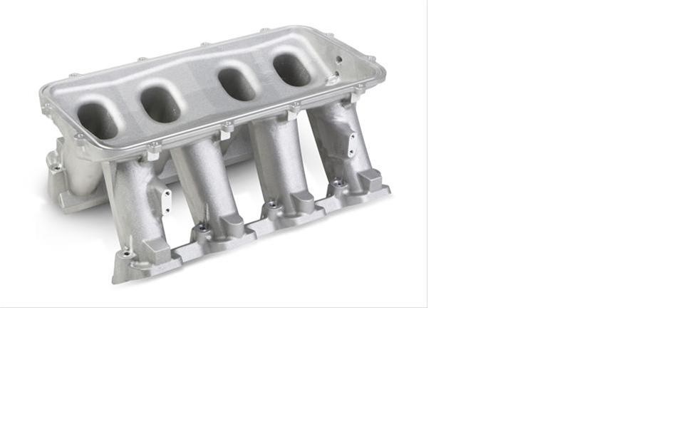
One thing that helped move me along in this direction was availability of some parts from Holley that could be adapted to this project.  Holley makes an intake manifold for the LS engine with several different upper plenum types available.  The manifold base contains the lower part of the plenum, and they offer several upper plenums, to mount carbs or throttle bodies depending on the application.  Here are some pictures of what Holley makes available.  First, a picture of the manifold base:


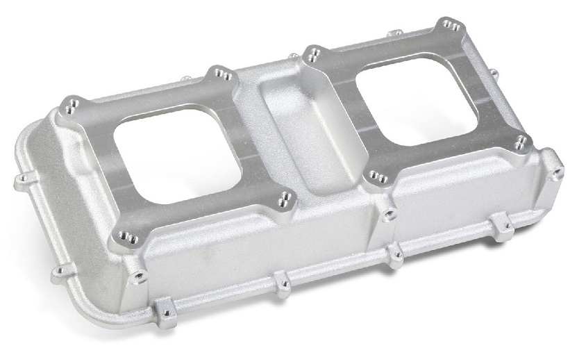
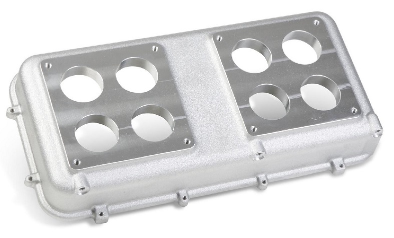
Next, here are three of the upper plenums that are available.  There is also a fourth upper plenum available that is blank, and can be machined for a custom application:


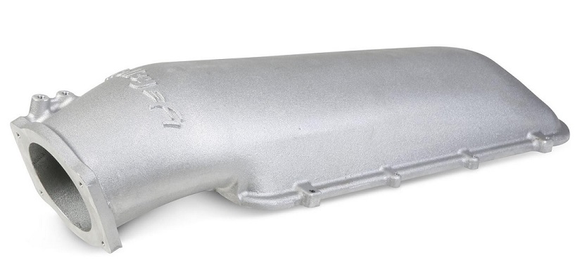
Finally, they make this spacer available, allowing you to increase plenum volume by adding spacers between the manifold base and the upper plenums:


The upper plenums and spacers seal to the manifold base with a big O-ring, kind of like I seal the center plate of my intake adapter to the adapter itself.  So, you can bolt together whatever plenum you want, and change plenum volume for your application by adding spacers.

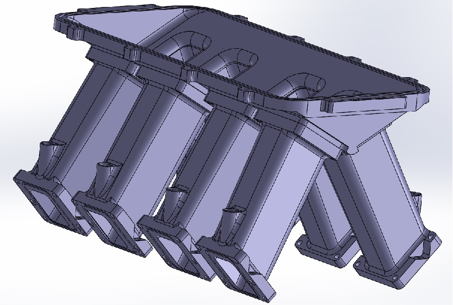
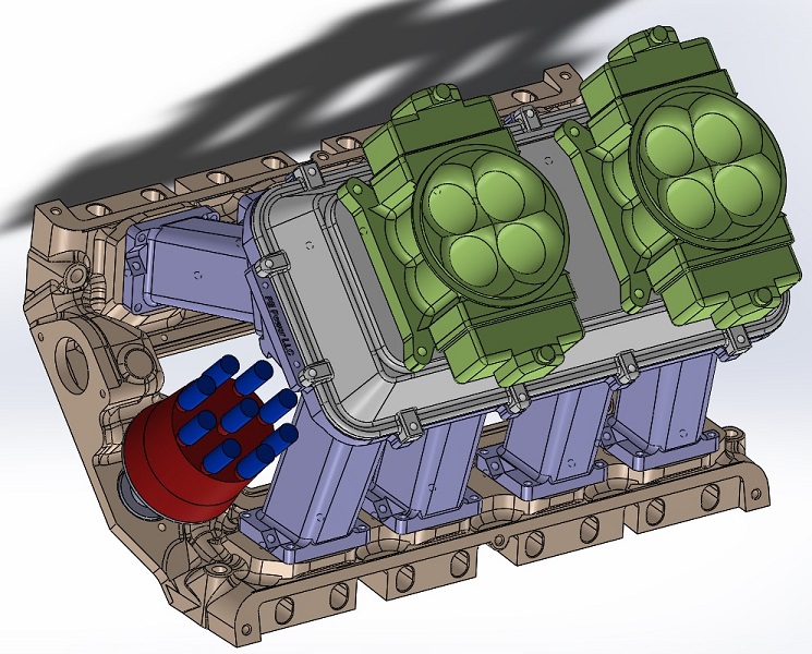
I got going in January working with Solidworks, and after going through a book full of tutorials I started to design the parts for this project.  I've completed a carbureted and fuel injected version of the first manifold so far.  The runner length is designed to tune at 6800 RPM using the third harmonic, with a power band from 6400 to 7300.  Here's a couple screen captures of the manifold from the Solidworks design file:


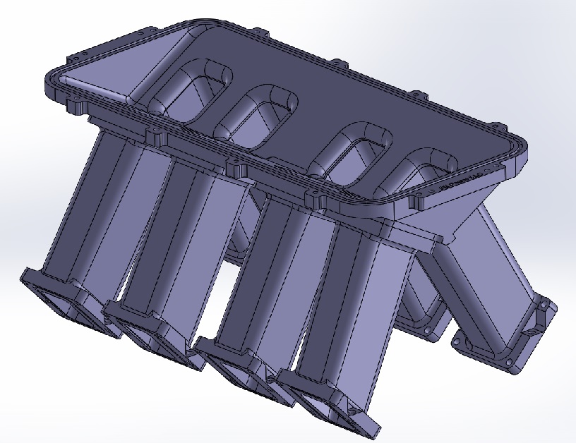
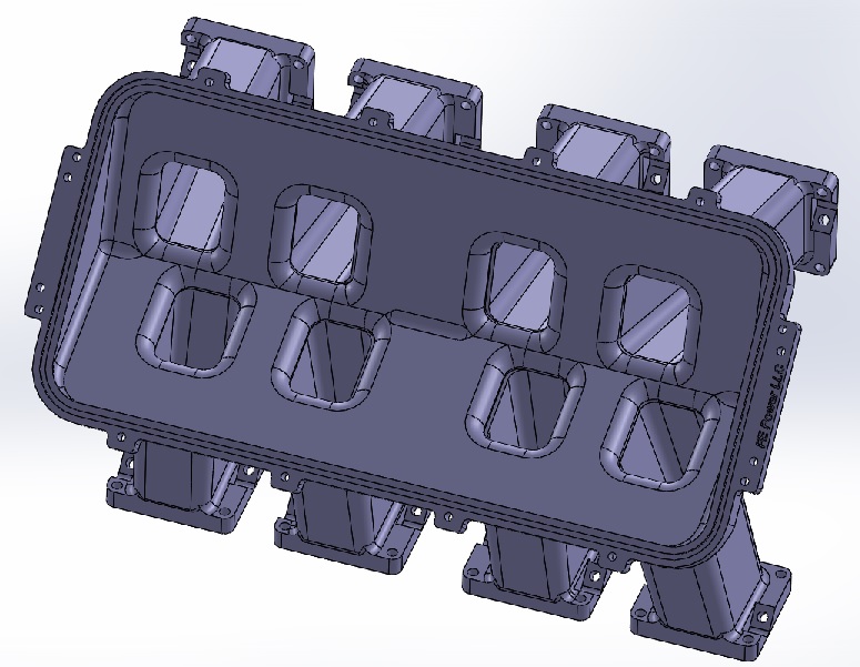
All 8 runners are machined individually using this approach.  There are four distinct runners, duplicated on  both sides of the manifold.  They bolt to the lower plenum, using O-rings for sealing.  The lower plenum is designed to accept the upper plenums available from Holley.  The runners also have O-ring grooves in the bottom, to seal to the intake adapter:


Notice that on the inboard sides and tops of the runners, there is a lot of room between the O-ring groove and the machined port.  This is to allow for some porting if desired.  Usually when you increase the size of the FE port, you make it wider on the inboard side to straighten it, and raise it at the top for a better shot at the valve.  The runners are designed to allow porting in this direction, and there is extra meat in the runners all the way to the top for this.

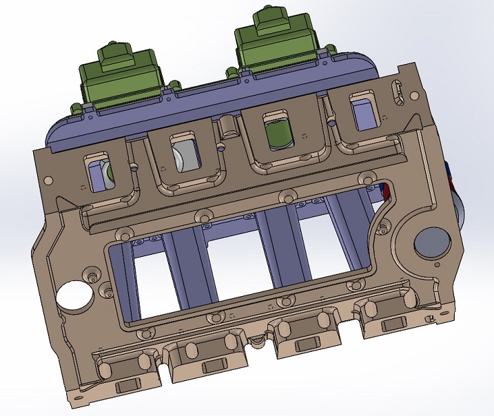
The screen shot below shows the manifold from the front.  You can see that the runners come out of the intake adapter at a bit of an angle. 


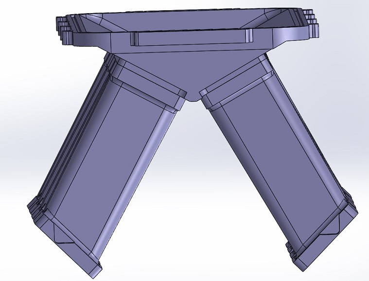
The reason for this is that if they came straight out, the runner length would be shorter, and the RPM that this manifold would tune at would go up quite a bit.  To make this a smooth intake tract, I have designed the ports in the intake adapter to swoop upward a little bit, allowing a smooth transition to the stock FE port.

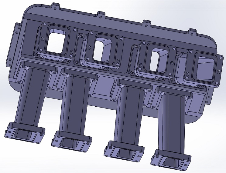
Here's the same manifold, but with runners that include a boss for a fuel injector:


One downside to the fuel injector version of this design is that you have to start with a larger chunk of billet aluminum to machine it.  I can get the standard runners fit into a 3" X 4" cross section, but after adding the fuel injector boss I have to go to a 4" X 4" billet, which is quite a bit more expensive.  So, the EFI versions will be more expensive than the carbureted version of this intake manifold.

Of course I didn't start from scratch with this design, I had to make it fit on the intake adapter first.  When I first got going on the intake adapter project, I had no experience with Solidworks, so I had another guy do the design for me.  It took forever and cost a bunch, and then the pattern shop had to redo it before it was acceptable for generating the tooling, but finally I got a model that worked.  I took this model, removed the FE to 351C ports, and put in some different porting to fit this manifold, then designed the runners and lower plenum from there.  After I got done with that I drew up one version of the Holley plenum top, plus an MSD distributor and a couple of Holley 4150 carbs.  The carbs are not very accurate, except for placement of the throttle bores and mounting holes, but I wanted to get an idea of what the whole induction system would look like.  Here's a few screen shots:


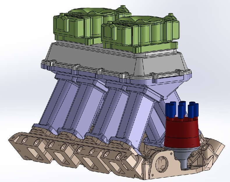
In the last shot, you can see the vertical bolt holes in the front of the runners.  There is a matching hole on the opposite side of each runner, so that two bolts hold each runner in position on the intake adapter.  The other four holes in the bottom of each runner are only used to hold the runner during the machining operations. I wanted to use a vertical bolt to hold the manifold to the intake adapter, because the O-rings will stand a little proud of the mating surface, and trying to put a bolt in at an angle might be problematic.  Using the vertical bolts will allow the manifold to pull straight down onto the intake adapter, and compress the O-rings evenly.

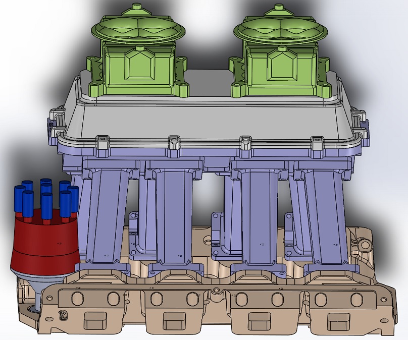
Next I decided to do an EFI version, so I did models of the fuel rails, fuel injectors, and fuel rail brackets.  I put the front facing upper plenum on this one; here's a screen shot:


I don't think this one will fit under the hood, but I'm planning another version that uses shorter runners (and no upward curve in the intake adapter) to tune to the fourth harmonic at 6800 RPM, rather than the third harmonic.  As I understand it, the fourth harmonic will not yield the same high torque as the third harmonic does, but the tuning range is a little wider, maybe 1400 RPM instead of around 1000 RPM.  The objective here would be to get the overall height low enough so that it would fit under a stock hood. 

I'm also looking at doing a version with shorter runners that tunes at the third harmonic, around 8000 RPM.  Maybe the Super Stock guys would like that one.

Finally, I'm also thinking of a version that would bolt onto the existing 13001 intake adapters, with the 351C 4V ports.  The adapter would have to be drilled and tapped for the vertical mounting holes to mount the intake manifold, and this version would not get rid of the angle in the #1, #4, #5, and #8 ports that you get from adapting the FE to a Cleveland intake, but I think it would work as well or better than the Weiand tunnel ram.  And it would look cooler  ;D

When designing these parts I had to figure out how I was going to fixture them and machine them, and without going into any detail, I think I have that figured out.  I should be able to machine all four runners for one side at the same time, using two different setups on my fourth axis CNC machine table.  Keeping the number of setups down lowers the time I have to spend working on the parts, and so reduces the costs.

Speaking of costs, the billet aluminum required for the carbureted version of the intake is around $480.  Add in the cost of the O-rings and the hardware and you are pretty close to $500.  I think I can machine them for another $500, so selling price would be about $1000.  But you have to consider that you will need an intake adapter ($549), plus an upper plenum ($160), and Holley doesn't give the plenum spacers away either ($110).  For the EFI version you would have more material cost, adding probably $125 to the price.  Plus I would probably offer machined fuel rails and fuel rail brackets for another couple hundred bucks, to make the whole package easier to install.

So, my question, and the reason for the post, is this:  Is this too expensive to be attractive?  It would certainly be a lot cheaper than a Hogan manifold, but its still not cheap.  I appreciate any responses to this post, especially if you might be interested in one of these setups, if/when I make them available.  Thanks, Jay
« Last Edit: March 05, 2015, 09:41:43 PM by jayb »
Jay Brown
- 1969 Mach 1, Drag Week 2005 Winner NA/BB, 511" FE (10.60s @ 129); Drag Week 2007 Runner-Up PA/BB, 490" Supercharged FE (9.35 @ 151)
- 1964 Ford Galaxie, Drag Week 2009 Winner Modified NA (9.50s @ 143), 585" SOHC
- 1969 Shelby Clone, Drag Week 2015 Winner Modified NA (Average 8.98 @ 149), 585" SOHC


fastback 427

  • Sr. Member
  • ****
  • Posts: 442
    • View Profile
Re: Billet Sheet Metal Style Intake Manifold for the FE Intake Adapter
« Reply #1 on: March 05, 2015, 05:32:27 PM »
First, very very cool. So about 2 grand or so? How would these parts work with supercharging?  For instance blow thru setups seem to be limited to about a thousand HP, the ez efi kits aren't recommended for supercharging. Can someone build their own f.I.system like the L s  flaps have or the 5.0 crowd , and make 1500hp plus with a procharger or turbos?
Jaime
67 fastback 427 center oiler 428 crank Dove aluminum
top end toploader
67 fairlane gta cross bolted 12:1 390 Dove aluminum top end c6 3600 stall
65 falcon straight axle project
67 mustang coupe project
76 f350 dually 390 mirror 105 4bbl 4spd
74 f100 xlt 390 c6 factory ac

ScotiaFE

  • Hero Member
  • *****
  • Posts: 1409
  • Howie
    • View Profile
Re: Billet Sheet Metal Style Intake Manifold for the FE Intake Adapter
« Reply #2 on: March 05, 2015, 06:24:39 PM »
That looks friggin super kool Jay!
That's a lot of whittling for 500 bucks. I may just have to get in line on that deal. ;D

jayb

  • Administrator
  • Hero Member
  • *****
  • Posts: 7404
    • View Profile
    • FE Power
Re: Billet Sheet Metal Style Intake Manifold for the FE Intake Adapter
« Reply #3 on: March 05, 2015, 06:29:59 PM »
For a high horsepower turbo or supercharged engine, manifolds like this work fine.  It would be no problem to do the EFI system, you've just got to use one of the more tunable ones, rather than the "tunes itself" variety.  I have a couple of T-80 turbos that I was going to use on one of my SOHC engines, figured on 1800 HP.  I was going to build a sheet metal intake for the SOHC like the ones shown in my post, and then use a Megasquirt MS3X or MS-Pro EFI system to run it.
Jay Brown
- 1969 Mach 1, Drag Week 2005 Winner NA/BB, 511" FE (10.60s @ 129); Drag Week 2007 Runner-Up PA/BB, 490" Supercharged FE (9.35 @ 151)
- 1964 Ford Galaxie, Drag Week 2009 Winner Modified NA (9.50s @ 143), 585" SOHC
- 1969 Shelby Clone, Drag Week 2015 Winner Modified NA (Average 8.98 @ 149), 585" SOHC


mike7570

  • Guest
Re: Billet Sheet Metal Style Intake Manifold for the FE Intake Adapter
« Reply #4 on: March 05, 2015, 07:58:27 PM »
How far off is the runner spacing for the Holley LS stuff from your intake adapter.  Could another adapter between them work?
Could be a lot less expensive but I don't know any of the dimensions
« Last Edit: March 05, 2015, 08:02:43 PM by mike7570 »

jayb

  • Administrator
  • Hero Member
  • *****
  • Posts: 7404
    • View Profile
    • FE Power
Re: Billet Sheet Metal Style Intake Manifold for the FE Intake Adapter
« Reply #5 on: March 05, 2015, 08:11:53 PM »
The side to side stagger on the LS manifolds won't work.  The left bank of the engine is farther forward than the right bank, opposite to the FE.
Jay Brown
- 1969 Mach 1, Drag Week 2005 Winner NA/BB, 511" FE (10.60s @ 129); Drag Week 2007 Runner-Up PA/BB, 490" Supercharged FE (9.35 @ 151)
- 1964 Ford Galaxie, Drag Week 2009 Winner Modified NA (9.50s @ 143), 585" SOHC
- 1969 Shelby Clone, Drag Week 2015 Winner Modified NA (Average 8.98 @ 149), 585" SOHC


482supersnake

  • Guest
Re: Billet Sheet Metal Style Intake Manifold for the FE Intake Adapter
« Reply #6 on: March 05, 2015, 08:21:14 PM »
Looks cool. After that you can start on one like this. ;D ;D ;D


http://thefactoryfiveforum.com/showthread.php?7504-351w-intake-manifold-height

jayb

  • Administrator
  • Hero Member
  • *****
  • Posts: 7404
    • View Profile
    • FE Power
Re: Billet Sheet Metal Style Intake Manifold for the FE Intake Adapter
« Reply #7 on: March 05, 2015, 08:34:48 PM »
That's cool, alright.  Unfortunately I've only got a 4 axis CNC machine, and at first glance it looks like a manifold like the one in your pictures would require a five axis CNC to machine. 
Jay Brown
- 1969 Mach 1, Drag Week 2005 Winner NA/BB, 511" FE (10.60s @ 129); Drag Week 2007 Runner-Up PA/BB, 490" Supercharged FE (9.35 @ 151)
- 1964 Ford Galaxie, Drag Week 2009 Winner Modified NA (9.50s @ 143), 585" SOHC
- 1969 Shelby Clone, Drag Week 2015 Winner Modified NA (Average 8.98 @ 149), 585" SOHC


ToddK

  • Sr. Member
  • ****
  • Posts: 437
    • View Profile
Re: Billet Sheet Metal Style Intake Manifold for the FE Intake Adapter
« Reply #8 on: March 05, 2015, 09:15:13 PM »
Jay, I'd definitely be in for a manifold. That is exactly like what I plan to run on my race engine with the HR intake adapter. You could put my name down now for one. I could also use it on my back up engine, for which I have a MR intake adapter.

You mentioned that you would be able to somewhat tune the runner length to suit hp rpm range, I'm looking at making peak power at in the 7000-7500rpm range out of a 490 cube engine. I guess that would entail a slightly shorter runner length?

jayb

  • Administrator
  • Hero Member
  • *****
  • Posts: 7404
    • View Profile
    • FE Power
Re: Billet Sheet Metal Style Intake Manifold for the FE Intake Adapter
« Reply #9 on: March 05, 2015, 09:30:21 PM »
Yes, it would make for a shorter runner.  Also with the high riser ports being higher on the face of the cylinder head, it ought to require less of a tilt up for the runner, maybe no tilt at all.  Should be a nice package.  Thanks for the positive feedback Todd, I'll keep you in mind on this.  If I can get interest from a dozen or so folks I'll get going on these as soon as I'm caught up on the intake adapters - Jay
Jay Brown
- 1969 Mach 1, Drag Week 2005 Winner NA/BB, 511" FE (10.60s @ 129); Drag Week 2007 Runner-Up PA/BB, 490" Supercharged FE (9.35 @ 151)
- 1964 Ford Galaxie, Drag Week 2009 Winner Modified NA (9.50s @ 143), 585" SOHC
- 1969 Shelby Clone, Drag Week 2015 Winner Modified NA (Average 8.98 @ 149), 585" SOHC


turbohunter

  • Hero Member
  • *****
  • Posts: 2509
    • View Profile
Re: Billet Sheet Metal Style Intake Manifold for the FE Intake Adapter
« Reply #10 on: March 06, 2015, 09:00:06 AM »
My FE experience isn't quite up to that speed yet but I could set it on my coffee table and stare at it for a while. ;)
Marc
'61 F100 292Y
'66 Mustang Injected 428
'66 Q code Country Squire wagon


cjshaker

  • Hero Member
  • *****
  • Posts: 4458
    • View Profile
Re: Billet Sheet Metal Style Intake Manifold for the FE Intake Adapter
« Reply #11 on: March 06, 2015, 11:17:56 AM »
The side to side stagger on the LS manifolds won't work.  The left bank of the engine is farther forward than the right bank, opposite to the FE.

Since the upper plenum isn't one piece with the lower, can the manifold be flipped around to counter the stagger, then just flip the upper to point in the right direction? It would require the upper plenums bolt pattern to be symmetrical, and I don't know if that's the case. Just thinking out loud.

As for the design itself, the redesigned adapter ports would require one of your intakes, severely limiting the choices. That's a big drawback to the advantage of the adapter in the first place, so interest would be limited to specific combos. I don't think I would want to go that route when I could custom make an upper to fit the standard lower, and keep many more options open as to the use of the adapter. Coming up with a minimum 100 people might be tough because of that limiting of choices. I'm not putting down the design, I think it's great, that's just part of the reality of it. For guys wanting to maximize power potential in race cars, it may be a more serious consideration. But I wasn't aware that any Stock or Super Stock racers could use an intake other than a factory type design, but I'm no expert on their rules either.

Would the close proximity of the plenums ports cause issues with distribution? It seems to me that most high end manifolds have them separated more, even if they have to use curved runners to achieve that. Curved runners was my first thought, but that would probably require going to the larger billet, thereby increasing cost.
Doug Smith


'69 R-code Mach 1, 427 MR, 2x4, Jerico, 4.30 Locker
'70 F-350 390
'55 Ford Customline 2dr
'37 Ford Coupe

jayb

  • Administrator
  • Hero Member
  • *****
  • Posts: 7404
    • View Profile
    • FE Power
Re: Billet Sheet Metal Style Intake Manifold for the FE Intake Adapter
« Reply #12 on: March 06, 2015, 12:52:00 PM »
The side to side stagger on the LS manifolds won't work.  The left bank of the engine is farther forward than the right bank, opposite to the FE.

Since the upper plenum isn't one piece with the lower, can the manifold be flipped around to counter the stagger, then just flip the upper to point in the right direction? It would require the upper plenums bolt pattern to be symmetrical, and I don't know if that's the case. Just thinking out loud.

As for the design itself, the redesigned adapter ports would require one of your intakes, severely limiting the choices. That's a big drawback to the advantage of the adapter in the first place, so interest would be limited to specific combos. I don't think I would want to go that route when I could custom make an upper to fit the standard lower, and keep many more options open as to the use of the adapter. Coming up with a minimum 100 people might be tough because of that limiting of choices. I'm not putting down the design, I think it's great, that's just part of the reality of it. For guys wanting to maximize power potential in race cars, it may be a more serious consideration. But I wasn't aware that any Stock or Super Stock racers could use an intake other than a factory type design, but I'm no expert on their rules either.

Would the close proximity of the plenums ports cause issues with distribution? It seems to me that most high end manifolds have them separated more, even if they have to use curved runners to achieve that. Curved runners was my first thought, but that would probably require going to the larger billet, thereby increasing cost.

Doug, if you flip the LS manifold around, you'll have the same problem with stagger.

On the adapter, do you mean the custom ports required for this manifold would limit the options for the intake adapter itself, to just this manifold?  I would agree with that, but I also plan to do one of these designs to fit the standard 351C 4V ports that are in the standard #13001 adapter.  The reason someone might want to go with the dedicated version is that it would eliminate the angle in the #1, #4, #5, and #8 ports found in the #13001 adapter.  Also, just to be clear, I don't need to make some large minimum number of these manifolds to cover tooling costs.  There aren't any tooling costs for this design; it uses the standard intake adapter casting that I've already tooled; I just have to machine a different port program into it.  And since there are no cast components of the intake manifold itself, the costs are in the billet aluminum that is required.  I will cover that with the price of each manifold.  I do have to write the CNC programs to machine these, but I'm figuring if I could sell 10 of them I could justify doing that.

I think the ports in the plenum are kind of a tradeoff.  You would like the runners to provide as straight a shot to the port as possible, but you would also like to have them open directly under the carb butterflies.  The primary issue for this design, though, was clearance to the distributor.  Because of that issue, the #5 runner has to bend towards the back of the engine.  I could have made that the only runner that does that, but I thought it would be better from a symmetry standpoint to make all four end runners symmetrical.  In addition, if I made all the runners on the right bank straight, the lower plenum would be too long to fit the Holley LS upper plenums.  The options were really to bend #4 and #5, and make all the rest straight, or to bend the outboard runners, and make the inboard runners straight.  So I made the #2, #3, #6, and #7 runners straight, while the remaining four runners are all angled like #5.  They do line up better with the carb butterflies this way. 

I actually started off with a design where #1 was bent towards the back of the engine, and #2 was bent towards the front.  This actually makes the whole #2 runner, from valve to the plenum opening, as straight as possible, because all the FE intake ports bend towards the center of the engine.  Here's a picture:


It also gets the plenum openings almost directly under the carb butterflies, if you could cant the carb just a little bit.  I figured that I would offer one of the blank upper plenums that Holley has available, machined with angled mounting for the carbs, but it turned out that they were not wide enough to allow the carb bolt holes to fit if the carb was angled.  You'll also notice in the picture above that I was using a mocked up base for this design; when I tried to transfer it to the actual casting design, I found that I didn't have enough room to put the required port for #2 in the intake adapter.  So, I ended up going with straight runners in the middle four spots.

There's a lot more to think about on this stuff than you can see on first glance...
Jay Brown
- 1969 Mach 1, Drag Week 2005 Winner NA/BB, 511" FE (10.60s @ 129); Drag Week 2007 Runner-Up PA/BB, 490" Supercharged FE (9.35 @ 151)
- 1964 Ford Galaxie, Drag Week 2009 Winner Modified NA (9.50s @ 143), 585" SOHC
- 1969 Shelby Clone, Drag Week 2015 Winner Modified NA (Average 8.98 @ 149), 585" SOHC


cjshaker

  • Hero Member
  • *****
  • Posts: 4458
    • View Profile
Re: Billet Sheet Metal Style Intake Manifold for the FE Intake Adapter
« Reply #13 on: March 06, 2015, 01:32:23 PM »
Doug, if you flip the LS manifold around, you'll have the same problem with stagger.

There's a lot more to think about on this stuff than you can see on first glance...

Yep, I didn't think that through enough about stagger.

As usual, you've thought this through pretty well and answered my questions thoroughly. Like you said, there's a reason Hogans is in business...and expensive. If you made this to work with a standard adapter, it would be something I'd seriously consider. My only reservation is I'm not a huge fan of lots of billet. That's just a personal preference of mine because I like the old school look. But with a little work and some bead or media blasting, that could take on a cast look. Kinda stupid, I know, but I'd like to keep the '55 looking a bit period. At least as much as possible. I'm going to think this through a bit more before I'd commit to a definite, but for now it looks like a pretty darned impressive idea. Nice job.
Doug Smith


'69 R-code Mach 1, 427 MR, 2x4, Jerico, 4.30 Locker
'70 F-350 390
'55 Ford Customline 2dr
'37 Ford Coupe

Joe-JDC

  • Hero Member
  • *****
  • Posts: 1490
  • Truth stands on its own merit.
    • View Profile
Re: Billet Sheet Metal Style Intake Manifold for the FE Intake Adapter
« Reply #14 on: March 06, 2015, 01:46:44 PM »
When do you find the time to come up with these ideas?  LOL.  I have read through this a couple of times, and it seems like something that would definitely sell to the car show folks, and if the weight could be kept down, it might work well for drag racing.  Thickness of parts after CNC will have a huge impact on weight of the final product, and that would be my biggest issue for racing.  Tenatively, I would be interested in something that would fit existing spacers.  I am not a fan of the drawing where the ports are siamesed in the plenum.  That invites reversion/turbulence issues.  I have also seen Hogan sheetmetal intakes where the runners were at the edge of the "V" that did not flow well, and actually lost horsepower on the dyno over a good cast intake.  I know it is a huge endeavor, but a sample and dyno test would remove any doubt in the minds of those who were interested, but unsure.  JMO, but very cool ideas.  Joe-JDC
Joe-JDC '70GT-500