Author Topic: 585" SOHC - Teardown, repair, rebuild, and re-dyno  (Read 31837 times)

0 Members and 1 Guest are viewing this topic.

jayb

  • Administrator
  • Hero Member
  • *****
  • Posts: 7406
    • View Profile
    • FE Power
Re: 585" SOHC - Teardown, repair, rebuild, and re-dyno
« Reply #30 on: December 09, 2011, 11:55:13 PM »
Jay,

I read your complete posting again, and I have a couple of questions and ideas.  How short is the piston skirt?  How far below the pin does it extend? What is the material the guides are made of? Is there enough room for a longer rod to help with piston rock?  This is one of those engines where I would try to squeeze the longest rod possible, and a slightly longer skirt on the piston for stability.  Your stroke and rod ratio is a curiousity in my mind to the piston rocking.  Piston bore size vs pin height vs rod length may be causing the problem.  The skirts may look good, but are they actually flexing under load and causing the problem?   Are they a full skirt  like a Mahle?  I still would suggest  welding a vane in front of the guide since you will probably be changing them, and trying to get the hardest material you can for the replacements.  Hope something I said triggers an idea.  Joe-JDC.

Joe, I have the absolute longest rod in this engine that I could fit.  The valve pockets in the piston extend down from the deck, and determine how high up on the piston the top ring can be.  I have the smallest ring package in there that I can get (.043/.043/3mm), and the pin is as high up on the piston as I can get it.  As it turned out a 6.700" rod was a fit with these dimensions, so that's what I used. 

On the skirts, they are full skirts but they are pretty short because they have to clear the 4.6" stroke crank, so piston rock is definitely a concern.  I measured .050" with feeler gauges at TDC, which would explain part of the gap between the valve contact point and the measured valve location, but not all of it.  The pistons skirts extend a good way out of the sleeve at the bottom of the stroke, but the sleeves are made longer than stock FE bore length, and notched for crank counterweight clearance, to try to mitigate this issue.

I don't know what the material is that the guides are made of, but making them from a stiffer material makes sense to me.  I'll look into that, and thanks for the comments.
Jay Brown
- 1969 Mach 1, Drag Week 2005 Winner NA/BB, 511" FE (10.60s @ 129); Drag Week 2007 Runner-Up PA/BB, 490" Supercharged FE (9.35 @ 151)
- 1964 Ford Galaxie, Drag Week 2009 Winner Modified NA (9.50s @ 143), 585" SOHC
- 1969 Shelby Clone, Drag Week 2015 Winner Modified NA (Average 8.98 @ 149), 585" SOHC


jayb

  • Administrator
  • Hero Member
  • *****
  • Posts: 7406
    • View Profile
    • FE Power
Re: 585" SOHC - Teardown, repair, rebuild, and re-dyno
« Reply #31 on: December 10, 2011, 12:18:56 AM »
Jay,
I have some questions and a few thoughts on this. I may be out in left field here... but there could be something to this. I keep thinking about the offset bores and how that effects things. If you went from a 4.63 bore center, to say a 4.70 (not sure of the dimensions you used) then if I am thinking correctly.... the center cylinders have another .070 between so now are .035 farther apart (each) from where they used to be, and the outer corner cylinders are .070 over from that.... which would be a total of .105 offset away from where those bores were originally. Is this correct? If this is, then do you have 4 pistons with .035 offset valve reliefs and 4 pistons with the reliefs offset over .105? The heads have the standard centers so now the chambers are offset to the bore. What about the crank rod pins? Were these offset or in a normal FE location?

I have read that the BBC connecting rods have an offset where a true Ford rod it is on center. I am assuming that that would be the pin or small end centers are different than the big end center, as far as fore and aft installed on the engine. What if this rod pin offset and your offset bore are stacking up together? Maybe the (heavy?) SOHC piston is (now not centered to the rod) rocking, and/or flexing the piston pin one direction only, to where they are leaning over at high RPM and kissing the valve? There is no piston skirt on the sides to support or locate the piston to the bore "square" this non thrust direction...

How thick are the piston pin walls, I would think you would want a thick tapered tool steel pin on this engine. Lightweight pins are not a good thing and will flex, hard on piston pin bosses and cause cracking or breaking right doewn the middle of the pin bore on the piston.

 I see where you made the center punch for the valve on the relief, and where it is hitting is way over or off center. Weird...

Like I said these things may be all wrong, but something I have been thinking about and trying to wrap my head around it. Doesn't really explain why some cylinders are problems and others aren't. If it were the 4 corner pistons hitting (which would be worse than the center 4 pistons) it would make sense... but that doesn't sound like what is happening either...

What are your thoughts and could you explain the offset bores and how you handled the piston valve reliefs and crank. I don't think it is the valves moving over that far myself, but I could be wrong. It has to be one or the other, or a combination of the two. Definitely a head scratcher as it just doesn't make much sense. Hopefully you will figure this out, this has to have had something to do with the power loss, the engine wasn't "happy".

You guessed the dimensions right on.  The bore spacing on this block is now 4.700", the inboard bores are moved out .035" from center and the outboard bores are moved out .105" from center.  The piston domes are still in the same location relative to the heads, leading to pistons with offset domes.

You are correct that given the pistons offset configuration, they are not centered up on the connecting rod.  I don't think they are rocking along the pin axis, though, because the pin fit is like new.  Also the pins are tool steel and fairly thick wall because they are small block Chevrolet size (0.930"?), rather than FE size or BBC size.  But, if they were rocking in that direction, that would certainly help explain the valve contact point that appears on the piston.  I will give that possibility a little more thought...
Jay Brown
- 1969 Mach 1, Drag Week 2005 Winner NA/BB, 511" FE (10.60s @ 129); Drag Week 2007 Runner-Up PA/BB, 490" Supercharged FE (9.35 @ 151)
- 1964 Ford Galaxie, Drag Week 2009 Winner Modified NA (9.50s @ 143), 585" SOHC
- 1969 Shelby Clone, Drag Week 2015 Winner Modified NA (Average 8.98 @ 149), 585" SOHC


country63sedan

  • Jr. Member
  • **
  • Posts: 96
    • View Profile
Re: 585" SOHC - Teardown, repair, rebuild, and re-dyno
« Reply #32 on: December 10, 2011, 12:39:48 AM »
Jay,
  Let me start by saying that the thoughts in my head usually don't translate through the keyboard very well.  This can be seen in some of the dumb statements I've made.  Having said that, let me explain my idea on this.
  I have turned serpentine belted engines over with the nut on the alternator pulley, this only works in one direction (the spring loaded tensioner only helps in one direction). Your cammer has a chain, so it can't slip like the serpentine belt. I would compare this to running the chain backwards on a ten speed bicycle (tensioner can't handle it, chain wads up). Your cammer has what looks like a spring loaded tensioner albeit a strong one, and guides to keep the chain from wadding up. This would mean the chain slack is now a change in cam timing. This would also mean that the piston is now chasing the intake valve.
  I'm still thinking on how the contact got so close to the edge.I'm also no sure on how or why it would try to run backwards. It should also be noted that this computer is the closest I've ever been to a real cammer.
  I'm not trying to argue by any means, and I'm not trying to force my idea on you. I just thought I should try to explain it. Later, Travis


Edit: my theory may be all wet.... I just looked at the picture again and have a question.  Is that shiny part under the tensioner a spring or an oil line?
« Last Edit: December 10, 2011, 12:51:16 AM by country63sedan »

machoneman

  • Hero Member
  • *****
  • Posts: 3853
    • View Profile
Re: 585" SOHC - Teardown, repair, rebuild, and re-dyno
« Reply #33 on: December 10, 2011, 07:40:28 AM »
Jay, now that we know the guides, etc. are o.k. I'll ask you to go back to Country63Sedan's post above about the possibility that the engine, if even only once, ran backwards on a backfire or after a hot shutoff.

You could easily replicate the effect of the engine running backwards, even for one single revolution, and see if the chain tensioner backs off enough to allow a really loose chain and valve/piston clash. Hey it ain't your typical pushrod FE now is it?

Just a thought......otherwise the mystery continues!  Maybe we need Inspector Clouseau? LOL!

I think even if the engine ran backwards, which is certainly possible, it would not explain the piston contact.  The closest the valve ever comes to the edge of the relief is at TDC, and you can see how far away it is from the relief based on the center punch point and the scribed valve diameter.  No matter if the engine is running forward or backwards, this doesn't change.  If stretch or slack in the chain let the valve hang open, it should hit the flat part of the valve pocket in the piston, not the edge where it is hitting. 

Also FYI I run the chains on these engines pretty tight, so even if the engine ran backwards I doubt that there would be any significant variation in valve timing.

Good points. Agree now that you pointed it out, the contact point should be the same regardless of timing events or running backwards. The mystery continues but some of the questions above seem to indicate possible answers as well.
Bob Maag

Barry_R

  • Hero Member
  • *****
  • Posts: 1915
    • View Profile
    • Survival Motorsports
Re: 585" SOHC - Teardown, repair, rebuild, and re-dyno
« Reply #34 on: December 10, 2011, 09:55:59 AM »
Couple thoughts.
Pin flex and bind are very possible - diameter and length are more important than wall thickness in that area and a .927 pin is pretty small.  Short and fat is how I like them  (don't tell my wife...).

I have observed valve contact even though I was damn positive that the radial clearance was adequate.  I suspect that the valves kinda corkscrew down the bore in a running engine instead of going straight up & down.  If they bind in the guide things will get worse.  Bind in the guide.....like if that elephant foot adjuster doesn't skid nicely against the tip and instead bends the valve stem in operation...just thinking out loud on the keyboard.

Wet sleeves with flanged uppers and multiple O rings for coolant sealing are extremely common in the diesel world - but not in aluminum blocks.  Might need to work on the installation strategy some more.  How tight is the press - if any - on the upper flange?

jayb

  • Administrator
  • Hero Member
  • *****
  • Posts: 7406
    • View Profile
    • FE Power
Re: 585" SOHC - Teardown, repair, rebuild, and re-dyno
« Reply #35 on: December 10, 2011, 06:22:22 PM »
So, maybe with the SBC pin I am seeing some flex.  Between that and what you said about the valves, plus the potential for piston rock at TDC, maybe that is the explanation.  I'm going to send the pistons back to CP and see what they think.  In any case, I want to certainly avoid this issue next time around.

There actually is no press fit at the flange of the sleeves, and only a .001" press fit on the sleeve in the block.  I feel fairly confident that the O-ring will work at the bottom of the sleeve, and am primarily concerned with the thin spot in the sleeve that the O-ring will create.  At the top I was kind of thinking about using a sealer like that Motorcraft stuff, or the Right Stuff, just in case I had a leak in the head gasket like what I appeared to have last time.

Barry, on those diesel motors you were talking about with multiple O-rings, did they use one groove for each O-ring, or did they put multiple O-rings in a single, wider groove?
Jay Brown
- 1969 Mach 1, Drag Week 2005 Winner NA/BB, 511" FE (10.60s @ 129); Drag Week 2007 Runner-Up PA/BB, 490" Supercharged FE (9.35 @ 151)
- 1964 Ford Galaxie, Drag Week 2009 Winner Modified NA (9.50s @ 143), 585" SOHC
- 1969 Shelby Clone, Drag Week 2015 Winner Modified NA (Average 8.98 @ 149), 585" SOHC


WConley

  • Hero Member
  • *****
  • Posts: 1160
  • No longer walking funny!
    • View Profile
Re: 585" SOHC - Teardown, repair, rebuild, and re-dyno
« Reply #36 on: December 10, 2011, 06:50:35 PM »
Jay -

For this type of o-ring seal, called a "gland seal", it's preferable to have one groove per o-ring.  Under pressure the o-ring will squeeze up against the hard walls of the groove and the surface of the mating part.  This creates a seal force that increases with pressure.

If you let the o-rings bunch up against each other you don't get this effect.  The soft round wall of the adjacent ring will create unpredictable behavior.

- Bill
A careful study of failure will yield the ingredients for success.

Barry_R

  • Hero Member
  • *****
  • Posts: 1915
    • View Profile
    • Survival Motorsports
Re: 585" SOHC - Teardown, repair, rebuild, and re-dyno
« Reply #37 on: December 11, 2011, 11:07:39 AM »
They use multiple grooves and o rings - each shaped or material'd differently and installed one per groove, along with a press around the flange.  They run wet - no support in the center, and are sometimes serviced right on the side of the road.  I suspect that a .001 press is essentially no press at all in an aluminum block - probably either increase it or go without any press at all.  If I recall correctly the diesel stuff has a pretty good press at the deck end and they just float in the block even at the bottom.

Don't really know the answers - but can generate plenty of questions....

country63sedan

  • Jr. Member
  • **
  • Posts: 96
    • View Profile
Re: 585" SOHC - Teardown, repair, rebuild, and re-dyno
« Reply #38 on: December 11, 2011, 11:55:36 AM »
Hey Jay,
  On a Mack E7,  there is a thicker portion on the top 1/3 or so of the liner. This seals against a counterbore in the block (with silicone). Only the thick part of the liner is wet and only the head gasket seals the top part. Midliners (French) use several grooves cut into the block at the bottom and one at the top in the liner. MP engines (Volvo) use yet another combination of grooves and o-rings.  Is there enough meat to cut a groove at the bottom in the block and then a relief under the flange for a thin o-ring on top? I'm not sure how any of this translates to an aluminum block. It's noteworthy that some o-rings can roll and cause the liner to go out of round ( a quick check with a dial bore gage shows it).
   Later, Travis


jayb

  • Administrator
  • Hero Member
  • *****
  • Posts: 7406
    • View Profile
    • FE Power
Re: 585" SOHC - Teardown, repair, rebuild, and re-dyno
« Reply #39 on: December 11, 2011, 12:25:07 PM »
Thanks for the info guys.  On the press fit in the block, I just duplicated what was measured when I re-sleeved my Pond aluminum block a few years ago.  Removing the sleeves was a matter of putting the block in the oven and heating it to 300 degrees, and the sleeves would pop out with no trouble.  Installing was the reverse, and the cold sleeves would just slam into the hot block.  At normal operating temperatures, I'm guessing there is essentially no press, but I'm reluctant to size up the sleeves to make the press bigger; otherwise installation and removal could be a problem.

I would love to be able to groove the block and install the O-rings there, but the bore spacing is 4.700", and the bore size in the block itself is 4.680".  So there is no room to cut the groove where the cylinders are close.  Same holds true at the top of the block, on the flanges.  They have flats on them to allow them to fit next to each other, and the material left after the flats are ground into the flanges isn't wide enough to allow an O-ring groove. 
Jay Brown
- 1969 Mach 1, Drag Week 2005 Winner NA/BB, 511" FE (10.60s @ 129); Drag Week 2007 Runner-Up PA/BB, 490" Supercharged FE (9.35 @ 151)
- 1964 Ford Galaxie, Drag Week 2009 Winner Modified NA (9.50s @ 143), 585" SOHC
- 1969 Shelby Clone, Drag Week 2015 Winner Modified NA (Average 8.98 @ 149), 585" SOHC


cammerfe

  • Hero Member
  • *****
  • Posts: 1659
    • View Profile
Re: 585" SOHC - Teardown, repair, rebuild, and re-dyno
« Reply #40 on: December 11, 2011, 03:13:01 PM »
Jay, let's think way out there for a mo' or two.

When I dug into the Jag AJ27 engine I'm running in my Land Speed car, I found an aluminium block that had been designed for sleeves from the ground up. It therefore had water jackets that only extended down the bores for about two inches. All the rest of the block was cast solid. In that case, the sleeves are cast in place, but if you use flanged sleeves, you could undoubtedly get enough integrity to do what you're looking for.

If you look at the block as something into which you have input from the start, and not something that needs to be monkeyed-with after delivery, you open up a whole new world. In terms of displacement, a high-deck block offers real possibilities. The same could be said of a Moldex crank. Properly cut, a billet crank would take the moving of the bores into account and everything could go back on center. (You see, I have no trouble at all spending your money!)

KS

Have you considered using liquid nitrogen to shrink the sleeves for installation? Works like a charm. Would likely make possible a greater 'press'.
« Last Edit: December 11, 2011, 03:26:42 PM by cammerfe »

machoneman

  • Hero Member
  • *****
  • Posts: 3853
    • View Profile
Re: 585" SOHC - Teardown, repair, rebuild, and re-dyno
« Reply #41 on: January 19, 2012, 12:26:22 PM »
So Jay, it's been awhile now and perhaps you've gotten those pistons back. What's the answer for the odd valve head-to-piston clashing? Valves sticking in the guides, the guides are bending in the head bosses, flexing piston pins, excessive piston rock.....unusual Minnesota lodestones under your shed causing magnetic pull, thus interference...LOLl!
Bob Maag

jayb

  • Administrator
  • Hero Member
  • *****
  • Posts: 7406
    • View Profile
    • FE Power
Re: 585" SOHC - Teardown, repair, rebuild, and re-dyno
« Reply #42 on: January 19, 2012, 10:18:07 PM »
Still don't know what the deal is on that PV contact, Bob.  Here is where I am on this project.  I am currently waiting for new sleeves for the block.  I had the block bored so that all eight holes are the same, and ordered new sleeves from Darton  that have an O-ring groove on the outside of the sleeve, near the bottom.  I will use a Viton O-ring on each sleeve to address the leakage issue.  I expect to get the sleeves in about five weeks.  At that point I will install them in the block and if everything looks good at that point, I will order new pistons from CP.  I will send them the old pistons for reference, and hopefully they will be able to offer a clue as to what is happening with the PV contact.
Jay Brown
- 1969 Mach 1, Drag Week 2005 Winner NA/BB, 511" FE (10.60s @ 129); Drag Week 2007 Runner-Up PA/BB, 490" Supercharged FE (9.35 @ 151)
- 1964 Ford Galaxie, Drag Week 2009 Winner Modified NA (9.50s @ 143), 585" SOHC
- 1969 Shelby Clone, Drag Week 2015 Winner Modified NA (Average 8.98 @ 149), 585" SOHC


machoneman

  • Hero Member
  • *****
  • Posts: 3853
    • View Profile
Re: 585" SOHC - Teardown, repair, rebuild, and re-dyno
« Reply #43 on: January 20, 2012, 08:53:58 AM »
Got it... and thanks Jay for the update.
Bob Maag

jayb

  • Administrator
  • Hero Member
  • *****
  • Posts: 7406
    • View Profile
    • FE Power
Re: 585" SOHC - Teardown, repair, rebuild, and re-dyno
« Reply #44 on: February 19, 2012, 11:34:22 PM »
This week I finally received my new sleeves for the Shelby block from Darton.  Here's a picture of two of them:


Notice the groove in the outside of the sleeve at the bottom; this is for a 1/16" Viton O-ring.  The sleeve on the left in the photo has the O-ring installed.

I had previously acquired the O-rings and had the block bored so that all eight sleeves would be the same diameter.  This left me with fairly large holes in the aluminum casting in cylinders 3, 4, and 8.  In order to make sure that the O-rings didn't snag on the holes in the cylinders I peened the edges of the holes over a little with a small ballpeen hammer.  Then I set the block up in my powder coating oven to bring it up to temperature.  I heat the blocks up to 300 degrees Fahrenheit to install the sleeves.  Installation is normally pretty easy, because the sleeve is at room temperature and the block is hot.  If you are removing the sleeves, the block and sleeve are both hot and so they both expand, making removal a little more difficult than installation.  However, in this case I had the O-rings to contend with also, so the sleeves would have to be pushed into position against the force of the O-rings, rather than just sliding into place.

Complicating matters is the fact that the sleeves all have flat on them, where they fit together, and if the flats aren't lined up properly, the sleeves won't fit into the block.  It isn't much of a challenge lining up the flats when the sleeves don't have the O-rings because when the block is at temperature the sleeves can be rotated easily by hand.  However, the O-ring again complicates matters, and I expected it to be more difficult to rotate the sleeves if necessary, after they were installed.

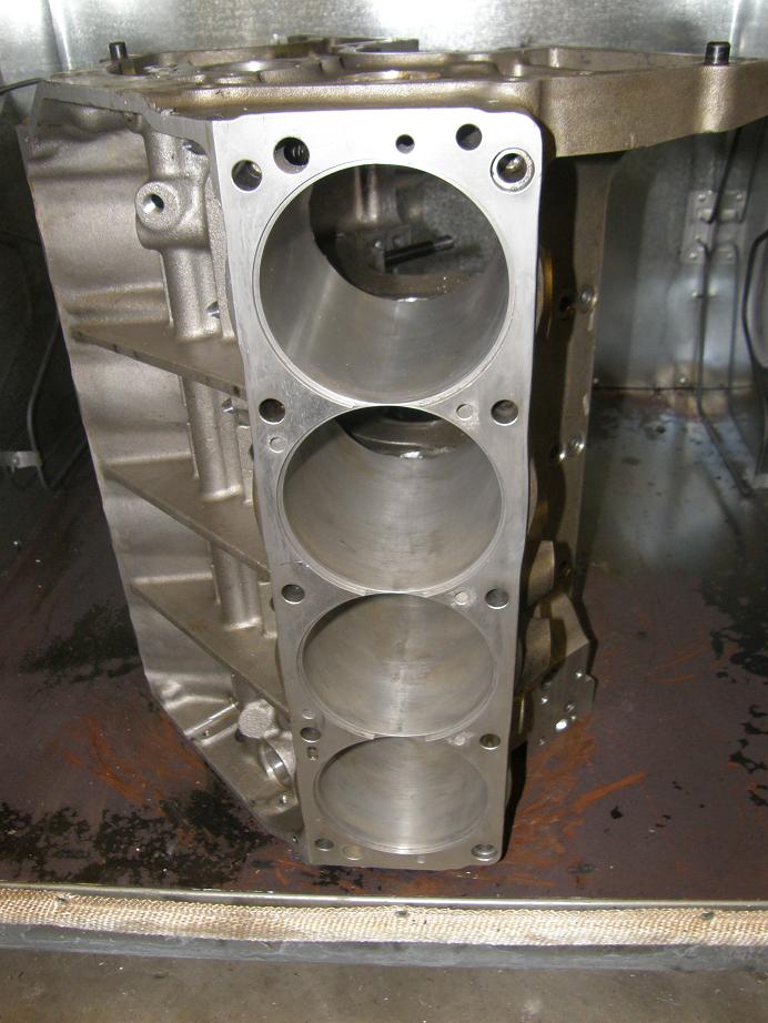
Here's a photo of the block in the oven showing cylinders 5-8, prior to installation of the sleeves:


I let the block warm up for an hour before I started the installation.  While I waited I cleaned all the oil off the sleeves, installed the O-rings, and lubricated each O-ring with a special lubricant designed to make installation easier.  Finally I cracked open the oven and installed sleeve #8.  It went in easily up to the O-ring, and then I had to use a deadblow hammer and a block of wood to push the sleeve into position.  I tried to keep the flat in the right spot, but sure enough by the time the sleeve was nearly installed it had rotated somewhat.  I tried twisting the sleeve to get the flat aligned correctly, but it wouldn't budge.  After trying to tap the sleeve with a hammer to get it into the proper position, I decided to shut the oven door and let the block heat back up, and try to come up with a solution.

Eventually I decided that I could use a small vise grip to grab the flange of the sleeve, and then hit the vice grip with a hammer to rotate the sleeve in the bore.  After ten minutes I opened the oven again, and after a couple of tries the vise grip and hammer approach worked, and I got the sleeve rotated into the correct spot.  A couple more strokes with the dead blow and the sleeve was all the way in.

I continued with this technique to get the remaining sleeves put into position.  In nearly all cases I had to grab the flange of the sleeve with the vise grip and rotate it so the flats would fit; the sleeves always wanted to turn a little while they were being driven in.  But finally I got them all into the correct position.  Here's a photo of cylinders 1-4, with sleeve #1 still not quite all the way into position:


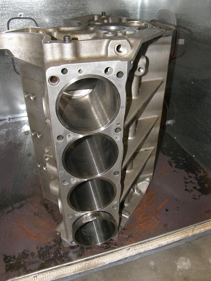
Now that the sleeves are installed, I will leak check the block this week.  If I find any problems I will have to either replace the O-ring on that particular cylinder or come up with some other solution.  Assuming the block is leak free, I will be ready to order pistons.  When that happens, I'll be sending some of the existing pistons to CP, and maybe they will be able to shed some light on my piston to valve clearance issues.
« Last Edit: February 20, 2012, 11:41:31 AM by jayb »
Jay Brown
- 1969 Mach 1, Drag Week 2005 Winner NA/BB, 511" FE (10.60s @ 129); Drag Week 2007 Runner-Up PA/BB, 490" Supercharged FE (9.35 @ 151)
- 1964 Ford Galaxie, Drag Week 2009 Winner Modified NA (9.50s @ 143), 585" SOHC
- 1969 Shelby Clone, Drag Week 2015 Winner Modified NA (Average 8.98 @ 149), 585" SOHC