Author Topic: 585" SOHC - Teardown, repair, rebuild, and re-dyno  (Read 31859 times)

0 Members and 1 Guest are viewing this topic.

jayb

  • Administrator
  • Hero Member
  • *****
  • Posts: 7406
    • View Profile
    • FE Power
585" SOHC - Teardown, repair, rebuild, and re-dyno
« on: November 27, 2011, 03:30:48 PM »
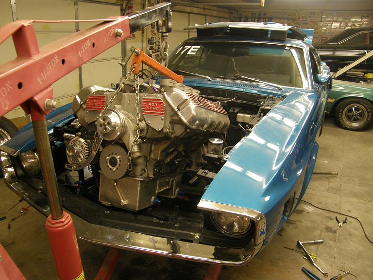
It's been a pretty busy last week and a half or so.  Last weekend I finally got around to pulling the wounded cammer motor out of my Drag Week car:


Teardown started last Sunday morning, and revealed some very unexpected and disturbing surprises.  Everything looked good as I pulled the valve covers, oil pan, and front cover.  The oil pan had a bunch of black crap in the bottom, and after looking at it for a while I concluded that it was probably some of that Moroso ceramic seal that found its way into the oil pan because of the coolant leak into the engine interior.  On Drag Week, after the oil pressure started going down and the coolant temperature started going up, Joel and I had stopped the car at an exit and found the water in the oil, and decided to throw in the towel.  We changed the oil and topped off the coolant in hopes of getting back to Topeka and our hotel under our own power, but after 20 miles on the way back, the oil pressure had dropped from 60 to 20, and I decided I'd better stop the car and get it towed.  Coolant temperature at this point was still running 160 as normal, so I made the assumption that I was losing the bearings in the engine.  The ceramic sealer remnants I found in the oil pan seemed to support this theory.  

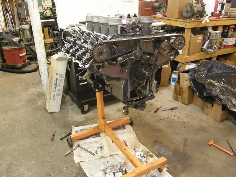
Next I pulled the rocker shaft and rockers off the engine.  Everything looked perfect here; just as I'd put it together.  Lash was good, roller wheels on the rockers all felt good, cam lobes looked perfect, etc.  Here's a photo of the engine at this point in the disassembly process:


Next I disassembled the front end, again with no issues.  The bearing in the Pond front cover looked fine, the bearings on the chain tensioner and fuel pump gear stand were fine, the Munro chain and all the gears looked fine.  I had checked the chain tension and the cam timing when I first pulled the front cover and that was all fine also.  So far, there was no indication of any reason for the engine to be down so much on horsepower.  I also pulled the cams, and was surprised to see that the bearings looked pretty good.  There was no indication of scoring or excessive wear, and the cam bearing journals looked fine.  If I was circulating some abrasive material through the oil and losing the bearings, I would have expected to see some wear at the cam bearings.  Hmmmmm...

Everything changed when I pulled the heads.  I pulled the right head off first, set it on the bench, and looked at the combustion chambers.  Everything looked normal.  Then I pulled the left head and did the same inspection.  Here's a photo:


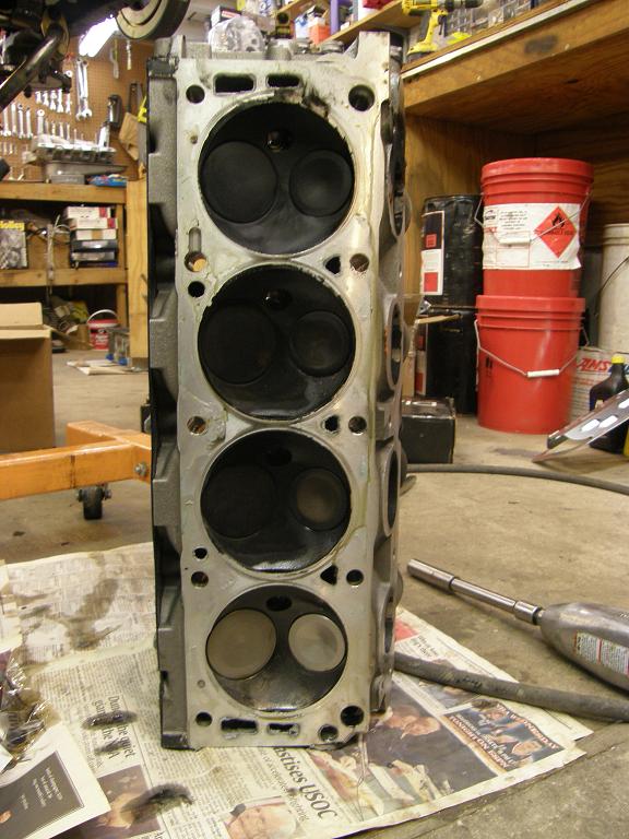
Look at how clean the #8 chamber is.  It almost looks like it wasn't even firing!  I couldn't believe that I would have missed that during the dyno pulls, but just to be sure I went back and checked the data, and sure enough #8 had normal exhaust temperature during the dyno pulls.  Maybe water was getting into that cylinder?  One important observation here was that this cylinder didn't look like this when I pulled the heads when the engine was on the dyno last summer.  Maybe when I put in the new head gaskets I didn't get a perfect seal on that cylinder...

Next I went back and looked at the right bank pistons, and was shocked by what I saw. Three out of the four pistons showed evidence of piston to valve contact!  The contact was all on the eyebrow portion of the intake valve relief, not down on the piston dome itself.  Further, the contact was really, really excessive, with aluminum from the piston peeling out away from the contact area.  This was a total surprise.  When I had pulled the heads with the engine on the dyno last summer, there was absolutely no evidence of piston to valve contact on this engine.  The heads had been planed .005", so this must have been the change that caused the contact, but .005"??  It looked like I had boatloads of contact, and that didn't come from a mere .005" cut on the heads.

Looking on the left bank, I saw some minor contact between the intake valve and the piston eyebrow on pistons 5 and 8, but nowhere near as extensive as on the three pistons on the other side.  Piston number 4 was definitely the worst of the bunch.  I decided that I'd better center punch all the valve locations on the pistons, so I disassembled the heads and removed the valves, then took a junk valve, cut the head off, and sharpened a point on it on my lathe.  I put a degree wheel on the crank and found TDC on number 1, then reinstalled the heads on each side and working around the engine rotation, center punched each piston with the pointed valve stem when it was at TDC.  Then I pulled the heads and measured the distance from the center point to the contact point on the pistons.  The dimension was 1.230".  Well, this didn't make sense; the valves in this engine are 2.300", so the valve shouldn't extend any further out from the center point that 1.150".  Yet I had contact at 1.230".  Hmmmm....

I rocked the pistons in the bores back and forth at TDC, and found that the top of the piston would move about .050" laterally, rotating on the piston pin.  This could explain part of the dimensional discrepancy, but not all of it.

I left the short block together, still puzzled by all this, and early this past week I gave my pal Blair Patrick a call.  Blair suggested that maybe the closest point of approach of the edge of the valve to the piston eyebrow wasn't at TDC, and thought I should center punch one of the pistons at a few degrees before and after TDC to see if the valve centerline moved further inboard at some point.  After hanging up with him I drew a few sketches of the piston and valve relationship, and with the cammer valve and piston geometry I couldn't see any way that the valve centerline would move inboard from TDC.  But it was worth a check, so I re-installed the right head and center punched #4 at -30, -20, -10, +10, and +20.  Furthest inboard position of the valve centerline was definitely at TDC.  Here's a shot of the piston with all the marks on it; the line scribed in the top of the piston points toward the center punch mark at TDC:


Tuesday night I pulled the short block the rest of the way apart.  Surprisingly, everything looked good.  In particular, the bearings looked perfect!  Another mystery; with new oil in the engine on my last 20 miles of the Drag Week drive, oil pressure was dropping.  Why?  The bearings and crank looked beautiful.

I checked the cylinder bores and they were out of round by .001" or .002" in some cases, but the measurement was done without a torque plate, so they might have still come back into line when the head studs were torqued.  I had been hoping to find an obvious answer for the loss of 150 HP on the dyno with this engine, but it was not apparent on the short block teardown.  (I don't think that the piston to valve clearance issue is related to the horsepower loss, because the loss was the same before and after the headwork and new head gaskets last summer).

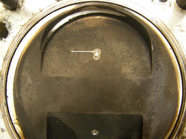
Wednesday I stopped up at R&R Performance and asked my pal Bryan up there what he thought of the piston to valve contact issue.  I brought along the #4 piston, and also the #4 intake valve.  With as hard as the valve was hitting the piston, I figured that this valve had to be bent, but it didn't really look like it, and I wanted Bryan to check it.  Sure enough, the valve was not bent.  Go figure.  Bryan measured the valve then set up a scribe compass, and put it in the center punch hole in the piston, then scribed a line around the piston dome to see where the valve should be.  It sure looked far away from the contact point.  Here's a photo of the top of the #4 piston:


The scribed line shows that not only is the piston contact point further outboard than the valve head is, but it is also offset to one side.  The pistons look like they are made correctly, judging by the center point on each one.  Just for grins I checked to cracks in the heads that may allow the guide to move around somewhat, but found nothing.  Guides were nice and tight, too.  Hmmmm...

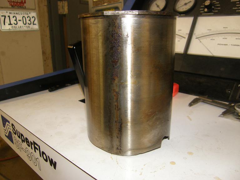
With this mystery lingering, this weekend I decided to pull the sleeves out of the block.  When I had originally offset bored this block we had broken through into the water jacket in cylinders 3, 4, and 8.  After installing the sleeves I had used a chemical sealant called Seal-All, available from Goodson, to seal up these leaks.  It held from 2008 through 2010, but apparently failed in the past year.  As a result I expected to see a lot of rust on the sleeves in cylinders 3, 4, and 8.  This would make them more difficult to remove.  To remove the sleeves you have to heat the block up to 300 degrees and then tap the sleeves out with a brass drift from the crankshaft side of the block.  As expected, cylinders 3, 4, and 8 were difficult to remove, and all three showed evidence of leakage.  Here's a shot of the block with the sleeves removed on the left bank, showing the clean aluminum casting in hole #7, and the rusty residue left inside hole #8:


However, I was surprised to see that on the right bank, there was rusty residue left inside holes #1 and #2, in addition to #3 and #4.  A look at the outside of sleeve #1 showed at least a partial explanation:


It looks like I have another head gasket leak here, and water is being forced down between the sleeve and the block, and out the bottom of the sleeve.  You can see evidence of the same leak in cylinder bore #1:


The leak in number 2 is a mystery at this point.  I think I will put a torque plate on this side of the engine, with a head gasket, and pressurize it to look for any leaks in the block casting in the #2 bore.

Short story - the engine was leaking water like a sieve, both in the expected places, and also in some unexpected areas involving the head gasket.  Was this the reason for the lack of power production?  I don't know, but it sure didn't help matters.  I'm looking at a few different options to more positively seal this block up, including either welding the block or O-ringing the bottom of the sleeves.  Neither option is perfect, but I think I can get 'er done.  Then it will be time for new sleeves, new pistons, and re-assembly of the engine.  Hopefully by then I will have figured out the deal with the piston to valve contact, and can get a new set of pistons built that will eliminate this problem.  I will post more under this topic as I get further along down the road to rebuilding this engine...


« Last Edit: November 27, 2011, 07:12:55 PM by jayb »
Jay Brown
- 1969 Mach 1, Drag Week 2005 Winner NA/BB, 511" FE (10.60s @ 129); Drag Week 2007 Runner-Up PA/BB, 490" Supercharged FE (9.35 @ 151)
- 1964 Ford Galaxie, Drag Week 2009 Winner Modified NA (9.50s @ 143), 585" SOHC
- 1969 Shelby Clone, Drag Week 2015 Winner Modified NA (Average 8.98 @ 149), 585" SOHC


Hemi Joel

  • Sr. Member
  • ****
  • Posts: 497
    • View Profile
Re: 585" SOHC - Teardown, repair, rebuild, and re-dyno
« Reply #1 on: November 27, 2011, 07:26:18 PM »
That is quite a mystery.  Heres an idea to chew on. If I remember my FE cylinder numbering correctly, it looks like the piston to valve contact on #4 is focused on the rear half of the piston.  The heavy side, considering your fore and aft piston to rod offset. Could the piston be rocking in the bore that much due to the offset?    
« Last Edit: November 27, 2011, 07:28:41 PM by Hemi Joel »

Kirk Morgan

  • Jr. Member
  • **
  • Posts: 43
    • View Profile
Re: 585" SOHC - Teardown, repair, rebuild, and re-dyno
« Reply #2 on: November 27, 2011, 07:28:36 PM »
Does your valve timing advance or retard a few degrees when the engine is at max RPM? That just blows my mind why that may happen. When you checked your valve guides did you look to see if there is a wear pattern? It will be very interesting to find the solution.  

Kirk

country63sedan

  • Jr. Member
  • **
  • Posts: 96
    • View Profile
Re: 585" SOHC - Teardown, repair, rebuild, and re-dyno
« Reply #3 on: November 27, 2011, 07:58:27 PM »
What do the piston skirts look like? If the valve to guide fit is tight, and the valves are straight, then the cause probably came from below. A piston rocking in the bore would explain the strange clearance difference. How's the fit on the rod bushings? (Nevermind, that should be the same as checking  clearance through rotation.) Your failures/issues are always head scratchers Jay! Good luck. Later, Travis.

WConley

  • Hero Member
  • *****
  • Posts: 1160
  • No longer walking funny!
    • View Profile
Re: 585" SOHC - Teardown, repair, rebuild, and re-dyno
« Reply #4 on: November 27, 2011, 08:42:52 PM »
Wow this is indeed a mystery!  It makes you wonder if those sleeves were moving around at all.

Any sign of fretting or polishing on the bottom lands that support the sleeves in the block?
A careful study of failure will yield the ingredients for success.

66FAIRLANE

  • Hero Member
  • *****
  • Posts: 558
  • Andy
    • View Profile
Re: 585" SOHC - Teardown, repair, rebuild, and re-dyno
« Reply #5 on: November 27, 2011, 10:27:14 PM »
Wow this is indeed a mystery!  It makes you wonder if those sleeves were moving around at all.

Any sign of fretting or polishing on the bottom lands that support the sleeves in the block?

Yes, thats what I was thinking too.

jayb

  • Administrator
  • Hero Member
  • *****
  • Posts: 7406
    • View Profile
    • FE Power
Re: 585" SOHC - Teardown, repair, rebuild, and re-dyno
« Reply #6 on: November 27, 2011, 10:33:55 PM »
Thanks for the comments; I took another look at some of this stuff tonight as a result.  

As far as rocking in the bore, the piston will rock back and forth at TDC about .050", along the piston pin axis as I mentioned in the original post.  After I discovered this I checked the piston to wall clearance at the skirt and it was right on at .006".  Piston skirts look good; the coating is still on the skirts.

Rocking in the other direction doesn't appear possible after looking at the piston and rod assemblies.  The pin fit is pretty much perfect.

I took another look at the valve guides, and they weren't quite as good as I had initially thought.  I put the #4 intake valve back in its guide, hung it about 1" open, and then fitted a dial indicator so that I could measure the side to side movement of the valve head.  At that lift I got about .010" side to side movement from one extreme to another.  This seems like its way too much, and may be a contributing factor.  Looking inside the guides, there was no obvious wear pattern, except that the wear seemed to be concentrated towards the bottom half of the guide.

A few years back I did some very extensive testing on the chain stretch on the SOHC, and how it affected timing, using magnets on the two cams and the crank, and magnetic sensors fitted to the timing covers.  What I found was that the right cam retarded a couple degrees between 3000 and 7000 RPM, and the left cam advanced a couple of degrees.  Since the right bank showed the primary contact with the intake valves, this doesn't really correspond with the cam retarding.  If the right cam had been advancing, I could see this as a contributing factor.  Of course, when I did this testing it was using a different chain and gears set, different cams, different springs, etc.  Who's to say what's actually happening with this particular engine.

The sleeves in the block don't actually sit down on a ledge at the bottom of the bore; the stop for the sleeves is the flange at the top of the bore.  I looked under a few of the sleeve flanges to see if there was any indications of movement, but didn't really see anything that would indicate that.  It's hard for me to believe that the sleeves would actually be moving around in the block more than a thousandth or two.  The deck surface of the block is fairly thick and is solid, so I don't think the sleeves could actually be moving around at the top.  At the bottom the sleeves tie into the metal making up the main webbing, so it seems unlikely this could move either.  The sleeves are held in place from the top by the sandwich of the flange against the block, the O-rings in the sleeves, the head gasket, and the head.  

Despite discovering the issue with the valve guides, the explanation for the valves hitting the pistons is still unclear...
Jay Brown
- 1969 Mach 1, Drag Week 2005 Winner NA/BB, 511" FE (10.60s @ 129); Drag Week 2007 Runner-Up PA/BB, 490" Supercharged FE (9.35 @ 151)
- 1964 Ford Galaxie, Drag Week 2009 Winner Modified NA (9.50s @ 143), 585" SOHC
- 1969 Shelby Clone, Drag Week 2015 Winner Modified NA (Average 8.98 @ 149), 585" SOHC


66FAIRLANE

  • Hero Member
  • *****
  • Posts: 558
  • Andy
    • View Profile
Re: 585" SOHC - Teardown, repair, rebuild, and re-dyno
« Reply #7 on: November 28, 2011, 12:27:43 AM »
I know it's probably 4/5ths of phuk all. But if you are looking for another couple of thou, I wonder how much the diameter of the valve head grows when its hot? And maybe length?

GJCAT427

  • Hero Member
  • *****
  • Posts: 662
    • View Profile
Re: 585" SOHC - Teardown, repair, rebuild, and re-dyno
« Reply #8 on: November 28, 2011, 06:54:22 AM »
Jay, what make is the block? From the looks of the liners I think you may have a poraisty(sp) problem? Are the bores siamised?  I know that I had a John Deere diesel that filled with water and couldn`t figure ouy why untill the liners were pulled and found the bottoms were ate from electrolis and ruined the oring seals at the bottom. I`m surprised the liners don`t have a bottom seal. This would elimanite a water leak if the block is poris. Just some thoughts. Garry (GJCAT427)

jayb

  • Administrator
  • Hero Member
  • *****
  • Posts: 7406
    • View Profile
    • FE Power
Re: 585" SOHC - Teardown, repair, rebuild, and re-dyno
« Reply #9 on: November 28, 2011, 09:37:11 AM »
It's a Shelby block.  I don't think it's a porosity issue; I have three others, and none of them have leaks.  This block has the water jacket exposed on cylinders 3. 4. and 8 because of the offset boring operation I performed on the block.  If there are other leaks that I don't know about, it's also probably due to the offset boring operation.
Jay Brown
- 1969 Mach 1, Drag Week 2005 Winner NA/BB, 511" FE (10.60s @ 129); Drag Week 2007 Runner-Up PA/BB, 490" Supercharged FE (9.35 @ 151)
- 1964 Ford Galaxie, Drag Week 2009 Winner Modified NA (9.50s @ 143), 585" SOHC
- 1969 Shelby Clone, Drag Week 2015 Winner Modified NA (Average 8.98 @ 149), 585" SOHC


machoneman

  • Hero Member
  • *****
  • Posts: 3853
    • View Profile
Re: 585" SOHC - Teardown, repair, rebuild, and re-dyno
« Reply #10 on: November 28, 2011, 10:17:44 AM »
The .010 clearance on the guides is unusual  for what I'll venture is short running time. How many miles or hours of operation on the engine? Using a PC type seal sometimes results in virtually no guide/stem oiling.

As to the valve-to-piston clashing, I think your comments on some intensive cam timing testing hit the nail on the head. The advancing/retarding cam 'feature' of the SOHC as you know has been mentioned in historical Ford racing tomes long ago, even leading to Sneaky Pete's one-off SOHC gear drive. Back then they weren't running the high lift/high duration camshafts and high spring pressures as you're doing today. I wonder if all this, added up with the on-the-throttle/off-the-throttle nature of street driving that 585 for Drag Week, unlike dyno testing, has lead to what I'll term chain whip and resultant valve clash?

Just a thought but unless something else pops up like loss of spring pressure, causing valve float, although some Rimac spring checking would tell.......?

Btw, I'm not suggesting a gear drive is needed! I also found Harvey Crane's own write-up on the SOHC chain issue. The original link is mighty long, one I'm sure Jay has seen before, but for others here's the excerpt:  

Innovation Gained From Engineering

Pete believed in the Ford SOHC 427 so much that when company wags reduced the factory support to a strangulation point Pete forged ahead.  He knew that the OHC design and Hemi configuration was the ultimate for a nitro engine and he continued to perfect it.  In the early days of running the SOHC 427 Pete encountered an alarming tendency of the engine to hang open a valve, creating a backfire situation and instantly launched blower!  Because the Cammer drove those wonderful SOHC camshafts via a long chain drive arrangement, Pete suspected that the chains were creating a "tolerance stacking" effect, lengthening during operation and creating a serious retardation in timing that was resulting in blower explosions.  To prove his theories to himself Pete brought his car, trailer and of course the massive 427 SOHC engine to Harvey's Hallandale shop.  Harvey had recently installed a then state-of-the-art, Heenan-Froude  dynamometer with all the instrumentation, for cam and component engine testing.  Pete dropped his Cammer motor onto the mounts and set up degree wheels on each bank, and a strobe timing light, to measure the chain stretch and valve timing retardation.  He also duct taped an 8mm home movie camera to a stand, aiming it directly at the degree wheel on the bank he suspected.  With this very rudimentary set-up he fired up the big Cammer and ran a couple of   conservative power runs.  Harvey recalled Pete's first fire-up test of the nitro-fed Ford:  Our dyno cell was located on the North side of the Hallandale shop, with a concrete block wall separating it from the main cam grinding shop.  The first time Pete fired up that blown, nitro 427 Ford engine our guys in the shop thought the building had exploded!  They all ran for the fire exits, sure that the whole side of the building was destroyed!  A couple days later, after we had the movie film developed, Pete had his proof.  The chain was definitely stretching and retarding the cam timing, causing the blower explosions.

Pete went back to Atlanta and during the drive home, decided that a gear-drive system was the most accurate, most reliable means of making the Cammer engines work to their full potential.

Again, when railbirds first saw Pete's amazing solution to the chain stretch problem, they crowed that Pete had "finally lost it".  His fix eliminated the long, unreliable chain completely and replaced it with a series of intricately machined, spur-toothed gears, all designed to fit inside a front cover fabricated from lightweight sheet aluminum.

It looked like Godzilla's pocket watch, and Pete's gear-drive solution remains one of drag racing technology's most intriguing achievements.


« Last Edit: November 28, 2011, 11:41:34 AM by machoneman »
Bob Maag

Hemi Joel

  • Sr. Member
  • ****
  • Posts: 497
    • View Profile
Re: 585" SOHC - Teardown, repair, rebuild, and re-dyno
« Reply #11 on: November 28, 2011, 10:30:47 AM »
I'd like to see a picture of that gear drive. Does Any one have one?

machoneman

  • Hero Member
  • *****
  • Posts: 3853
    • View Profile
Re: 585" SOHC - Teardown, repair, rebuild, and re-dyno
« Reply #12 on: November 28, 2011, 10:41:06 AM »
Click down to mercuryjunky's H.A.M.B. post and you'll see the front of Robinson's cammer gear drive with the inspection cover off:   

http://www.jalopyjournal.com/forum/showthread.php?t=356918&page=10

« Last Edit: November 28, 2011, 10:45:01 AM by machoneman »
Bob Maag

jayb

  • Administrator
  • Hero Member
  • *****
  • Posts: 7406
    • View Profile
    • FE Power
Re: 585" SOHC - Teardown, repair, rebuild, and re-dyno
« Reply #13 on: November 28, 2011, 12:34:45 PM »
Problems with the SOHC chain drive system are rather exaggerated, in my opinion.  If the chain is tight, variations in valve timing will be a few degrees at most, at least up to 7000 RPM.  Maybe it would be a lot more at 10,000 RPM, but I've never run this engine past 7500.  And even if the chain were whipping and stretching a lot, that doesn't explain why the impact point of the valve on the piston is so far off the valve's normal location. 
Jay Brown
- 1969 Mach 1, Drag Week 2005 Winner NA/BB, 511" FE (10.60s @ 129); Drag Week 2007 Runner-Up PA/BB, 490" Supercharged FE (9.35 @ 151)
- 1964 Ford Galaxie, Drag Week 2009 Winner Modified NA (9.50s @ 143), 585" SOHC
- 1969 Shelby Clone, Drag Week 2015 Winner Modified NA (Average 8.98 @ 149), 585" SOHC


machoneman

  • Hero Member
  • *****
  • Posts: 3853
    • View Profile
Re: 585" SOHC - Teardown, repair, rebuild, and re-dyno
« Reply #14 on: November 28, 2011, 12:57:42 PM »
Yes, the impact point being so far off is a really odd issue. Wonder if you can do an on-engine check with the actual valves (not just stems and center points) and checking springs and some Prussian blue or some other dye/paint marker at various pre-post TDC checks? Hard to believe though that even with .010 stem clearance the valve heads could move as far the pics show to cause the piston marks to show up outside the pockets.

I should have mentioned with the gear drive issue too that the vast, vast majority of successful SOHC racers did not use this invention. They ran the OEM or OEM-type Ford chains, gears, tensioners, guide rails, etc. quite successfully and merely advanced or retarded one of the cam's timing events the requisite 6-7 degrees (or thereabouts) for parallel phasing at high rpm. Only Robinson had the one-off gear drive.  

So, still a major mystery!    

On edit: what was btw the recorded intake/exhaust valve to piston clearance on this engine? Have you had the chance to see if its changed?  


« Last Edit: November 28, 2011, 01:49:08 PM by machoneman »
Bob Maag