Once again I made a lot of progress on the car this weekend, but once again I also fell a little short of my goals for the week. I did make it out to the shop on a couple of weekday evenings this week, and made some progress on the work under the car. The first thing I did was bend up a subframe connector out of roll cage tubing for the driver's side. After a couple of hours bending, fitting, and notching, I had the tube shown in the photo below:

The small tube coming off perpendicular to the long one was welded on after the photo was taken and also connects into the front subframe, to give some leverage to the bar. I planned to attach the bars to the front subframe by first welding some 1/8" plate to the side of the front subframe rail, and then welding the tube onto the plate, to spread the load. At the back the bar would tie directly into the 2X3 crossmember of the back half kit.
The next free night I worked on the transmission mount. I was getting tired of working around the floor jack that was holding the back of the transmission and the GVOD up, so rather than work on the passenger side subframe I spent some time figuring out how to make the trans mount work. I wanted to use the factory support welded into the unit body of the car that was used with the stock transmission mount, and it seemed like the best way to do this was to build a new mount out of 1" square steel tubing. The back half of the mount was pretty easy, just a straight piece of tubing with a little angle up on one end, but the front half had to dip down to clear the trans brake solenoid, complicating the design. Eventually I got it pieced together, with the back and front tubes welded together with a plate that I slotted some holes in on my mill, to allow some flexibility in position of the transmission. A photo of the partially completed mount is shown below:

After some more welding and some grinding, the mount was ready to install. It seemed to fit fine, and allowed me to pull the floor jack out for better access.
Saturday morning I got back onto the project by bending up the passenger side subframe connector, and spent the rest of the day grinding, fitting, and welding until the subframe connectors were installed. I also notched the original factory support for the transmission mount to allow the header collectors to sneak through this area, improving the ground clearance situation. Here's a photo under the car, showing the front half of the subframe installation and the trans mount and notch in the trans mount support:
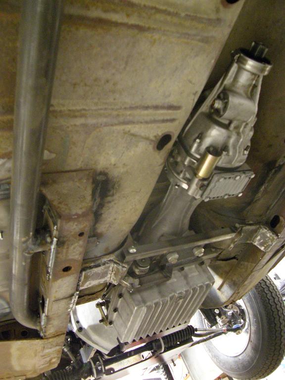
At the end of the day Saturday, after finishing all this stuff, I started thinking about what to do next. One of the bigger challenges left was to get the Wilwood brake pedal and master cylinders mounted, so I spent some time planning out how I would proceed on that in the morning. The Wilwood brake pedal mounts two separate master cylinders that extend into the engine compartment, but they are shorter than the stock master cylinder, so they wouldn't interfere with the big SOHC engine. The master cylinders mount to the firewall facing bracket of the pedal, but the pedal bracket itself is supposed to mount from the top, to some kind of a frame member.
When I had replaced the section of the firewall with a flat steel sheet, I had automatically been put under an NHRA rule which says that if you remove more than one square foot of the firewall, you have to run a crossbar between the front uprights for support. This crossbar can be 1.25" diameter .058" wall chrome moly, so I had ordered some of that tubing earlier from S&W race cars. I decided that I would use the crossbar as a forward support bracket to mount the pedal assembly. I figured I could run some square steel tubing between the crossbar and firewall, and mount the pedal assembly from that.
Sunday morning I was out to the shop by 9:00, hoping to make some good progress before noon, when I had some family commitments. I opened the door to the shop and the first thing I noticed was a whiff of propane in the air. Ruh-roh. I walked out of the shop without turning anything on, and went out and looked at the gauge on the propane tank. It was almost completely empty, showing only about 3% on the gauge. This explained the smell; when the level in the tank goes down that far the pressure in the lines drop, and one of my heaters has a hard time lighting. It will flip on and try to light for 20 seconds or so, then automatically shuts off to prevent a major leak of propane into the building. While it is trying to light, propane is coming out of the gas line, resulting in the smell. It will repeat this process every 15 minutes or so, and results in a faint propane odor in the shop.
I shut the valve off on the tank, carefully opened one of the overhead doors in the shop to air it out, and considered the necessity of working in the shop with no heat. I didn't want to just keep the other heaters on until the propane ran out, because the gas company needs to do a leak check on the building if the tank is completely empty. I decided that despite the lack of heat, I could tolerate working in it for a while, so I started back in on the car by 9:30. The thermometer in the shop read about 38 degrees, which wasn't too bad.
First thing I had to do was remove the factory brake pedal and pedal tree. Of course, this piece also functions to hold the steering column in position, so before removing the tree I had to fabricate an X-shaped wood support to hold the steering column in position. Later I planned to machine a U-shaped bracket to bolt to the crossbar, which would position the steering column. After the wood support was installed, I removed the factory brake pedal and pedal tree.
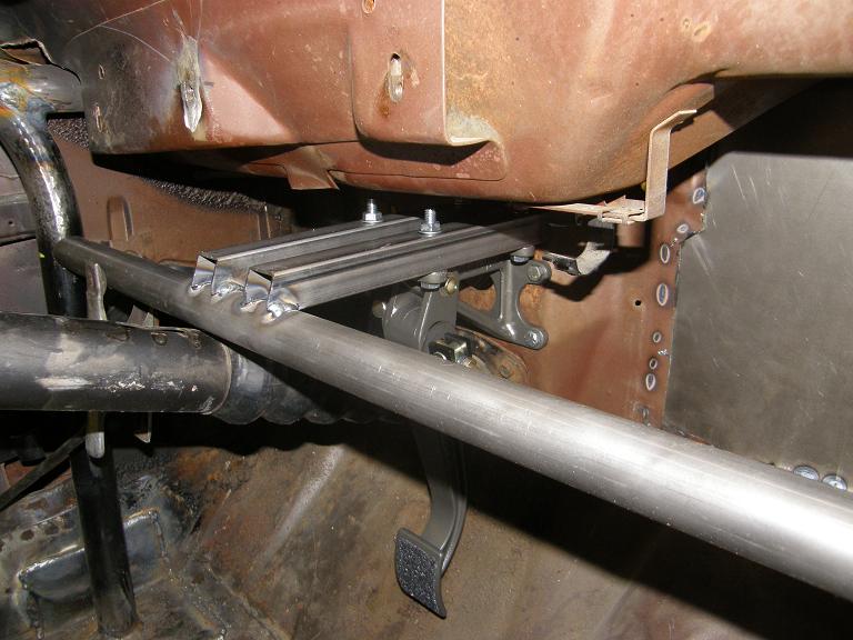
I cut the 1.25" diameter chrome moly crossbar carefully and notched the ends a little at a time, so that when it was finished I had a nice snug fit between the front cage uprights. Next I figured out where I wanted the pedal, and mounted it without the master cylinders, but using the master cylinder bolt holes so I could position it where I wanted against the firewall, and temporarily bolt it into position through the firewall. Then I made up a mounting frame that the top of the pedal assembly would go to, from 1" square steel tubing, that would weld to the crossmember and extend to the firewall, where it would bolt in place through a support plate I would weld to the outside of the firewall. By noon I had the basic arrangement frame up, as shown in the photo below:
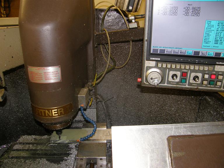
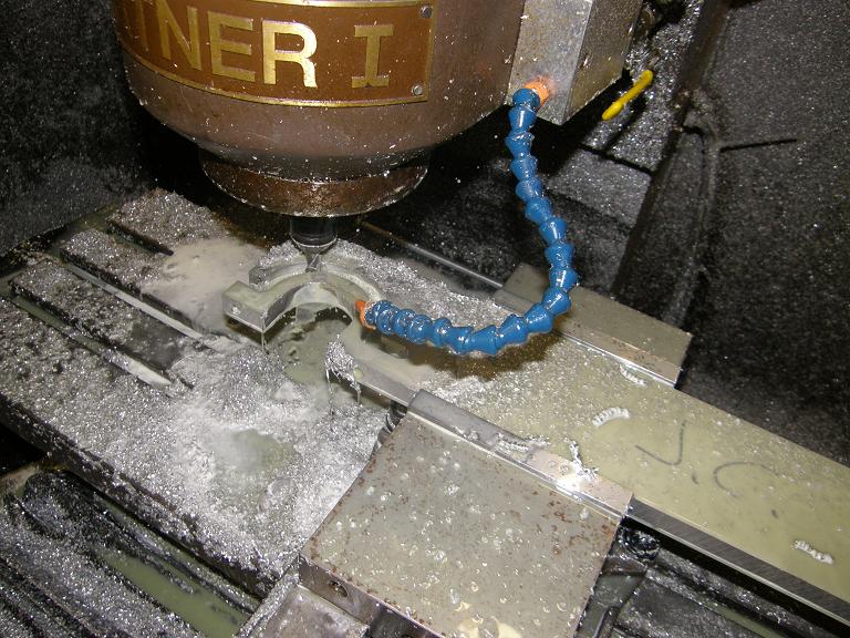
Later in the afternoon after returning from my family commitment, I decided that I'd better get to work on the U-shaped bracket that would hold the steering column to the crossbar. I decided to make this on my CNC machine, because it would be faster than doing it manually on the Bridgeport. I drew up a rudimentary sketch of what I wanted on my whiteboard, selected a piece of 3/4" thick aluminum plate that I had in my materials pile, and spent about a half hour programming the machine to make the part. Once it started up I was able to keep working on some other projects while the part was being made. Here's a couple of pictures of the CNC machine working on the part:
One of the things I did while the machine was running was to decide how I would bolt the U-bracket to the cross bar. I decided to take the low tech route on this, and cut a piece of 1 1/2" angle iron, with holes drilled in it at the proper locations to take the bolts from the U-bracket. The angle iron would just weld to the crossbar, and the bracket would bolt to that. Here's a photo of the finished aluminum U-bracket and the angle iron piece:
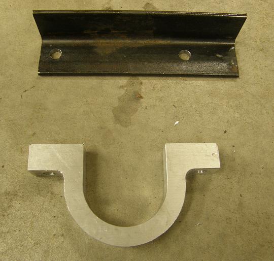
Before going in the house tonight to help the kids with their homework for Monday, I bolted the bracket to the piece of angle iron, and positioned it up against the crossbar. After double checking the steering column position to make sure it was correct, I tack welded the angle iron bracket to the crossbar. Finally, I removed the wood support on the steering column, and snapped the following photo:
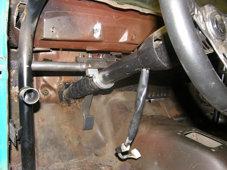
I still haven't welded in the crossbar yet, so now that everything is tacked in place I will remove the brake pedal assembly, disconnect the U-bracket, and pull the crossbar out of the car, where I can finish welding everything solidly in place, and add some support gussets and brackets to the brake pedal mount. Then, I can reinstall the crossbar and weld it in after it is positioned correctly.
I was hoping to get the Lokar gas pedal installed today, along with the supports for the seats so that I could bolt them into position, but I ran out of time for that. Besides, it was getting cold out there! I will have to call the propane company for a fill tomorrow. With luck I can get the gas pedal and seat supports done during the week this week, and my driveshaft will hopefully arrive from Mark Williams, so that I can finally tackle the rear end welding next weekend, in addition to finishing up the front crossbar and brake pedal / master cylinder installation. Then, the week after I can start the headers, and the chassis work will be getting close to completion. I will post another report next weekend.