I regularly find myself bemoaning the fact that I always seem to be behind schedule on my various projects. Many of my friends, and my wife, always point out that I am trying to do too much all at once. I have no doubt that this is true; perhaps it is a feature of my personality that I'm not happy without several balls in the air at once, so to speak.
Here is the latest "ball in the air". Knowing full well I would get my share of flack from machoneman (LOL!), I embarked on another project reminiscent of the old products from Pro-Stock Engineering. I had always admired their timing cover, with the removable plate allowing access to the top cam gear. I thought the basic idea was great, but that it needed a few more features to really take it to the limit. So, several months ago I started drawing up the FE Power timing cover. I did this in 2D CAD, and then the pattern maker that I have been working with on the intake adapters turned it into a 3D model. Here are a couple of screen shots of the machined model:
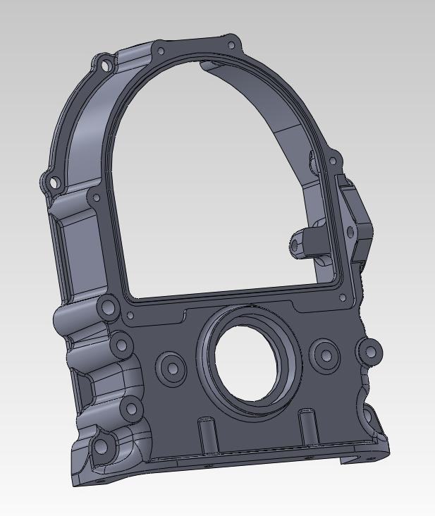
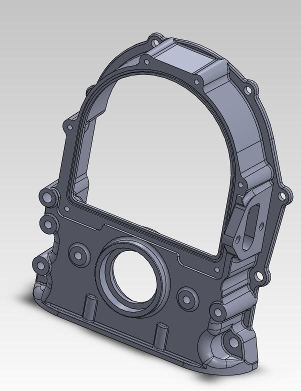
Let me point out some of the features of this timing cover. First, of course, there is the large opening allowing access to the top cam gear and the cam. The cover for this is going to be a laser cut steel plate. Notice the groove around the large opening; this is for an O-ring seal, so that no gasket will be required to seal the opening. I chose a steel plate for the cover to make sure it was rigid enough to compress the O-ring evenly between the attachment bolts, for a good seal. I will provide button head cap screws to bolt on the plate, and powder coat it for a nice appearance.
You will also notice five extra bosses on this cover, around the opening for the crankshaft. These will be drilled and tapped as blind holes, for use in attaching brackets to the timing cover. With my experiences in EFI I think it would be very helpful to be able to attach a bracket for a crank sensor directly to the top surface of the timing cover. In addition, with most electric water pumps available these days there is no provision for mounting brackets to hold the alternator or other accessories (my CVR water pump adapters being the exception). Especially for a low mount alternator, I thought that bosses like this would be very useful for use as a starting point for brackets if an electric water pump was used. Also, on the back side of the cover these bosses have some strengthening ribs; they may even be strong enough to use as a motor plate mount, although I'm really not sure about that at this point.
Also, there is a raised area around the crankshaft opening on the front of the cover. This is there so that a front seal can be installed in this position. Now, the back side of the cover also has the standard position for the front seal. The idea here is that you can use two seals, one reversed, and be able to seal the engine either with a vacuum pump/dry sump, or if the engine is running normally with some pressure in the crankcase. I've often run vacuum pumps on my engines, and usually I run with them disconnected on the street, so that you need the regular front seal. But when you connect them at the track, you need the reverse seal for optimum sealing. With the two seals, your engine is sealed up either way. One question about this approach, by the way, is will the front seal survive if the back seal is working effectively; in other words, if the front seal is not exposed to oil, will it eventually burn up? I was talking to Blair Patrick about this a while back when I was doing the design, and he suggested putting a little grease between the two seals, so I'm going to try that and see if both seals will live. If they don't, well I can just machine off the boss for the seal on the front of the cover. One other idea with this is to just use the seal in the normal location, and if the seal goes out, you can install one in the front more easily than replacing the one in the normal position.
I don't know how many people have had problems stripping the corner oil pan attachment bolts out of the factory front covers, but I certainly have, so I made this area of my cover thicker to allow more thread distance. Also the bottom front bolts are extended out with a boss, so that the head of the bottom bolt doesn't interfere with a longer oil pan bolt in the corner.
On the laser cut steel cover there will be two small threaded holes for attaching a factory timing pointer. One downside to this arrangement is that you will have to remember to put some sealer on the threads of those bolts, in order to prevent an oil leak there. And one other thing about that steel cover is that it can easily be drilled for a 1/2" barrel cam sensor, and a simple target like a bolt put into the top cam gear to make the cam sensor functional. Again this is an easy way to run a cam sensor in a full sequential EFI application, without having to buy a special distributor.
Several weeks ago I pulled the trigger on the casting patterns for this design. They were done in mid-May, and today I picked up the first prototype castings. Here's a few pictures:
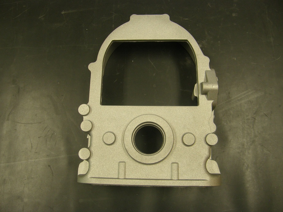
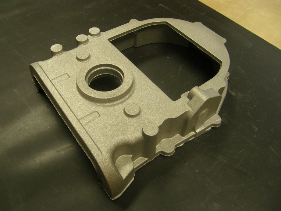
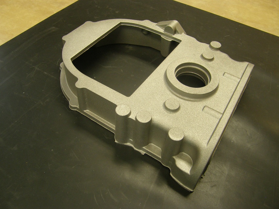
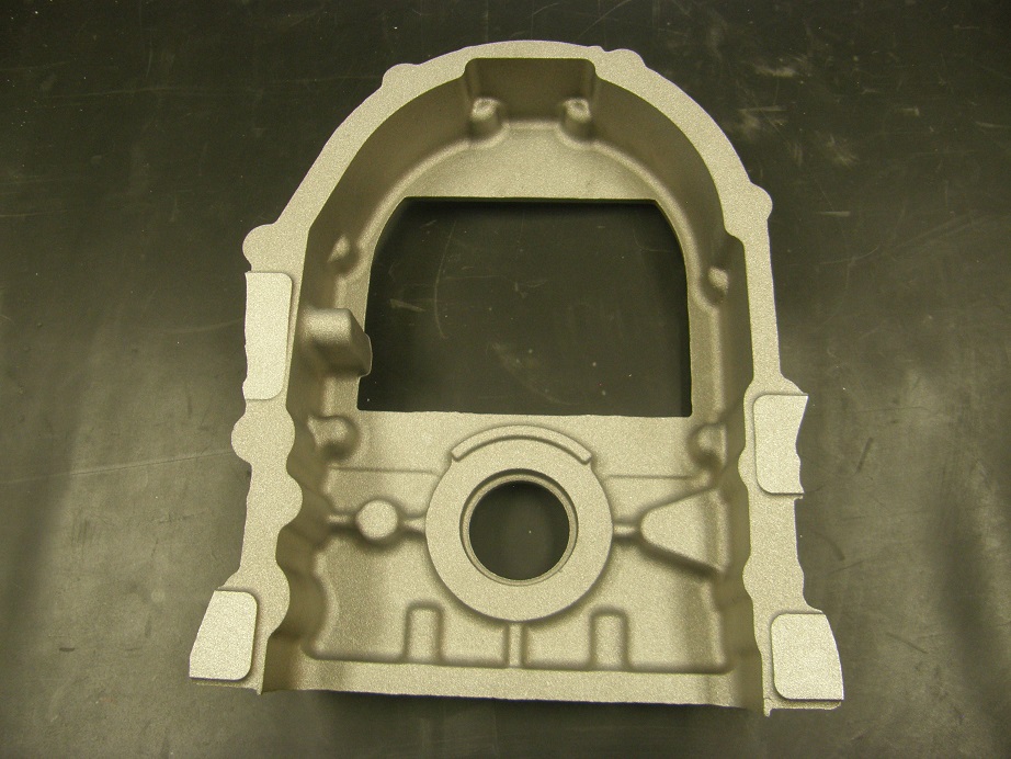
The squared-off part at the top of the opening is there for initial fixturing purposes only, and will be machined off as shown in the CAD model during the machining operations. I was ready to get started with the machining programs a couple of weeks ago but I am still behind on getting some of the intake adapter machining programs finished (such as the one for CHI ports in my standard intake adapter, and the standard version of the high riser adapter), so I was a little conflicted about starting this project. As it turned out, though, the pattern maker has some free time on his CNC machines, and he was able to quote me a very competitive price for machining these things. So, on the castings themselves I won't have to machine them myself at all, at least at first; the pattern guys are going to make all the fixtures so that they will work on my machine or on theirs, and are willing to machine the first 100 castings. That frees me up to keep going on the intake adapters. I will have to do some very minor machine work on the steel cover plates, and also powder coat them, but this won't require a significant time investment.
For this particular product I'm going to use the same rationale that I used for the FE intake adapters, which is to try to sell 100 covers and amortize my tooling costs over those covers. I think I should be able to sell 100 of them, but we will see. They'll be priced at around $225 complete. After I get the first prototypes machined, hopefully within the next month or so, I will test one out on one of my dyno mules, and if everything looks good, I'll post an ad in the vendor classifieds and start a list of people who want one.
So, what do you guys think? Will this be a worthwhile product?


