Author Topic: The Road to Drag Week 2014 - May 18  (Read 19341 times)

0 Members and 1 Guest are viewing this topic.

jayb

  • Administrator
  • Hero Member
  • *****
  • Posts: 7406
    • View Profile
    • FE Power
The Road to Drag Week 2014 - May 18
« on: May 18, 2014, 09:52:09 PM »
Once again this weekend things went more or less according to plan.  I made quite a bit of progress getting the engine assembled, and now the tough parts of the assembly are more or less complete.  I still have some fabrication to do to mount the crank sensor and make an arbor to drive the dry sump pump, but I think I'm on track to get this engine finished up by the end of the month.

The first task on Saturday was to get the timing chain setup put together.  I started by installing the cams in the heads, with only the first cam cap in place to retain them.  Here's a picture of the right cam installed, but without that first cap in place.  Note the numbers on the cam; there is a center dot, and then a 2 and a 4 on either side of the center dot.  That center dot should be point straight up with respect to the head surface, or 90 degrees from the head surface:


Here's a picture of the whole right cam installed:


After I had the cams in place I installed the cam gears.  The dot on the cam gear should line up with the dot in the previous photo on the cam, and be positioned so that the dot on the cam gear is about 45 degrees from vertical.  This is the correct position for the cam gears when you go to install the chain.  Here's a photo:


Notice the alignment pin stuck into the cam gear, with the 10-24 allen head screw coming out of it.  This pin goes through the gear and into a matching hole in the cam.  Advancing or retarding each cam can be done by moving this alignment pin.  Currently the pin is in the center position, so this cam is installed straight up.  If you move the pin one hole to the right, you are advancing the cam about 3 crankshaft degrees.  One hole to the left, and you are retarding the cam the same amount.  The 10-24 bolt is installed temporarily, to allow easy removal of the alignment pin (which is 10-24 threaded on the inside).  When you move the pin, of course, you have to move the cam relative to the gear, so that the next hole in the cam lines up.  This advances or retards the cam.  In the next picture, you can see a couple of flats ground into the cam; these are sized for a 7/8" wrench.  You can put a wrench on the cam and move it back and forth with the pin out, to get the holes in the cam and the gear lined up.  The next picture also shows the rocker shafts and two rockers installed, so that once I get the right cam degreed I can check piston to valve clearance (there are still checker springs on the valves for cylinder 1):


Next I added the timing chain guides and the oil squirters to the front of the engine.  The timing chain guides are pretty simple, you just have to bolt the bottom one in place, and then put the top one on after the chain has been installed.  Next the chain is installed, and here is where the dots on the timing gears become important.  First, the gear on the stub cam should have its timing mark pointed straight down, while as mentioned previously the two cam gears need to have their timing marks about 45 degrees off from vertical, towards the outboard side of the engine.  Then you can put the chain in place.  The top bolt on the timing chain tensioner must be removed, though, and the tensioner dropped as far down as possible, in order for the chain to fit.  The factory chains had three colored links that had to line up with marks on the timing gears.  Most of the aftermarket chains don't have those colored links, so I color them myself using some paint markers.  The way to do this is to lay the chain on a bench in front of you, and working clockwise around the chain, color one link for the stub cam gear, then count 63 links, then color the next link for the right cam gear, then count 69 links, then color the next link for the left cam gear.  You should then have 57 links between the colored link for the left cam gear and the link for the stub cam gear.  There are a total of 192 links in the chain.  After you have the links colored, drape the chain in place, making sure that the colored links go on the tooth with the dot on each of the cam gears and the stub cam gear.  Then lift up the tensioner and install the top bolt, and you are more or less finished.  The last thing you have to do is install the top timing chain guide.  One thing about the aftermarket top timing chain guides is that the rivets that they use to attached the nylon rubbing blocks to the guide stick up a long way past the top of the sheet metal chain guide, and unless you grind them down pretty far, the timing cover won't fit over them.  So you have to make sure that you grind the rivets if you've got an aftermarket guide.  When you're done the front are of the motor will look like this:


After putting the chain on I also install some oil squirters, tapping off the main oil galley in each head, to oil the bearings in the tensioner arm and the fuel pump gear.  These bearings don't get a normal source of oil, and for race only use probably don't need this modification.  But if you are idling in traffic for extended periods of time, then IMO its a good idea to add them.  Some people think that these auxiliary oil sources are for the chain, but the chain really doesn't need additional oiling; it gets plenty of splash oiling even at low speeds.  But the bearings in the tensioner arm and the fuel pump gear don't necessarily get this oil supply, especially since as they are spinning, because they are throwing oil away from the center of the gear, not towards it.  So for extended idling I always like to make this modifications.  The photos below show these auxiliary oil squirters; I make them out of 3/16" brake line and squeeze the ends shut so that there is only a .020" or so orifice for the oil to come out.  This makes a nice little squirt of oil right at the bearings, without taking too much oil from the main oil galleries.


In that last photo you can see the bolt just to the left of the primary timing gear that goes into the block's water jacket.  You need sealer on the thread of this bolt, and all around it, to ensure there are no leaks here.

When it comes to tightening the chain, there are a lot of different theories about this out there.  Several years ago when Earl Wade was still alive I spent quite a bit of time on the phone talking to him about this topic.  Earl basically said that he liked to keep the chain pretty tight, and he suggested the following way to monitor it.  Earl said to paint some blue machinist's dye on the top of the tensioner arm.  If the chain gets too loose, it starts hitting that tensioner, and you can easily see the marks in the blue dye when that happens.  Here's a couple of pictures of the tensioner arm on this engine; in the first picture you can see some witness marks where the chain has been hitting the arm, and the second photo shows what it looks like after the top has been painted with the blue dye:


Before the chain can really be tightened, however, the front cover has to go on the engine.  The reason is that if you tighten the chain before that you can pull the nose of the stub cam off by several thousandths of an inch, and make it really tough to install the front cover.  In fact I have been told that some of the stock, cast stub cams have actually been broken this way.  So, before proceeding with any chain tightening its time to install the front cover.  Unfortunately I'm out of  time tonight, but I'll add to this thread in the next day or two with the latest progress on the engine.


Jay Brown
- 1969 Mach 1, Drag Week 2005 Winner NA/BB, 511" FE (10.60s @ 129); Drag Week 2007 Runner-Up PA/BB, 490" Supercharged FE (9.35 @ 151)
- 1964 Ford Galaxie, Drag Week 2009 Winner Modified NA (9.50s @ 143), 585" SOHC
- 1969 Shelby Clone, Drag Week 2015 Winner Modified NA (Average 8.98 @ 149), 585" SOHC


cjshaker

  • Hero Member
  • *****
  • Posts: 4460
    • View Profile
Re: The Road to Drag Week 2014 - May 18
« Reply #1 on: May 18, 2014, 10:45:26 PM »
Dang, that's a lot of gasket surface area to seal up!

I noticed how close that chain was to the tensioner in that first picture. The machinist dye is a good idea. Also seems like that top guide could be longer. That is a long stretch of chain for that short of a guide. The 4.6/5.4/5.0 engines use a slightly rounded guide that is designed primarily to combat the "whipping" action of the chain, and it's much shorter than that SOHC top section. I'd guess that that is where a lot of the cam "movement" comes from at speed. Have you ever noticed witness marks above that top section of chain?

edit: I see there are nylon rubbing blocks on the top surface of that upper guide, but they do little to "guide" the chain. Just primarily try to limit the jumping motion I suppose. It would be interesting to see that section of chain in super slo-mo at speed.
« Last Edit: May 18, 2014, 10:54:15 PM by cjshaker »
Doug Smith


'69 R-code Mach 1, 427 MR, 2x4, Jerico, 4.30 Locker
'70 F-350 390
'55 Ford Customline 2dr
'37 Ford Coupe

cobracammer

  • Hero Member
  • *****
  • Posts: 1165
    • View Profile
Re: The Road to Drag Week 2014 - May 18
« Reply #2 on: May 19, 2014, 11:29:42 AM »
Hey Jay!  Awesome post.  This will really help me out with the timing portion.  So, I think you have to advance one side and retard the other correct? (Something like 4 degrees?)  can go just quickly go over how many degrees the Passenger/Driver side gets?

Thanks again!
Jason
2005 Saleen S281 (427 SOHC 2 X 4 EFI swap), T56 Magnum XL 6 speed, 9" Currie rear with 3.89 Gears

Drew Pojedinec

  • Hero Member
  • *****
  • Posts: 2116
    • View Profile
Re: The Road to Drag Week 2014 - May 18
« Reply #3 on: May 19, 2014, 01:53:33 PM »
That is just too much chain :P

How does everything stay balanced and the harmonics not get crazy with all that?  I'm no expert on SOHC engines, but I work on and fix industrial engines that often run for well over 50,000 hours, I just don't see how that setup could be made to run 100,000 miles without major adjustment issues and problems.  You'd need to either design a gear to gear system or have the tensioners be more self tensioning for any sort of longevity.

Just cuz it's interesting, what Cat puts on the end of the camshafts in our C32 engines:


Either way, thanks Jay, this is super interesting.

Drew

cobracammer

  • Hero Member
  • *****
  • Posts: 1165
    • View Profile
Re: The Road to Drag Week 2014 - May 18
« Reply #4 on: May 19, 2014, 03:00:19 PM »
Dang, that's a lot of gasket surface area to seal up!

I noticed how close that chain was to the tensioner in that first picture. The machinist dye is a good idea. Also seems like that top guide could be longer. That is a long stretch of chain for that short of a guide. The 4.6/5.4/5.0 engines use a slightly rounded guide that is designed primarily to combat the "whipping" action of the chain, and it's much shorter than that SOHC top section. I'd guess that that is where a lot of the cam "movement" comes from at speed. Have you ever noticed witness marks above that top section of chain?

edit: I see there are nylon rubbing blocks on the top surface of that upper guide, but they do little to "guide" the chain. Just primarily try to limit the jumping motion I suppose. It would be interesting to see that section of chain in super slo-mo at speed.

Seeing that the Timing chain is set to be a "whisper" space from the chain guides, I would venture a guess that the chain hits the nylon blocks often?  I would think if the chain moves enough to mark the machinist dye on the tensioner arm, that the nylon guides are being hit quite frequently by the chain?
Jason
2005 Saleen S281 (427 SOHC 2 X 4 EFI swap), T56 Magnum XL 6 speed, 9" Currie rear with 3.89 Gears

jayb

  • Administrator
  • Hero Member
  • *****
  • Posts: 7406
    • View Profile
    • FE Power
Re: The Road to Drag Week 2014 - May 18
« Reply #5 on: May 19, 2014, 11:17:20 PM »
Finally got a chance tonight to sit down and finish with this week's installment.  After the chain and all the drive components were installed, on Saturday evening I put the front cover on.  For some reason, for me anyway, this is always a big pain.  The covers never really seem like they want to fit right, and it is always kind of a fight to get them on there.  The big issue seems to be getting the nose of the stub cam through the bearing that is pressed into the cover, and getting the top of the cover over the top chain guide.  I usually have to have a plastic hammer nearby to help tap the cover into place.

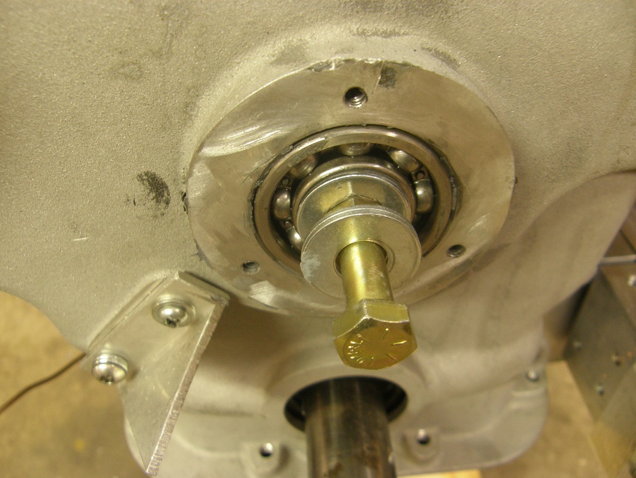
In one of the previous photos you can see the gaskets required between the backing plate and the front cover.  Those need to be glued in place on the backing plate with sealer, and then more sealer used on the front cover side before you try to install the front cover.  In front of the front cover the water pump bolts on, but I don't even try to install the water pump at this point; it will take you plenty of time to install the front cover alone.  Before putting the sealer on the front cover side of the gaskets I always like to test fit the front cover to see what I'm in for.  This time it looked like it would more or less go on OK, with some of the usual convincing.  I made sure that I had all the bolts I needed handy, then put the sealer on the front cover side of the gaskets and started the installation.  The nose of the stub cam is what really indexes the front cover, so you've got to make sure that you have that lined up before you can start pressing the cover into place.  As you try to push the front cover into position the stub cam will want to slide back into the block; I use a 3/8" bolt with some washers as kind of a puller, to pull the nose of the stub came through the bearing.  Picture below:


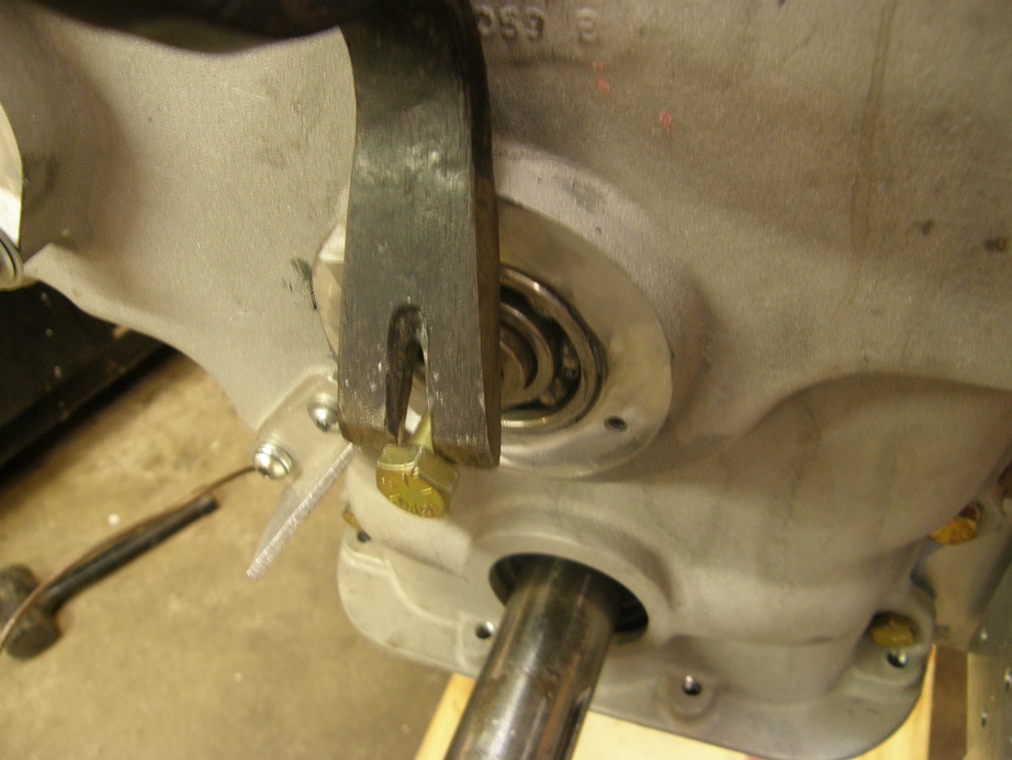
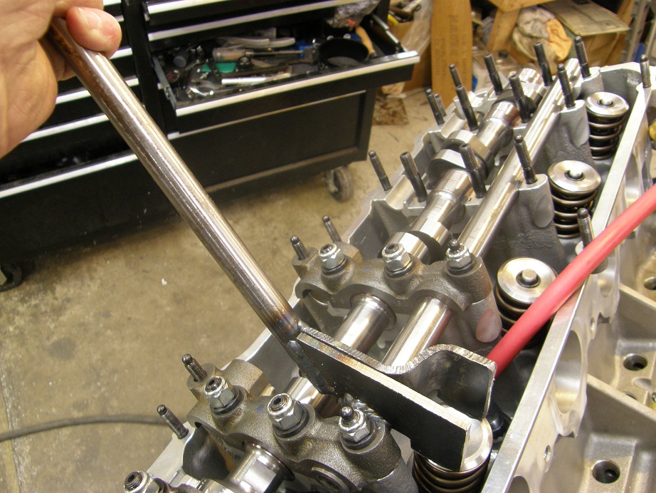
As you are tightening that bolt you need to be working the top of the cover into place over the top chain guide.  Once the stub cam is pulled flush with the front surface of the bearing, the little bolt puller arrangement won't work anymore.  Then its time to go to the pry bar, which by the way is right out of the Ford shop manual.  Here's a photo of me prying the stub cam forward some more:


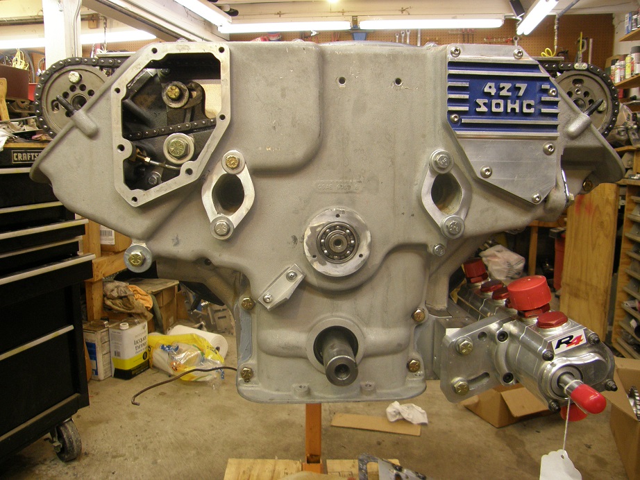
As you pry forward on the stub cam you need to be moving the front cover back into position, and you can start getting some of the bolts in place.  Finally when the stub cam is pulled far enough through the bearing you will expose the snap ring groove in the stub cam.  By this time you can tighten the four water pump bolts (even though the water pump is not installed yet; these are dummy bolts just to hold the front cover in place, and seal it to the backing plate), plus the remaining bolts in the front cover.  The last ones I do are the top four bolts that hold the backing plate to the front cover.  These are 1/4-20 bolts, and usually they are kind of difficult to get into place.  There is also a gasket that can be used between the top of the backing plate and the top of the cover, but I never use it; it always seems to be more trouble than it is worth.  I fill the gap between the front cover and the backing plate at the top with sealer, then draw them together with the four bolts, and wipe off the excess sealer.  It always seems to seal up fine that way.  Here's a picture of the front cover installed at this point:


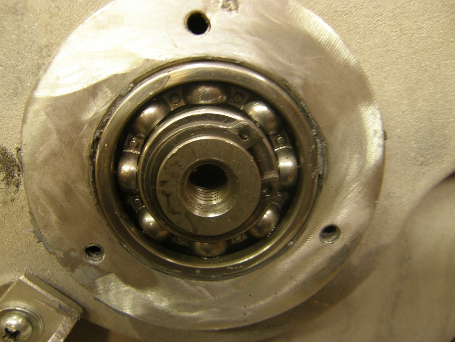
Once the cover is finally in place you can install the snap ring on the stub cam.  This is not some garden variety snap ring, it is a much thicker than usual snap ring, special for this application.  Make sure that the stub cam is pulled out enough to expose the whole groove, and then use a heavy duty snap ring pliers to install the snap ring.  Here is a photo of the end of the stub cam with the snap ring installed:


I called it a night at that point, feeling the need for an adult beverage  ;D  On Sunday I went back out to the shop to check my piston to valve clearances and degree the cams.  First I installed the crank sleeve and the harmonic balancer, which is a fully degreed ATI unit, making the use of a degree wheel unnecessary.  Then I tightened the chain up to where I thought it should be when the engine was warmed up and running.  It's kind of hard to describe this, but as you tighten the tensioner bolt and keep your finger on the chain through the inspection cover opening, you can feel the chain start to get tight.  At some point the chain will feel pretty tight and it will start to get a little bit harder to turn the tensioner bolt.  At this point you are starting to stretch the chain, which I prefer to avoid.  There was a recommendation to torque the tensioner bolt to 110 in-lb in a book I read a while back, but it didn't really specify whether the tensioner bolt was lubricated or not, or with what lubricant, so I'm not sure how reliable that figure is.  For what its worth, where I was comfortable tightening the tensioner bolt turned out to be about 60 in-lb.  110 in-lb was only about 3/8 turn more.

Also please note that this is being done with the engine cold for purposes of timing the cams; with an aluminum block and heads, you don't want to start the engine with the chain this tight, because when the block and heads expand the chain will stretch.  Normally I try to tension the chain with the engine hot after it has been running for a while and then shut off.  I think this gives you the correct tension.  The chain will be looser of course when the engine cools.  I would probably back the chain tensioner bolt off 3/8 of a turn or so before starting the engine for the first time, and then retension the chain when the engine warms up.

Finally it is worth pointing out that the valve springs acting on the cam can make the chain appear looser or tighter than it really is.  If you get used to opening up the inspection cover and pushing down on the chain to gauge its tension, you can get fooled by this because the valve springs might be twisting one cam one way and the other cam the other way, therefore making one half of the chain tighter and the other half looser.  To get a really good feel for the chain tightening, you need to pull the rocker shaft clips and move the 1,2,3,6,7,and 8 cylinder rockers over so that they are not acting on the valve springs, and then move the crankshaft so that the engine is between the #5 and #4 firing strokes.  This way the #4 and #5 rockers (which are not able to be slid out of the way on the rocker shafts) will be on the heels of the cams, and so no torque from the valvesprings can be imparted to the chain through the camshafts.  At this point you can get a true feel for the chain tension.

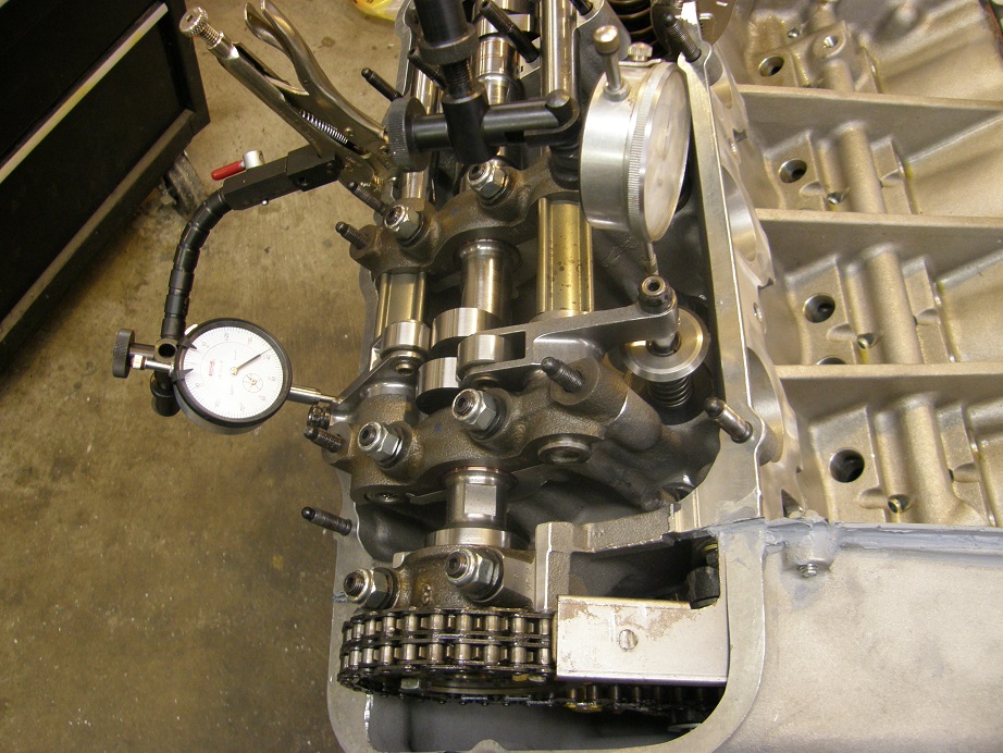
Of course I hadn't installed any of the rockers yet, except for the ones on the checker springs, so I didn't have to worry about any of that on Sunday.  I tensioned the chain to a point where I was satisfied with it, and then degreed the right camshaft using the intake centerline method that Comp Cams recommends.  I started off with the right cam straight up, and it came in at 116 for the ICL.  Then I checked and recorded piston to valve clearance, and moved to the next pin because I wanted to advance the cams as far as possible.  Here's a picture of my setup with two dial indicators, allowing me to check piston to valve clearance for both valves at the same time:


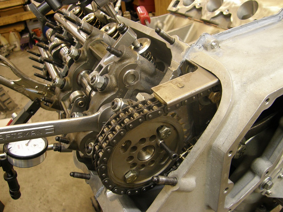
Continuing to move the alignment pin and check piston to valve clearance I got all the way down to 101 degrees in 3 degree increments.  After 101 degrees I ran out of PV clearance, but I don't think I'll have to go that far anyway.  But now I know what the limits are.  Here's a photo of moving the cam with the alignment pin pulled out so it is not engaging the holes in the cam, and the 7/8" wrench on the flats of the cam:


To start with I set the ICL back to 107 on the right cam.  I decided to leave it at that point and not do the left cam, but when I do it I'll check cylinder #6, because it will make for easier math since it is 360 crankshaft degrees apart from cylinder #1.  I usually set the left cam to be 3-4 degrees retarded as compared to the right cam; I did a bunch of experiments on this with my first SOHC dyno mule back in 2007, and found that at 7000 RPM the right cam retarded 2 degrees, and the left cam actually advanced about 1.5 degrees.  So, I keep them separated by this amount and figure at speed that my cam position is about in the middle.

Next I pulled the checker springs and installed the real valve springs on number 1.  I just used compressed air in the cylinder and a lever type spring compressor that I fabricated several years ago.  Here's a photo:


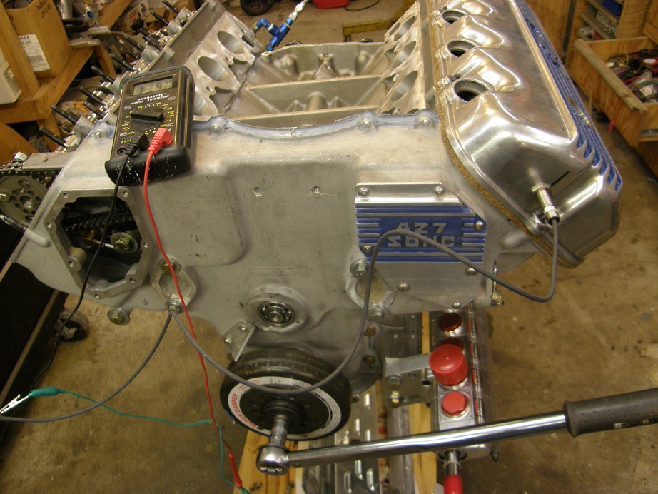
It was about the end of the day on Sunday, and I wanted one last job that wasn't too difficult, so I decided to figure out where and how to install the cam sensor.  This sensor needs to fire after cylinder #8 sparks, but before cylinder #1, so that when the ECU sees the cam sensor fire it knows that the next cylinder that fires will be #1.  This is necessary for a full sequential EFI setup.  I had been hoping to be able to put the sensor in the timing cover, but prior to installing the timing cover I figured out that this was not going to be possible, so instead I decided to put it in the valve cover.  I will be using a long bolt in one of the cam gear bolt positions as a target for this sensor, which is a magnetic sensor that will turn on whenever a ferrous target comes in close proximity.  It took me longer than I thought to get this set up properly, but finally I had the valve cover drilled, the sensor and target installed, and the electronics powered up so I could read the sensor when it turned on.  Here's a picture:


After some adjustments I got the cam sensor to trigger about 60 degrees before #1 fired, which will work just fine.

Next weekend I have a full 3 days on this project.  I should be easily able to get the rest of the engine together, save for whatever fabrication is required for the crank sensor and dry sump pump drive.  I'm looking forward to seeing the whole engine back together again.  I'll post another update next Monday.
Jay Brown
- 1969 Mach 1, Drag Week 2005 Winner NA/BB, 511" FE (10.60s @ 129); Drag Week 2007 Runner-Up PA/BB, 490" Supercharged FE (9.35 @ 151)
- 1964 Ford Galaxie, Drag Week 2009 Winner Modified NA (9.50s @ 143), 585" SOHC
- 1969 Shelby Clone, Drag Week 2015 Winner Modified NA (Average 8.98 @ 149), 585" SOHC


jmlay

  • Full Member
  • ***
  • Posts: 199
    • View Profile
Re: The Road to Drag Week 2014 - May 18
« Reply #6 on: May 20, 2014, 06:52:28 AM »
Have you considered using studs & nuts on the front cover -vs- bolts? It may be easier to get everything lined up, needing one less hand. But I have zero experience with a cammer.
Mike

jayb

  • Administrator
  • Hero Member
  • *****
  • Posts: 7406
    • View Profile
    • FE Power
Re: The Road to Drag Week 2014 - May 18
« Reply #7 on: May 20, 2014, 07:38:44 AM »
That is just too much chain :P

How does everything stay balanced and the harmonics not get crazy with all that?  I'm no expert on SOHC engines, but I work on and fix industrial engines that often run for well over 50,000 hours, I just don't see how that setup could be made to run 100,000 miles without major adjustment issues and problems.  You'd need to either design a gear to gear system or have the tensioners be more self tensioning for any sort of longevity.

Drew

I think the chain setup was designed to last 500 miles (Daytona 500), rather than 100,000, although a lot of people have put many miles on these things, including myself.  With the minimal chain guides and the fixed tensioner you have to stay on top of the chain tension, or the chain will stretch and get too loose.  I've had thoughts of designing a self tensioning system for one of these engines, using engine oil pressure to pressurize a hydraulic cylinder and apply force to the tensioner, but have never gotten around to it...
Jay Brown
- 1969 Mach 1, Drag Week 2005 Winner NA/BB, 511" FE (10.60s @ 129); Drag Week 2007 Runner-Up PA/BB, 490" Supercharged FE (9.35 @ 151)
- 1964 Ford Galaxie, Drag Week 2009 Winner Modified NA (9.50s @ 143), 585" SOHC
- 1969 Shelby Clone, Drag Week 2015 Winner Modified NA (Average 8.98 @ 149), 585" SOHC


jayb

  • Administrator
  • Hero Member
  • *****
  • Posts: 7406
    • View Profile
    • FE Power
Re: The Road to Drag Week 2014 - May 18
« Reply #8 on: May 20, 2014, 07:40:11 AM »
Seeing that the Timing chain is set to be a "whisper" space from the chain guides, I would venture a guess that the chain hits the nylon blocks often?  I would think if the chain moves enough to mark the machinist dye on the tensioner arm, that the nylon guides are being hit quite frequently by the chain?

I think the nylon guides are always in contact with the chain at some point.
Jay Brown
- 1969 Mach 1, Drag Week 2005 Winner NA/BB, 511" FE (10.60s @ 129); Drag Week 2007 Runner-Up PA/BB, 490" Supercharged FE (9.35 @ 151)
- 1964 Ford Galaxie, Drag Week 2009 Winner Modified NA (9.50s @ 143), 585" SOHC
- 1969 Shelby Clone, Drag Week 2015 Winner Modified NA (Average 8.98 @ 149), 585" SOHC


jayb

  • Administrator
  • Hero Member
  • *****
  • Posts: 7406
    • View Profile
    • FE Power
Re: The Road to Drag Week 2014 - May 18
« Reply #9 on: May 20, 2014, 07:43:16 AM »
Have you considered using studs & nuts on the front cover -vs- bolts? It may be easier to get everything lined up, needing one less hand. But I have zero experience with a cammer.

Actually lining everything up isn't the issue, because the nose of the stub cam and the top chain guide do that for you.  I can see the appeal of using studs though, especially on the water pump bolts.
Jay Brown
- 1969 Mach 1, Drag Week 2005 Winner NA/BB, 511" FE (10.60s @ 129); Drag Week 2007 Runner-Up PA/BB, 490" Supercharged FE (9.35 @ 151)
- 1964 Ford Galaxie, Drag Week 2009 Winner Modified NA (9.50s @ 143), 585" SOHC
- 1969 Shelby Clone, Drag Week 2015 Winner Modified NA (Average 8.98 @ 149), 585" SOHC


thatdarncat

  • Hero Member
  • *****
  • Posts: 1866
    • View Profile
Re: The Road to Drag Week 2014 - May 18
« Reply #10 on: May 20, 2014, 09:16:40 AM »
How long is the bolt you're using to adjust the tensioner? The Ford sevice manual list's it at 3.17 inches and a locking bolt. Have you had any issues with it backing off? Did you have to find a bolt with more than a normal amount of thread?
Kevin Rolph

1967 Cougar Drag Car ( under constuction )
1966 7 litre Galaxie
1966 Country Squire 390
1966 Cyclone GT 390
1968 Torino GT 390
1972 Gran Torino wagon
1978 Lincoln Mk V

MRadke

  • Full Member
  • ***
  • Posts: 135
    • View Profile
Re: The Road to Drag Week 2014 - May 18
« Reply #11 on: May 20, 2014, 09:30:49 AM »
This might be a dumb idea, but a brake adjuster might just be the model that you need to create an automatic chain adjuster.

jayb

  • Administrator
  • Hero Member
  • *****
  • Posts: 7406
    • View Profile
    • FE Power
Re: The Road to Drag Week 2014 - May 18
« Reply #12 on: May 20, 2014, 09:41:13 AM »
How long is the bolt you're using to adjust the tensioner? The Ford sevice manual list's it at 3.17 inches and a locking bolt. Have you had any issues with it backing off? Did you have to find a bolt with more than a normal amount of thread?

My bolt is longer than the Ford bolt, I think it is probably 4" or 4.5".  I did have to buy a grade 8 bolt and then thread it farther up the shaft to make it work in this spot.  I always mark the head of the bolt with a paint marker so that I know where it's position is.  I've never had it back out on me, but of course once you tighten the chain you also tighten the two bolts that hold the chain tensioner in place, so there really should be no force on the chain tightening bolt once the two tensioner bolts are tightened.  I've never seen the chain tightening bolt move.
Jay Brown
- 1969 Mach 1, Drag Week 2005 Winner NA/BB, 511" FE (10.60s @ 129); Drag Week 2007 Runner-Up PA/BB, 490" Supercharged FE (9.35 @ 151)
- 1964 Ford Galaxie, Drag Week 2009 Winner Modified NA (9.50s @ 143), 585" SOHC
- 1969 Shelby Clone, Drag Week 2015 Winner Modified NA (Average 8.98 @ 149), 585" SOHC


jayb

  • Administrator
  • Hero Member
  • *****
  • Posts: 7406
    • View Profile
    • FE Power
Re: The Road to Drag Week 2014 - May 18
« Reply #13 on: May 20, 2014, 09:42:13 AM »
This might be a dumb idea, but a brake adjuster might just be the model that you need to create an automatic chain adjuster.

That is an interesting idea...
Jay Brown
- 1969 Mach 1, Drag Week 2005 Winner NA/BB, 511" FE (10.60s @ 129); Drag Week 2007 Runner-Up PA/BB, 490" Supercharged FE (9.35 @ 151)
- 1964 Ford Galaxie, Drag Week 2009 Winner Modified NA (9.50s @ 143), 585" SOHC
- 1969 Shelby Clone, Drag Week 2015 Winner Modified NA (Average 8.98 @ 149), 585" SOHC


Cyclone03

  • Sr. Member
  • ****
  • Posts: 338
    • View Profile
Re: The Road to Drag Week 2014 - May 18
« Reply #14 on: May 20, 2014, 10:59:44 AM »
Your SOHC book is well underway, just use these post pictures and captions.

Believe it or not the stock SOHC tensioner is nearly a mechanical copy of a Hyundai V6 set up I had the misfortune of working on. The Hyundai didn't have the gear, has a guide like strip, and the bolt is a hydraulic spring loaded instrument of death that pushes on the guide strip. That part may not be applicable for a conversion but the idea is out there and in use. Maybe some heavy diesel engine? The Hyundai part itself wouldn't have enough stroke for a SOHC.

The pivot would need to ride on a bushing or bearing. The lock bolt would need to be set up as the starting minimum ,or maybe maximum, slack but allow the tensioner to tighten the chain but not allow it to fully loosen (back off). The adjuster of course has a built in ratchet but if it failed at least it wouldn't completely toss the chain.

I know project down the road but this stuff is fun to bench build anyway.

Like always if you need somebody to make sure it's road worthy let me know.LOL       
Lance H